Fender Design
FENDER DESIGN
INTRODUCTION:
What is a “FENDER”?
Fender is one of the part of an automobile component and it also known as a BIW closure component of a car body. And also motorcycle or other vehicle body that frames a wheel well (underside of fender).
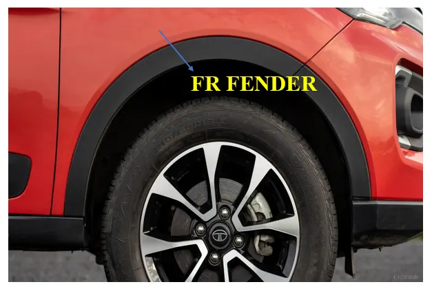
Fig_1: Front fender
Most of the passenger vehicles have four fenders, one over on each wheel and in some automobile have more than four fenders like bus, trucks, and etc.
PURPOSE OF FENDERS:
- Fenders primary purpose is to prevents inside of the car body from the sand, mud, rocks, liquids and other substances being thrown into the air by the moving vehicles tyre.
- It also protects from injuries to the pedestrians and contain the motion of these particles.
TYPES OF FENDER:
Based on the profile it has to be classified in to two types of fender and these are the following as,
- Full bumper type Fender
- Half bumper type Fender
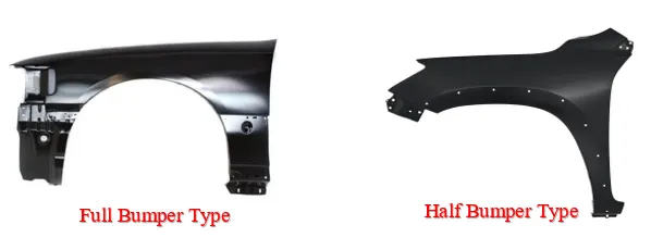
Fig_2: Types of Fender
DESIGN CONSIDERATIONS & REGULATIONS:
- Drip area
- Wheel arch and its regulations
- Mountings
1_DRIP AREA
- Keep 3o of draft angle and gaps from fender RR 200 to 300 mm for cowl top and fender FR 150 mm for Head lamp and remains considered drip area.
- Drip area depth shall be uniform like A=B=C. And also ensure that the depth of itself must be keep 40 mm or less. Because more than that can’t able to produces the part where as more drawing depth may result in spring back effect.
- Minimum requirement of the drip land area keeps 37 mm for creating embosses itself and also consider the end most of the drip area to the engine comportment must be keep 10 mm of gap.
- Contact bracket in the engine compartment and the mounting area of drip surfaces keep remains flat.
2_WHEEL ARCH & ITS REGULATIONS
Wheel Arch in Fender Design consideration it plays major role to keeps wheel or tyre inside of the wheel housing and it also provides to keep all possible motions of the wheel in a vehicle. It can be defined as the semi-circular shaped part that has to be positioned above the wheel of a vehicle.
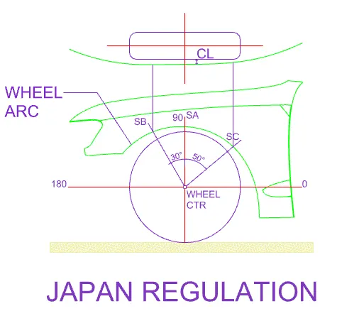
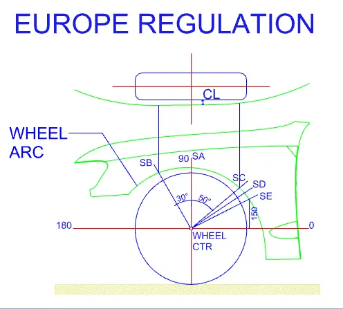
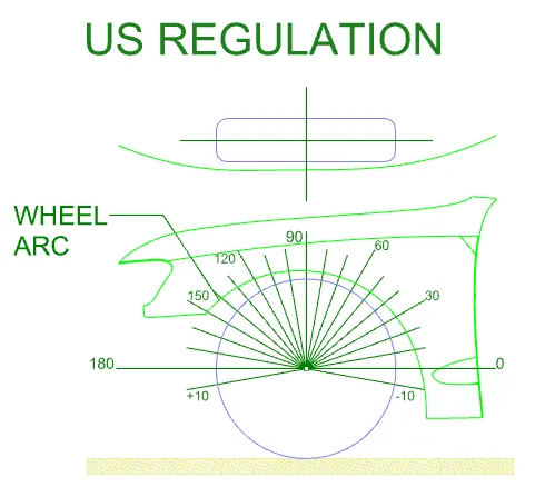
Wheel arch it can be varying for region to region and it have specified regulations itself while calculating the wheel arch. And the various types of wheel arch regulations are listed below,
- Japan Regulation
- European Regulation and
- US Regulation
Regulations:
 |
 |
 |
|
3 Control points |
5 Control points |
21 Control points |
|
From wheel centre axis 30o forward to 50o backward |
From wheel centre axis 30o forward to 50o backward also intersecting from 0o line of 150 mm and its inter-mid |
From wheel centre axis backward 100o to forward 100o of every 10o. |
|
Required CL more than 5mm |
Required CL more than 10 mm |
Required CL more than 10 mm |
Table_1: Fender Design Wheel arch Regulations
3_MOUNTINGS:
In fender design mounting of fender is also be the important criteria and it has to be mounted by using the fasteners itself. And following these are the mounting regions of a Fender,
- Body
- A pillar
- Sill
- Baffle and Bumper
- Drip
OBJECTIVE:
To design a FR Fender from the given skin data and given master section with drip area mounting, A-pillar, Sill, Bumper and Baffle mountings.
GIVEN DATA:
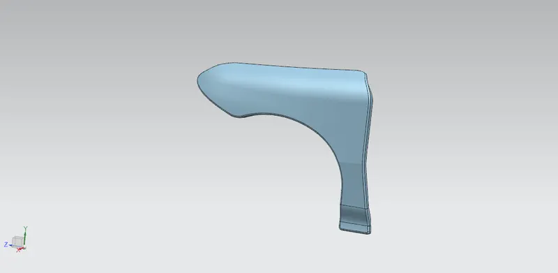
Fig_3: Fender Given Skin data
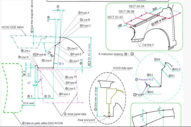
Fig_4: Fender _Given Master sections
TOOL USED: NX_12
DRIP MOUNTING:
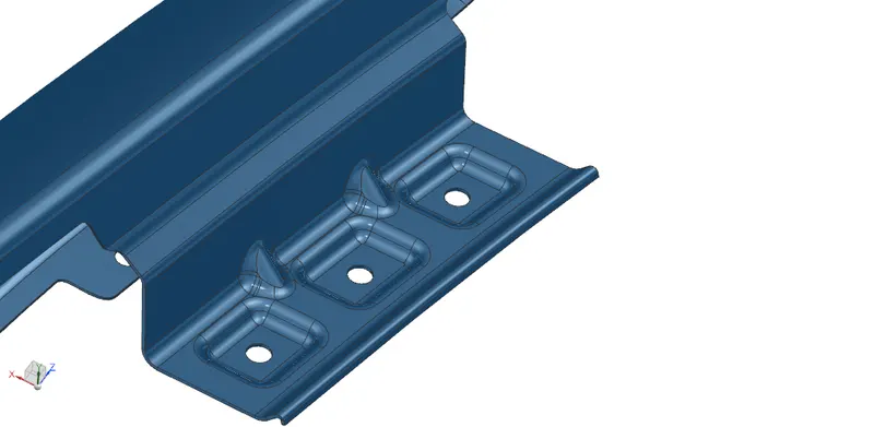
Fig_5: Fender Drip mounting
A-PILLAR MOUNTING:
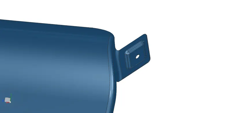
Fig_6: Fender A-pillar mounting
SILL MOUNTING:
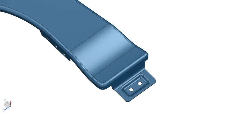
Fig_7: Fender Sill mounting
BUMPER MOUNTING:
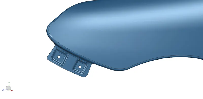
Fig_8: Fender Bumper mounting
BAFFLE MOUNTING:
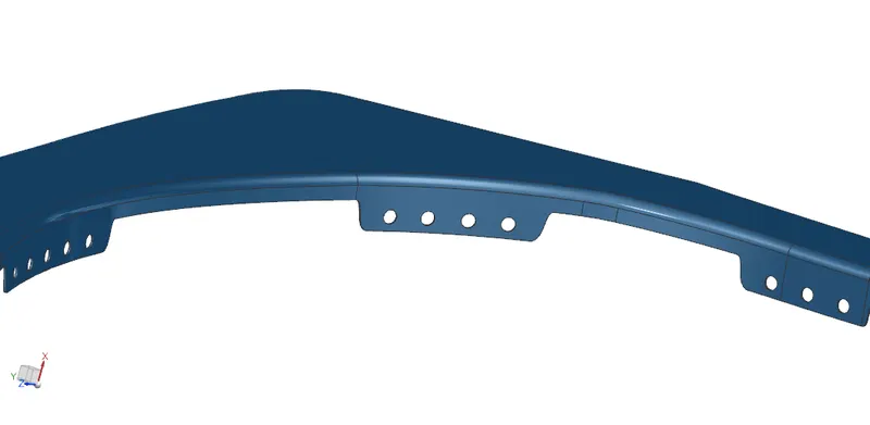
Fig_9: Fender Baffle mounting
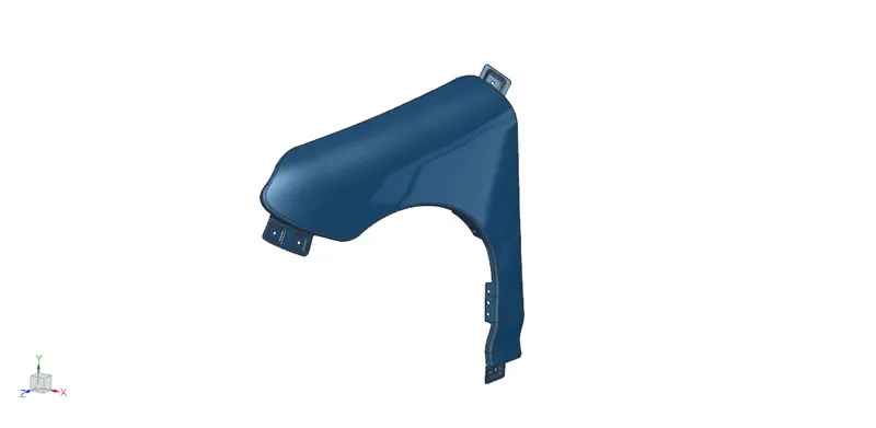
Fig_10: Fender Render
CONCLUSION:
Hence the given skin data and master section of a Fender thus design has to be done and its all the mountings are done by keep following above all the design considerations done by using NX_12 tool.