Fender Design
FENDER DESIGN
AIM
To design and develop a fender with reference to the master section and class A surface given by following all the design guidelines of a fender with all manufacturing and assembly constraints.
Introduction
The fender is the curved part of the car’s body that sits on top of the wheels and holds them in place. It is not only a safety component but also enhances the overall look of your vehicle. Its primary function is to shield and protect the passenger compartments by preventing sand, mud, rocks, liquids, and other roads spray from being thrown into the air by the rotating tire. A fender is merely a housing for the wheels that prevents road debris from being thrown up by the rotating tires and protect the pedestrians on the road and fender are also able to absorb impact from minor collisions.
There are two types of fender
1) Full Bumper type-Traditional type bumper as name suggests it comes in a single part combination of bumper and the fender, which is very difficult to handle and manufacture.
2)Half bumper type-Half bumper is developed for the easiness of manufacturing, assembly and service and there-by reducing the manufacturing cost by maintain all safety constraints.
Manufacturing process of fender
The fender injection molding process includes four important stages: filling, packing, cooling, and ejection. A primary traditionally concern in injection molding has been that of the extent to which high-quality products with strong mechanical properties can be manufactured, in the absence of any undesired defects. Optimization of injection molding process for car fender in consideration of energy efficiency and product quality.
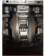
fender injection moulding process
Input received
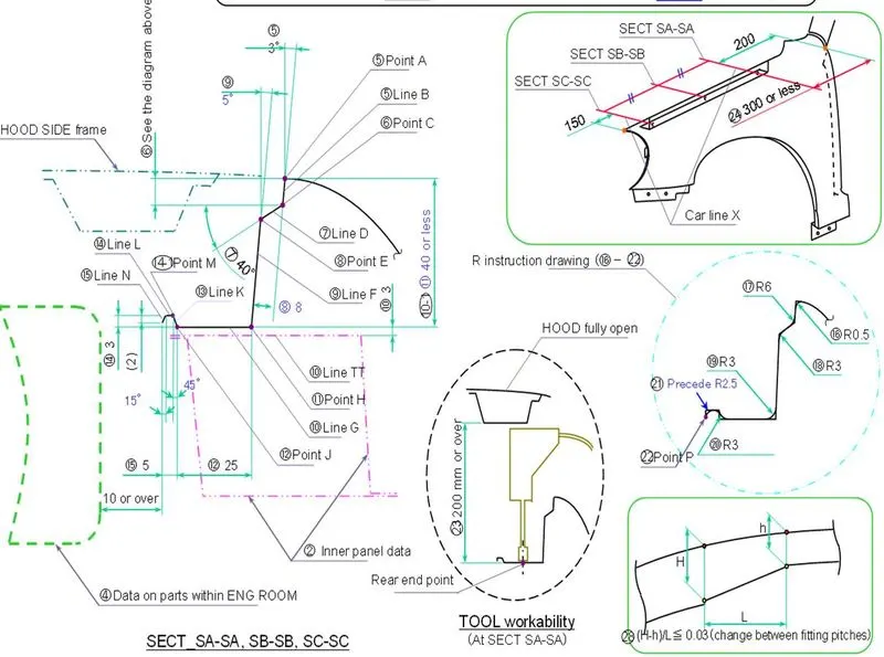
Master section
Class A surface
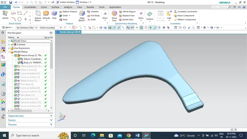
As the master section and class A suggests here we are going to design half bumper fender which is widely used by all the manufacturer’s.
Guidelines to be followed while designing a fender
- Minimum clearance between engine compartment and final emboss of drip area-10mm
- Edge blend -Minimum 3 degree + thickness of the material for all edges
- Maintain a height of less than 60mm (40mm preferable) for flat surface in mounts to avoid the spring back effect.
- Contact bracket between hood and fender-40mm
- Clearance from front end- 150mm clearance from the headlamp housing to the drip mount area.
- Clearance from rear end-200mm or max 300 clearance from cowl drip area.
- Minimum 7 degree draft for all emboss and law extension area.
- All the dimensions should be maintained as per the master section
Mainly there are five mounting points to be considered while designing a fender,
1) Drip area
The hood and fender are joining together by this mount using mechanical fasteners, which can be see one we open the hood.
As the master section clearly explains all the dimensions and design features we can follow the master section to get the fender with all design parameters.
Gap from front end- 150mm clearance for headlamp housing.
Gap from rear end-200mm or max 300 clearance for cowl drip area.
Developing the model using NX
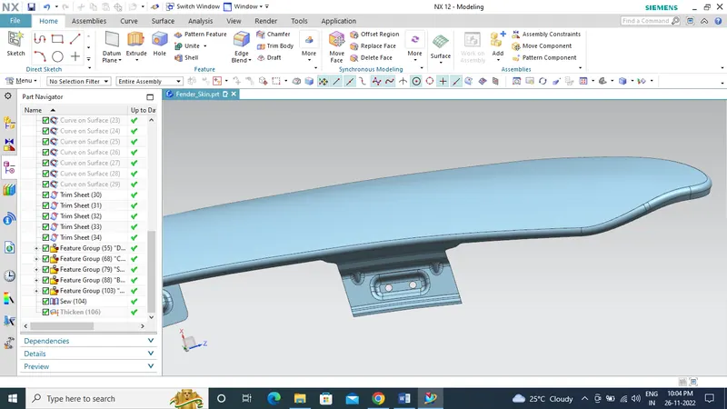
Drip mount area with emboss and provision cutout for fasteners
2) Cowl Panel / A pillar
A pillars are located on either side of the vehicle front window (or windshield). The wiper and its accessories are mounted here these are used as a cover that fills the gap between the hood and windshield of the car. It also supports the dashboard and ensures that no unwanted parts get into the windshield wiper system or the cabin filter area.
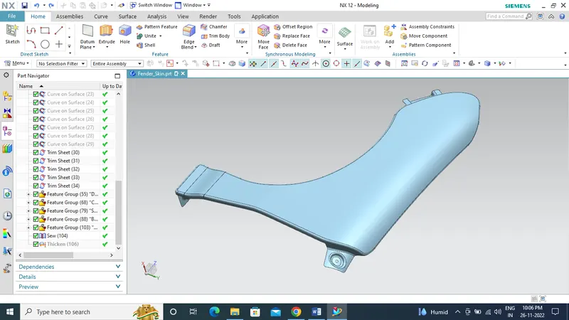
Cowl / A Pillar mount area with emboss and provision cutout for fasteners
3) Sill
A vehicle body comprises a sill along a lateral end of a floor panel forming a lower side of a door opening. The sill is an open section, one piece member having an opening extending throughout the length thereof. A cover of a plastic material is removably attached to the sill in a manner to define a closed sill configuration.
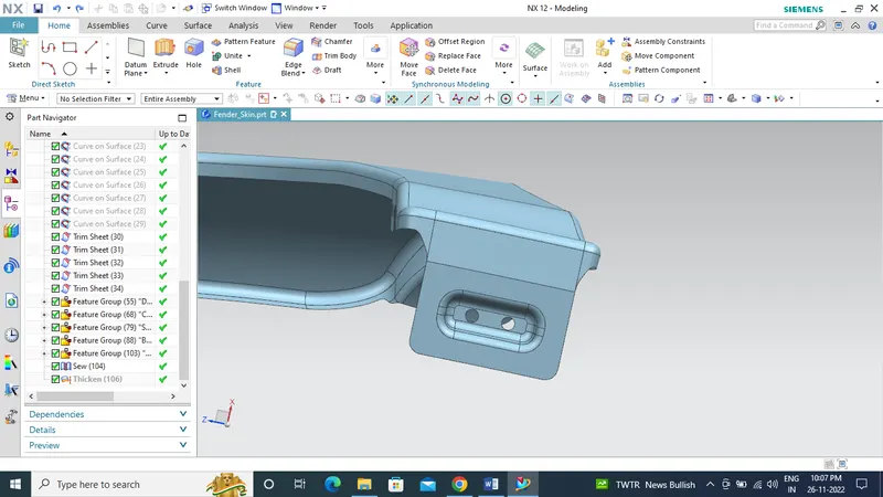
Sill mount area with emboss and provision cutout for fasteners
4) Baffle
‘Baffle’ or ‘Mudguard’ means a rigid or semi-rigid component intended to trap the water thrown up by tyres in motion and to direct it towards the ground. Mudguards may entirely or partially form an integral part of the vehicle bodywork or other parts of the vehicle such as the lower part of the load platform, etc.
It will also reduce the risk of small objects, in particular pebbles, being picked up from the ground by the tyres and thrown upwards or side wards towards other pedestrian.
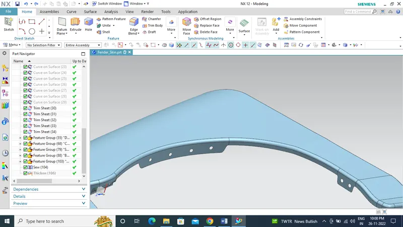
Baffle mount area with provision cutout for push pin /clips
5) Bumper mounting area
A bumper is located on the front and rear of a vehicle. The purpose of a bumper is to absorb the impact of minor collisions. mechanical fasteners are used to joining this mount.
The baffle is mounted to fender by using push pin / clips.
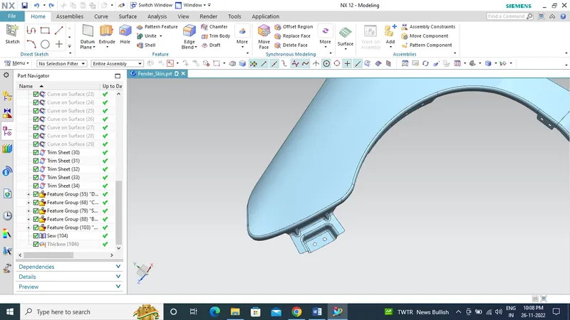
Bumper mounting area with emboss and provision cutout for fasteners
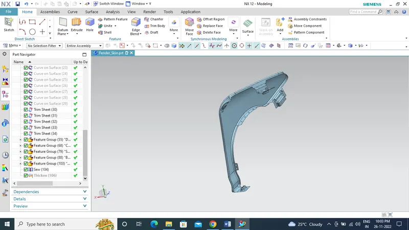
Final design of fender with all the mounting area
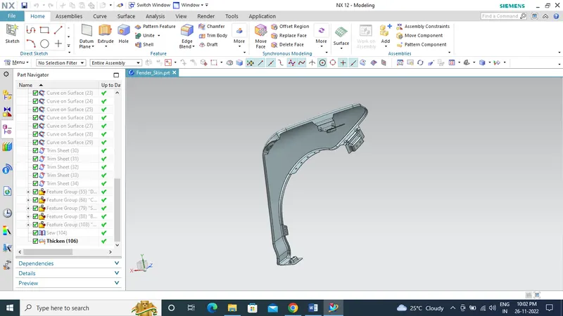
Solid body 0.75mm thk of Fender with all the five mounting area
Conclusion
Thus the fender has been successfully designed with all mounting points by following the master section and the design guidelines.