Fender Design
Fender:
Fender is the term for the part of an vehicle body that frames a wheel well (the fender underside). Its primary purpose is to prevent sand, mud, rocks, liquids, and other road spray from being thrown into the air by the rotating tire. Fenders are typically rigid and can be damaged by contact with the road surface.Sticky materials, such as mud, may adhere to the smooth outer tire surface, while smooth loose objects, such as stones, can become temporarily embedded in the tread grooves as the tire rolls over the ground. These materials can be ejected from the surface of the tire at high velocity as the tire imparts kinetic energy to the attached objects. For a vehicle moving forward, the top of the tire is rotating upward and forward, and can throw objects into the air at other vehicles or pedestrians in front of the vehicle.
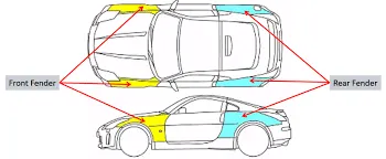
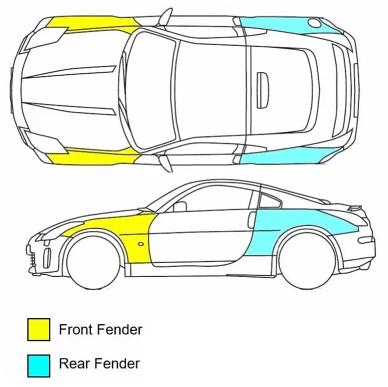
Its primary purpose is to prevent sand, mud, rocks, liquids, and other road spray from being thrown into the air by the rotating tire.
When vehicle is moving, tires pick up stones and others and hurl them in all directions. Fenders are basically present to prevent any injuries to pedestrians and contain the motion of these particles.
About of Front Fender:
A car fender is a rigid vehicle panel that houses the wheel well. It forms an arch that is designed. Fender made either of plastic or metal on the side of the vehicle body, around each of the wheel cut-outs. Rotating tires can throw lots of water, snow, or pieces of debris while driving, so fenders help mitigate some of this matter. Fenders can take a beating from the environment and daily driving conditions. They provide protection against outside conditions plus rocks and other types of debris thrown by wheels.

02.Types of Front Fender:
Full Front Fender:
The fender's openings for the wheel wells tend to be much larger than the diameter of the tire because they do not move with the tire suspension and consequently must be large enough to allow the full range of tire motion on the suspension without touching the interior of the wheel well.
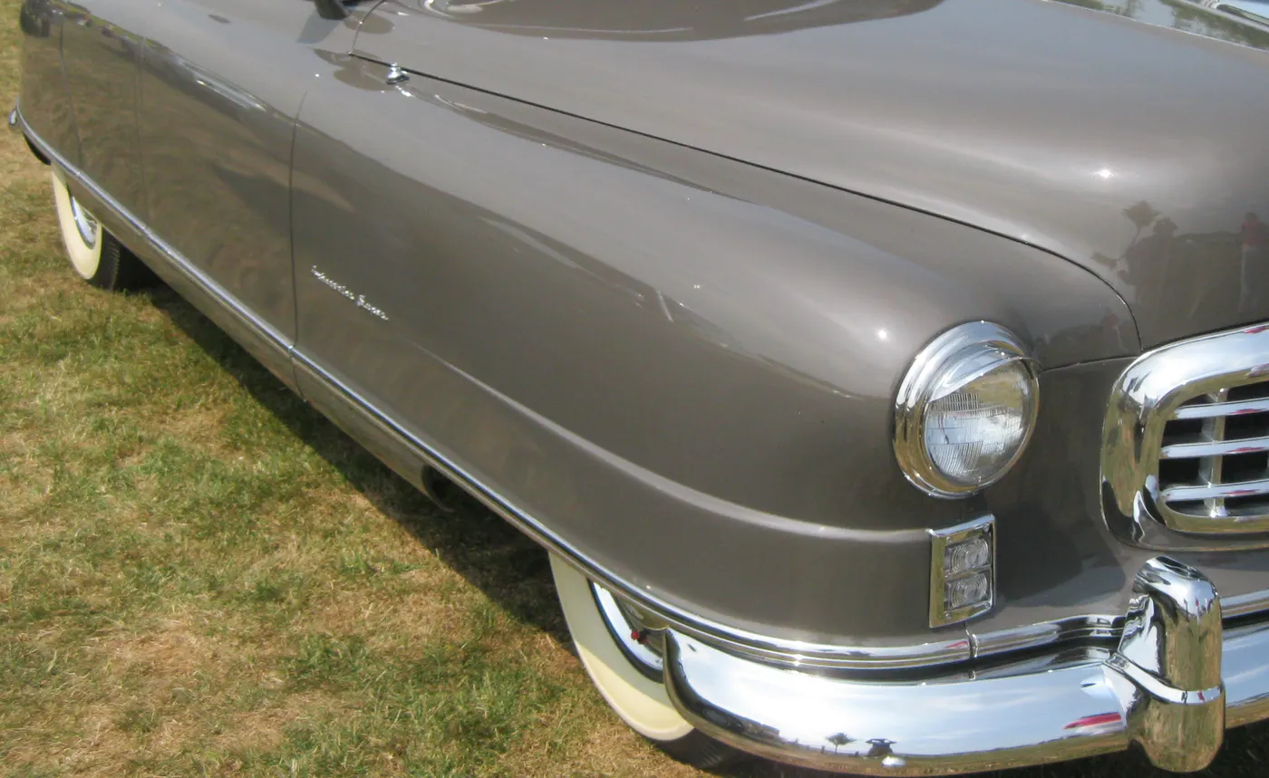
Half Front Fender
The fender is on the side of the car, over the wheel. The bumper is installed on the front and rear sides of the car. Its main function is to the half fender minimize steel weight and improve the mileage of the cars.
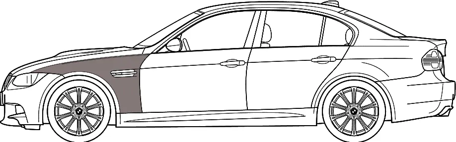
There are two types of fenders used in cars. They are,
- Full bumper type and
- Half bumper type.
- Full bumper type:
In full bumper type, the fender covers the entire wheel area from the front to the body side. This type is widely used by the OEMs and automotive industries in early days.
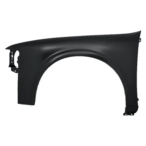
Full bumper type front fender.
- Half bumper type:
In half bumper type, the fender only covers the one-third area of the wheel from the bodyside to front. This is because to reduce the production cost and material wastage compared to the full bumper type. This type is widely used by the OEMs and automotive industries now-a-days.
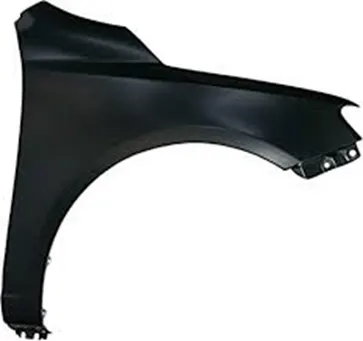
Half bumper type front fender.
In this project, the half bumper type fender is the commodity which is given by the styling team to design and develop from the styling surface. Every fender design has its own and specific mounting areas in the required positions for assembling it with other parts of the vehicle. Those mounting areas are simply said to be the fender mounts.
Purpose of Fender Design.
The primary purpose is to protect the wheel and prevent road debris such as rocks, sand, and mud from being thrown into the air by the spinning tire and absorb the impact upon collision, minimizing the damage to the main body. A pair of front and rear fenders can be found on each side of a vehicle. Fender also improves the Luxurious car look and safety Purpose in the engine compartments elements.
Fender mounts:
As we seen earlier, the mounting areas in a fender is said to be the fender mounts. These fender mounts are classified according to its position like,
- Bumper mount
- Drip
- A-pillar mount
- Sill mount and
- Baffle mounts.
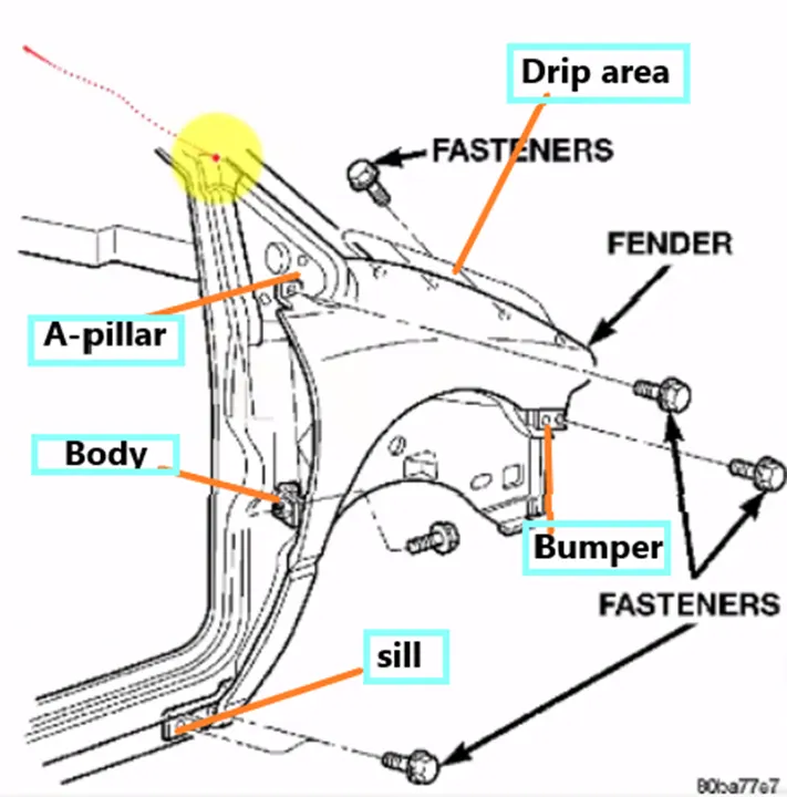
Fender mounts and its associated areas are shown.
Design parameters:
There are certain standards are followed by the OEMs for designing the automotive commodities, these standards are framed from the trail and error method which is carried out by the OEMs and automotive industries to meet the safety requirements, reduce the production cost, material wastage and increase the efficiency of the components.
As we seen before, a fender consists of 5 major mounts. These mounts are designed with respect to its standards and given parameters.
Some common parameters for a fender design are, the blends should be minimum of 2.5mm radius to avoid the sharp edges, then there must be clearance of about 3mm - 5mm between the blends and the fastener holes.
For drip area, master section is given to design the drip mount following the parameters mentioned in it.
Master section:
Master sections are the 2D outlines which is taken at a particular area of a 3D model or it is an intersection of 3D model about a reference plane to study its outline (or boundary) in a 2D view. These master sections are widely used in OEMs and in automotive industries to convey the functional requirements of commodity to the design engineer.
It gives the parameters like length, width, height, radius and clearance should be considered while designing the particular part or component.
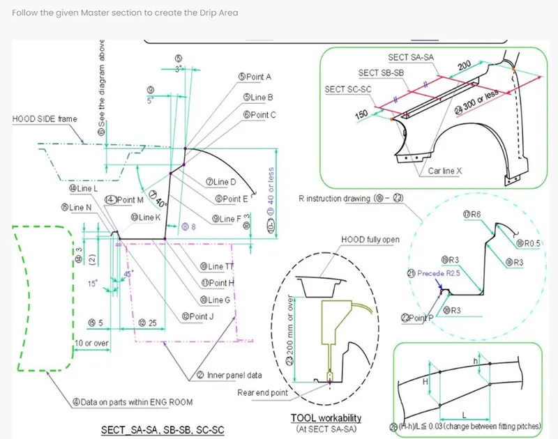
Drip area master section is shown.
For this project, the given master section gives the parameters to be considered while designing the fender drip mount.
- The drip mount should have atleast or minimum 150mm of clearance at the front side of fender for headlight housing.
- And at the back side of fender, there should be minimum of 200 mm and maximum of 300mm clearance for the cowl (wiper mounting part).
- Then the hood side drip depth must be 40mm or less as maximum productivity is achieved at the depth of 40mm. If depth exceeds 40mm, rigidity bead is to be provided. Also, forming is not feasible if depth exceeds 60mm due to wrinkling and spring back.
- The initial extension of drip flange must be minimum of 3º draft and then a 8mm extension with 40º draft with respect to the previous flange should be maintained with another extension having 5º draft to improve the aesthetics of parting gap between hood and front fender. And all these drafts must be in positive tooling direction.
- Then the extension for fasteners from flange must not exceed 25mm to maintain the clearance of 10mm or more between the engine room and fender drip.
We have to check the styling parameters also, before designing the fender to avoid error at early stage. Those parameters are,
- A parting shall be provided within a range of 47.5mm from SRL (reference line on the hood side: a line in which the fender makes contact with the surface inclined by 45º with respect to GL), if there is no problem in terms of styling.
- The height shall be 80mm min (child, and WAD1700 Max).
- The height in the range of WAD 1700 min shall be 94mm (+14mm that corresponds to the amount of increase in inertial energy) to meet the adult impact requirements.
Design procedure:
First an offset of 0mm of the styling surface is created, this offset is going to be the working surface.
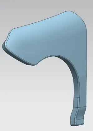
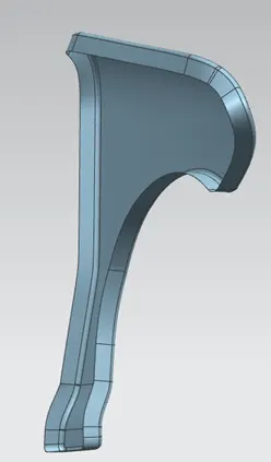
Working surface of fender is shown.
- Drip mount:
It is a mount in front fender, which is used to assemble it with the engine compartment of a vehicle.
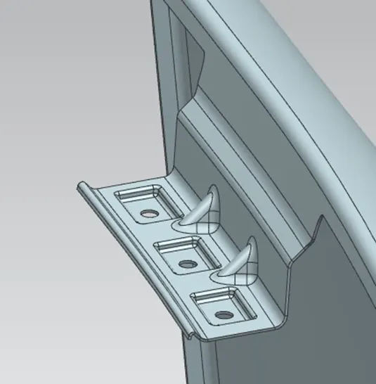
Drip mount is shown.
- The given styling surface already have the initial flange for the mountings.
- In the working surface by using “offset curve in surface or face” command, the lower curve of the blend is offset to 5mm.
- Then using “curve on surface” command, necessary curves were created on this flange with respect to the offset curve to remove the unwanted regions of the flange.
- For the drip area, two planes were created at the front and back of the fender with respect to the master section.
- After creating the planes, intersection curves are created about these planes on the fender surface.
- Then the law extensions are carried out to create the drip mount according to the master section.
- And the sharp edges of the extensions were blended with the face blend command and again the dimensions are taken from the master section.
- Before applying face blends, the darts are created using the dart command to give some support to the flange.
- After creating the drip flange, a plane is created with respect to its flat surface to create the sketch which is going to contain the clearance for fasteners.
- With help of this 2D sketch, the required embosses were created on the drip flange with respect to the plane created before to obtain flat surface for ease of mounting.
- Finally, the clearance for fasteners were created using the sketch in the embosses.
- Bumper mount:
It is a mount in the front fender, which is used to assemble it with the bumper part.
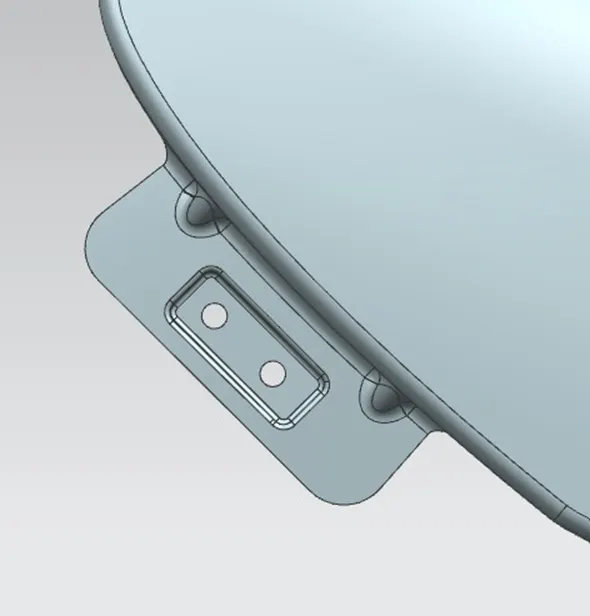
Bumper mount is shown.
- The unwanted region in the flange is trimmed off with the help of curves which are created before using the “curve on surface” command.
- Then law extension command is applied to create the required extension which is normal to the fender flange surface and its sharp corners were trimmed with help of bridge curves.
- A new plane is created with respect to the extension created before. On this plane 2D sketch is created and projected to the bumper mount extension.
- With help of this projected curves, embosses and fastener clearance holes were created.
- The support darts also created in a certain gap, to provide extra strength to the mount.
- Finally, the blends were created at the sharp edges and corners.
- Baffle mount:
It is a mount in the front fender, which is used to assemble it with the baffle or splash part.
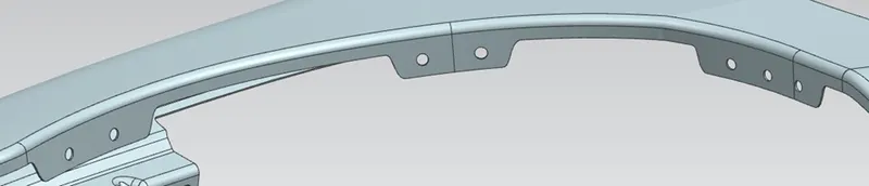
Baffle mounts are shown.
- The unwanted region in the flange is trimmed off with the help of curves which are created before using the “curve on surface” command and its edge is extended to a certain distance.
- A new plane is created with respect to the extension created before. On this plane 2D sketch is created and projected to the bumper mount extension.
- With help of this projected curves, the clearance holes for the baffle push-pins were created by trimming the flange surface.
- The same procedure is followed for next to flanges also.
- Finally, the blends were created at the sharp edges and corners.
- Sill mount:
It is a mount in the front fender, which is used to assemble it with the sill (sill is the lowermost part associated at the sides of vehicle BIW).
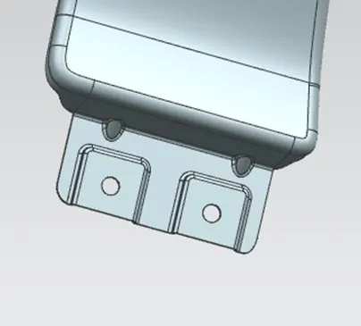
Sill mount is shown.
- The unwanted region in the flange is trimmed off with the help of curves which are created before using the “curve on surface” command.
- Then law extension command is applied to create the required extension which is normal to the fender flange surface and its sharp corners were trimmed with help of bridge curves.
- A new plane is created with respect to the extension created before. On this plane 2D sketch is created and projected to the bumper mount extension.
- With help of this projected curves, embosses and fastener clearance holes were created.
- The support darts also created in a certain gap, to provide extra strength to the mount.
- Finally, the blends were created at the sharp edges and corners.
- A-pillar mount:
It is a mount in the front fender, which is used to assemble it with the A-pillar of a vehicle BIW.
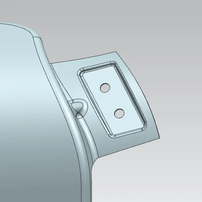
A-pillar mount is shown.
- The unwanted region in the flange is trimmed off with the help of curves which are created before using the “curve on surface” command.
- Then law extension command is applied to create the required extension which is normal to the fender flange surface and its sharp corners were trimmed with help of bridge curves.
- A new plane is created with respect to the extension created before. On this plane 2D sketch is created and projected to the bumper mount extension.
- With help of this projected curves, embosses and fastener clearance holes were created.
- The support darts also created in a certain gap, to provide extra strength to the mount.
- Finally, the blends were created at the sharp edges and corners.
After creating the mounts, whole fender surface is thickened using the thicken command to create a solid part with 0.75mm of thickness.
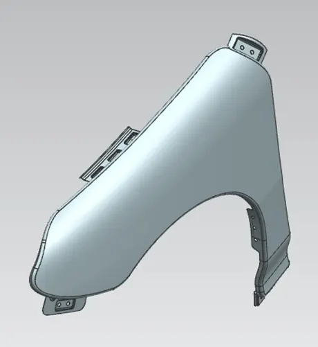
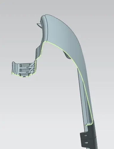
Thickened fender part is shown.
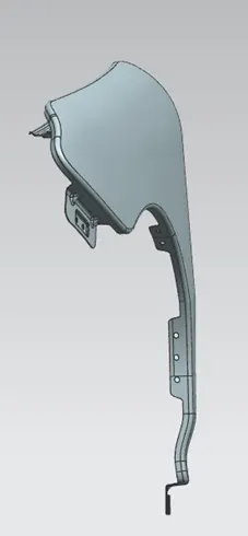
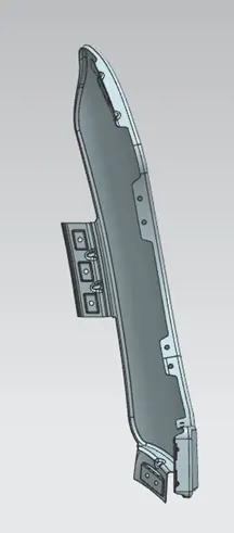
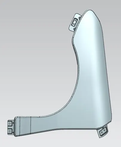
Top view, front view and side view of the fender is shown.
Manufacturing process:
The manufacturing process includes the following steps that firstly, unfolding and shearing are carried out on a plate, wherein a proper cold roll specification is selected at first, a cold roll is unfolded, and then the unfolded cold roll is sheared to an iron plate of the corresponding size according to production material specifications; secondly, oil pressing and punching are carried out, wherein the iron plate is extended at first, then side shearing and punching are conducted on the iron plate, folding and shaping are carried out on the iron plate, and finally reshaping is carried out on the iron plate; thirdly, small first parts of the fender are machined, wherein first of all, the iron plate is punched to a needed outer contour blank, then the iron plate completing the outer contour blank is further shaped, and the iron plate is punched at last.

Stamping (also known as “pressing”) is the process of placing flat sheet metal in either blank or coil form into a stamping press where a tool and die surface forms the metal into a net shape. Stamping includes a variety of sheet-metal forming manufacturing processes, such as punching using a machine press or stamping press, blanking, embossing, bending, flanging, and coining. This could be a single stage operation where every stroke of the press produces the desired form on the sheet metal part, or could occur through a series of stages.
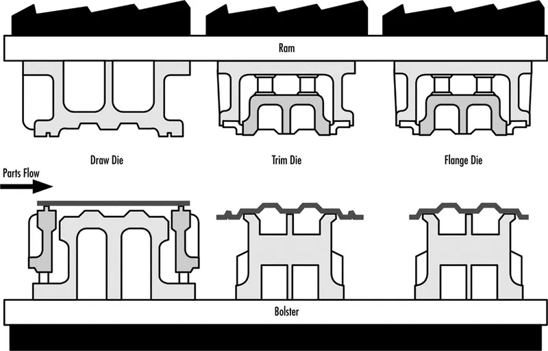
Stamping sequence is shown.
CONCLUSION :
Thus, all moounting areas for the car front fender which is designed from given skin data and also consider the master section is done by following all design rules.