Fender Design
Aim:
To design a front fender of a car with its standard regulation and design requirements from provided master section and skin data.
Introduction: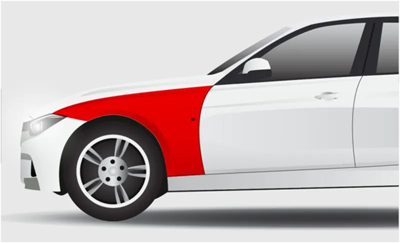
Fig - Fender in a car
Fender is the US English term for the part of an automobile (vehicle body) that frames a wheel well (the fender underside).
Its Primary purpose is to prevent sand, mud, rocks, liquids, and other road spray from being thrown into the air by the rotating tire.
When vehicle is moving, tires pick up stones and others and hurl them in all directions. Fenders are basically present to prevent any injuries to pedestrians and contain the motion of these particles.
Body side has a integrated fender, where as front fender is a separate closure component As we know front fender is one of the side closing component for the engine compartment and the major role for a front fender is to avoid chipping inside the engine compartment.
During motion the wheels try to pick up some sand and mu particles and small stone particles and throw it inside the car and this fender wil be helpful in preventing them hitting inside the body, inside the engine compartment basically. And this fender will have a plastic part and this plastic part is lying on this area and this is the bigger part which will be protecting your engine compartment basically and this fender also plays a major role to prevent injuries for the pedestrians . whatever commodity we design we will have to think of the pedestrians who is being attacked to this. For example, anti chipping is also one of the pedestrian safety criteria because these stones which gets chipped from the tyre may tent to hit the pedestrians also so we would recommend to have strong fender so that our pedestrians are also safe parallel this also covers the engine compartment so that we don’t see don’t see a inner region from outside.
Functional Requirements of Fender:
Most passenger automobiles have four fenders, one over each wheel. For vehicles with a narrow car body that exposes the tire, the fender is an exposed curve over the top of the tire. For wide body vehicles that cover the tire, the fender forms the wheel well surrounding the tire, and is not directly visible from above the car body.
Wheel wells tend to be much larger that the diameter of the tire, because they do not move with tire suspension and consequently must be large enough to allow the full range of tire motion on the suspension without touching the interior of the wheel well.
More elaborate designs include fender skirts for enclosing the outside edge of the wheel well, and stylized pontoon fenders for exposed fenders.
When getting into the design we have two types of fender:
- Full bumper type
- Half bumper type.
- Full Bumper Type: Full fender type is traditional type of fender where more material consumption is observed. This type is used in old design of automobiles where it increases the overall weight and thus reduces performance. The maintenance also relatively more due to more surface.
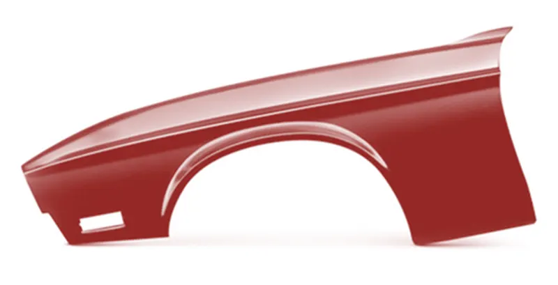
Fig. Full Bumper type fender - Half Bumper Type: Half fender type is modern design where less material consumption is observed, so productivity increases by reducing size of blank and thus providing more performance. The maintenance also relatively low compared to full bumper type.
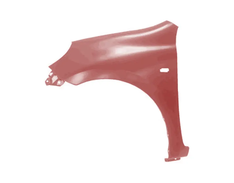
Fig - Half Bumper Type
Presently the conventional methodology are, the basic type what we are using is half bumper type. What is the major reason of going for the half bumper type. Whenever we use a full bumper type the blank what we used to create this full bumper type is really big and we have quite a lot of wastage around, but in the case of half bumper type we have a high possibility to reduce the scrap which means by slightly increasing the blank size we can produce fenders at the same time. This is what is called as scrap management.
So when we have been given with the styling we will be choosing half bumper type because we are reducing the material usage. And that is why people started using half bumper type because every inch of a steel or a sheet metal is a cost. This will reduce the blank cost drastically so that we provide customers a better fender for a cheaper price. This methodology will allow us to use a lot of plastics on the bumper which means you are reducing some particular proportion of steels weight. When we particularly reduce the proportion of steels weight, we also increase the performance of the vehicle. This is also one of favorable decision what we make to reduce the weight. That is why we started using the half bumper type.
Mounting:
There are 5 mounting points in a fender
They are:
- Body
- A Pillar
- Sill
- Cowl
- Drip
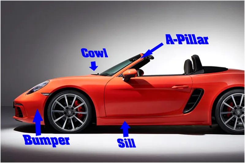
Fig - Regions connected with fender
Cowl is the plastic part, where your wiper mounting is installed.
Drip area is a region, where the fenders get contact with the engine compartment.
We use fasteners, because the fasteners regions are anyways closed. ORVM, Bumper, spoilers/sill outer that will hide the fasteners, so there is no worry for us to use fasteners here and this is not going to have any impact aesthetically. And since this also is a styling oriented part we don’t give this to suppliers mostly. We develop this part within the house (i.e. within our production unit).
Fender Drip Area:
Major and important very mounting is the drip and this is the connection of the fender with the engine compartment these are all images of fender drip areas of different cars which is used to mount on the engine compartment. As we see the pictures we can identify that design consideration is same throughout all the cars. The material is prepared in such a way that we have a standard design consideration which could be used by any OEMs. The basic consideration what we express, or the basic design consideration what we express will really be similar between all OEMs and this is fastening technique what is used to join the materials on all 5 mounting regions.
Study of fender drip area:
Drip area, as we know that this is the joining between the fender to the engine compartment, and this has a lot of design constraints to be followed. The first major thing what we got to understand is the gap from the rear end of the fender and the front end of the fender. WE have seen about cowl top part, that cowl top part will carry the wiper motor and its instruments. To have some sufficient mounting space for this cowl top, we minimum need 200mm. so when we start preparing our fender drip area, we will take this 200 mm and then we start our drip. Similarly we all know there is going to be a head lamp here. This headlamp will have an housing unit. At this housing unit, to have sufficiently placed we need atleast150 mm distance . and this length is defined with respect to the length of the fender. So we don’t have any pre-defined length on this region, but the front clearance and the rear clearance is really important. When the cowl top becomes smaller than the conventional cowl top, we can reduce the 200mm size, but on the most of the cases we have 200mm gap and 150 mm gap. So the remaining area will be our fender drip area. And to develop this fender drip area, we need a master section.
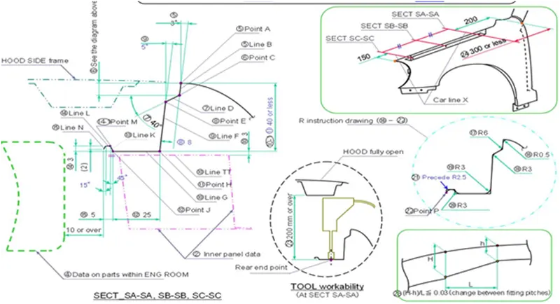
Fig. Master Section for fender drip area
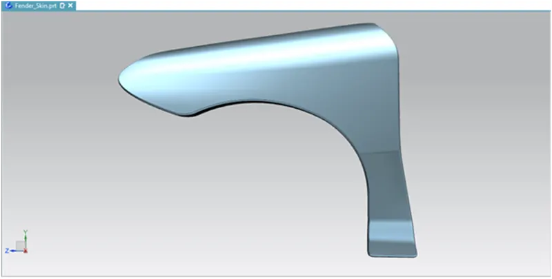
Fig. Fender Skin DataThis is the master section, this will be the point what we get from the styling team and this is the fender surface what we have from the styling. After that we go 9 mm as deep as inside and we open the angle by 3deg. Why do we do this for 3 deg and why not for any other reasons we have the solution here. this 3 deg opening is given for drawing reasons. If it is less than 3 deg, If it is straight it will be difficult for production purpose. We will have to open a little. When we open this our minimum opening angle what we have to follow is 3 deg, that is how the tool will work so we give the 3 deg. How deep should we go and why it is basically 9 mm is, it is the minimum most requirement what you have to follow, when we do this, we will again have a gap and prepare an opening of 3 deg. The reason for this purpose is when you see the hood outer and the fender from the outside we will find a small gap. This gap should be the one which is preventing the visibility inside. Our design intention should be we should not see anything which looks not good inside the engine compartment. Logic is when a human protrudes inside the surface we would have create will stopped the image and you don’t see anything which is not good inside the fender drip area. Because, the fender drip area is mounted via weld nuts to the engine compartment. So it will not be good to see the fasteners from the outside, when we prepare a flange here at this dimension, we don’t allow the consumers to see the fasteners or any other not good looking area inside the engine compartment. And so that is why we create a dimension between the 7 to 8 mm. when we do this we prevent the visibility and the fender drip area distance we will have minimum of some value between35 to 40. This 35 to 40mm reason is for the tool to come and work perfectly inside. We will open the hood and mount our fender and then fix it with the help of weld nuts. So which means, the assembly sequence is we have car body without the hood and first we will mount our hood on the hinges, and we keep the hood in open condition and then we mount the fender with the help of the tool and to axes this tool we need at least 200 mm gap. When we have hood in open condition we definitely have 200 mm condition. this is just a reference for us. And the landing area is also the minimum most required surface to meet inside the engine compartment. So this is how we prepare the drip area and this is given to add strength, an empty surface is more witherable, when we give an emboss or structure there we strengthen the part but we should make sure that there is no other part inside the engine room at least for 10 mm. if we have this passed, we can exceed the drip area. So our basic requirement is the end most part which will be in contact with the fender drip area should have at least 10mm clearance so that we don’t hit or damage while assembling the part. while assembling the commodity inside the engine room. And then with respect to this, we vary the values in fender drip area.
Hood side drip depth must be 40mm because the tool which is producing our part will have the tendency to punch this deep and if it goes more than this, it will be difficult for punching it. We have a big material and we are going to punch and it cannot go more than 40 mm most of the times(majority of the times). There are some tools which are capable of doing only till 30 mm, yes we can also do that, the more deeper , the more difficult the part is, so this is a kind of optimum value where most of the cases is achieved, if it exceeds more than 60 mm we tend to get a spring back effect. We have to assure that the part should not produce any spring back effect. Out of parent car and experience we have we detect this value.
Design Criteria:
- Embosses are provided to increase the strength.
- Smooth curves are designed for easy manufacturing of panel.
- Ribs are provided to drip area mount to give structural support and extra strength.
- Maintain extra 10 mm from the flat surface for the fastner holes.
- All fillets should maintain 3 + thickness mm radius in most regions.
- Thickness of fender is 0.75 mm.
- A Pillar Mounting
Here this region is mounted to the A-pillar frame of the chasis so that it is rigidly attached to the body of the car. A car has many pillars according to the design and the style of it. It is the number of vertical portions in a car. In a sedan type of car, there will be three pillars. If it is a hatchback model, then it has four pillars. The front most pillar is called as A- pillar. This mounting is assembled with A-pillar of the car.
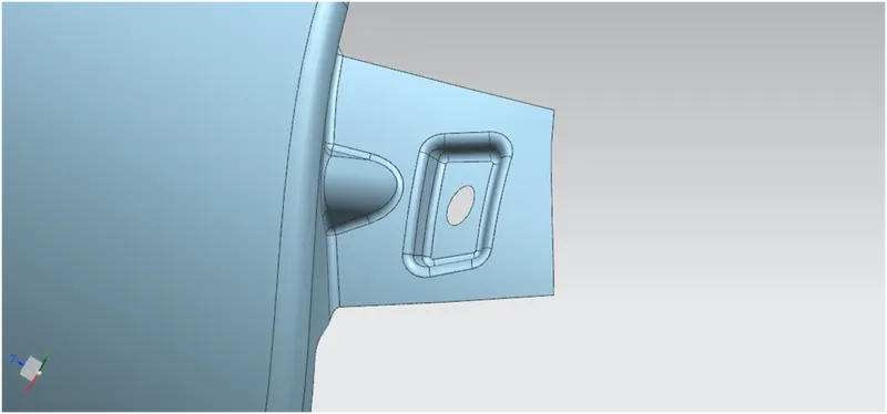
Fig - A-Pillar MountingPROCEDURE
- First the skin data provided by the styling team needs to be extracted.
- outer edge of the fender was offset inwards to particular length.
- Using the curve on surface command the unwanted portion were trimmed out using trim sheet.
- By using the law extension, the A-pillar were extended and trimmed on the sides to get a flat edge.
- For creating a flat emboss which was used to mount the fender with the A-pillar a datum plane was created.
- Then the required sketch was drawn on the datum plane and projected to the surface.
- To create a fastener hole which needs to be around 5 mm gap around it trim surface command were used.
- Atlast the required blends were added using face blend and edge blend.
- Drip Area mounting
This region is mounted below the hood inner panel which needs to be in flush when the hood is in closed condition and also there should be very less gaps. The drip area is either spot welded or in some cases bolted down via self-tapping screws.
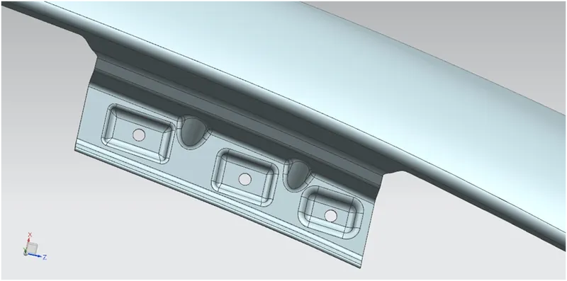
Fig - Drip Area MountingPROCEDURE
- By using the information in the master section provided the drip mounting were created.
- The drip area must be minimum 150 mm apart from the front edge so that the drip mounting won’t disturb the head lamp mountings.
- From backwards the drip area must be 200 mm apart from back edge to avoid the coincidence with the engine cables.
- The flange for the drip area mounting is extracted as Considering the front and back clearance.
- The emboss and dart is provided to strengthen the mounting area and to avoid the NVH.
- Then for creating the fastener holes the trim sheet options were used.
- Then the required blends were created for improving the aesthetic of the fender.
3. Bumper Mounting : This region is designed to mount the bumper here. It plays an important role in holding the bumper at its own place. If it got damaged the bumper won't get any support from anywhere.
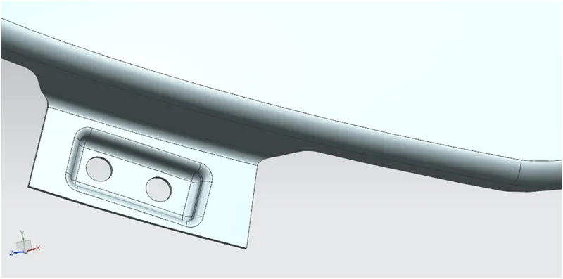
Fig - Bumper Mounting
- Baffle Mounting: This area is to make the holding stronger. This is to provide uniform holding all over the fender. Even the plastic part can be fixed in this region for lining part mounting.
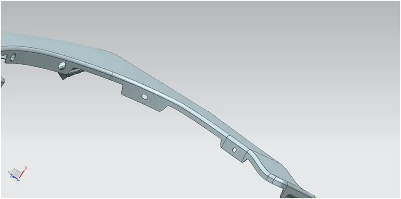
PROCEDURE
- The baffle mounting was designed to fit a splash mounting on it which helps the engine compartment to protect it from the debris that entering in to while driving.
- For creating it three mounting areas were created with the required holes on it for the fasteners.
- For creating the holes, a datum plane was created on all three mountings and projected on to the surface.
- By selecting the required vector and deselecting the project on both side option the holes were created.
- Sill Mounting
Sill mount is a portion fixed to the door sill. Sill is a part of car frame at the bottom.
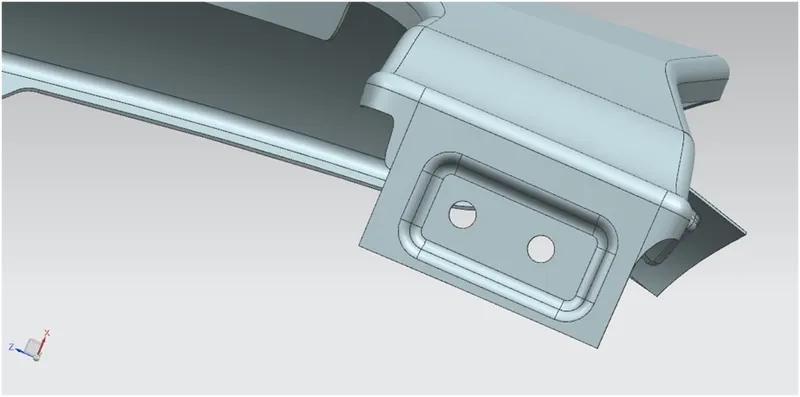
Fig - Sill MountingPROCEDURE
- For creating the sill mounting the extra portions were trimmed out.
- Then the datum was created and the required sketch was drawn and then projected.
- Then emboss were generated and blended the edges together.
- The fastener holes were created by using the trim surface feature.
Manufacturing Process:Fender is manufactured in different stages according to the complicity of the part. Usually the stamping process included are Deep Drawing, Bending, Punching and Trimming.
Deep Drawing:
Deep drawing is a sheet metal forming process in which a sheet metal blank is radially drawn into a forming die by the mechanical action of a punch.
Bending:
It is a process by which metal can be deformed when applying force to the subject, which causes it to bend at an angle and form the anticipated shape, which often results in it being in a V or a 'U' shape.
Punching:
Punching is a machining process that involves the removal of scrap metal from a sheet of raw metal. It requires the use of a punch press to compress a tool through a sheet of raw metal.
Trimming:
Trimming basically presses a part through a cutting die that runs the periphery of the work. The cutting die are precisely designed to remove the flash from a particular part.
Conclusion:
Hence, We learnt about how to design fender in NX-CAD by the given master section and using proper manufacturing processes.