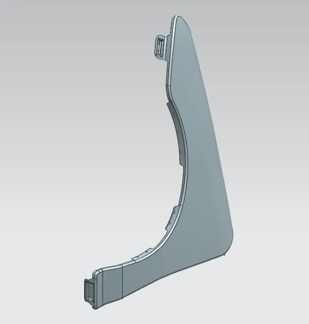
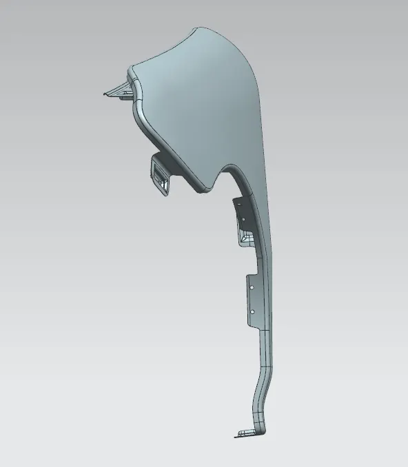
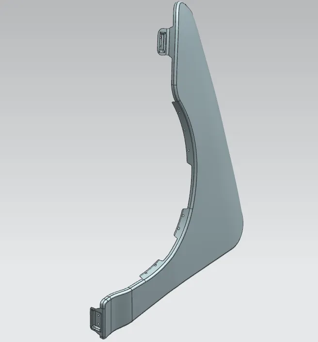
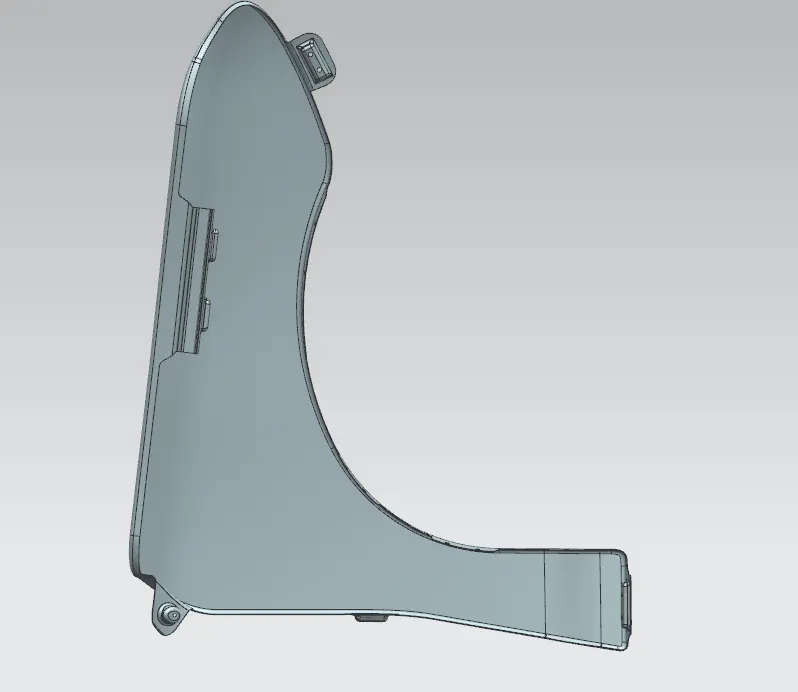
Fender Design
CHALLENGE - FENDER DESIGN
OBJECTIVE: To design a fender using a new age design software - NX - CAD
INTRODUCTION: Any product's design begins with a requirement. Based on the requirements, the design engineer creates a sketch of the product. Using cutting-edge CAD software, the 2D sketch that has the correct dimensions is then turned into a 3D model. Every product that is designed should be able to be made; this is another crucial aspect of design. Therefore, the design engineer's job is to create products that are simple to make and less expensive to produce. This is where design for manufacturing and design for assembly play a part in the development of any product. The design development process continues until the final product meets the needs of the client. The thing that we will create in this project is an automobile fender.
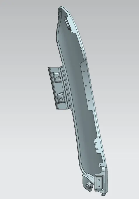
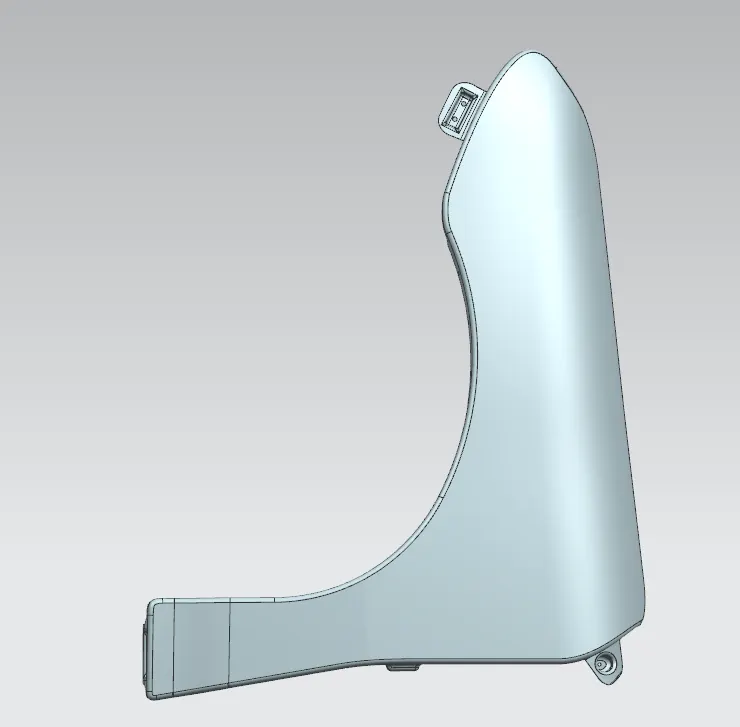
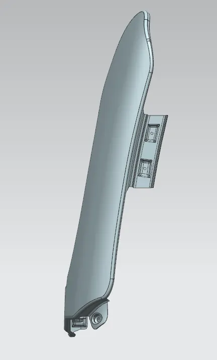
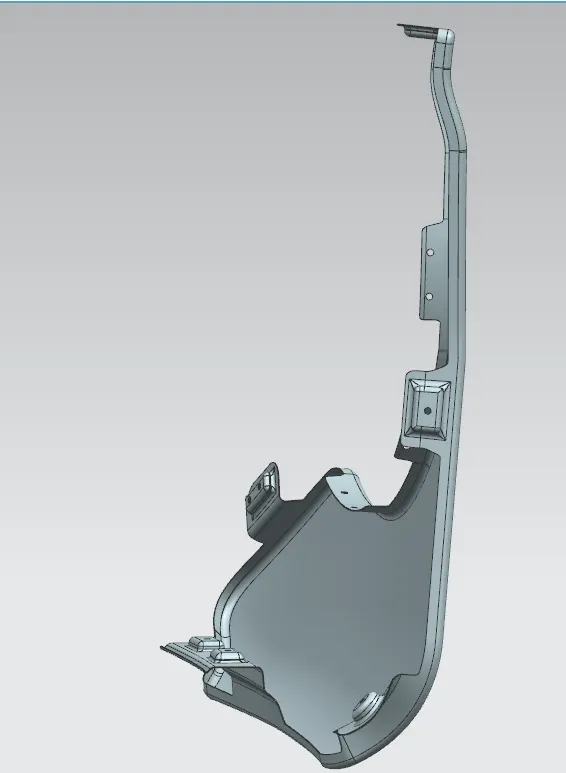
FENDER: The major function of the fender is to stop the revolving tyre from spraying sand, dirt, rocks, liquids, and other road debris into the engine compartment.
TYPES OF FENDERS:
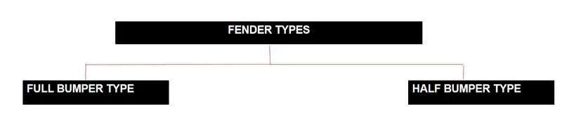
There are two types of fenders, they are
1) Full bumper type
2) Half-bumber type
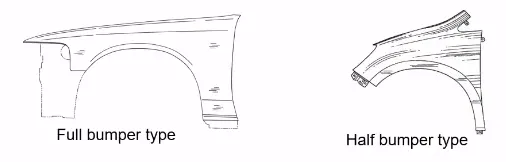
- We currently utilize the half bumper type because, when we choose the full bumper type, the blank used to create it is quite huge and also has a lot of waste. However, with the half-bumper type, we have the option to reduce the scrap. We referred to this as scrap management.
- In the case of the half-bumper design, we utilize more plastic than steel and less of it overall, which boosts performance while also reducing the weight of the vehicle.
FENDER WHEEL ARCH :
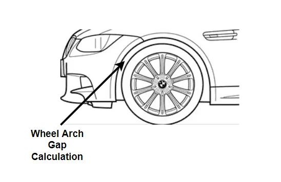
- There are certain requirements for the fender wheel arch, for instance, if you see the automobile from the front, the wheel outside the fender produces more chipping and significant harm to both the car and the pedestrians.
- The tire wheel must be placed inside the fender to preserve the safety of pedestrians.
- The 5mm space between the outermost skin of the fender and the wheel is required by European law.
- Depending on the state of the roads, these standards vary from country to country.
ASSEMBLY :
There are two types of assemblies, which are
- Bottom-up assembly
- Top-down assembly
Bottom-up assembly: The most recommended method for developing assembly models is bottom-up assembly. The components for this kind of assembly are made in part design workbench (as nx cad part) files. Product structure tools are used in the assembly design workbench to create parts. After each component is inserted, constraints are applied to properly position each one in relation to the others in the 3D space. For big assemblies, especially those with complex individual components, this assembly is ideal.
Top-down assembly: Components are generated inside the assembly design workbench using the top assembly design approach. As a result, it is unnecessary to make separate part files for the components. The bottom-up design technique is entirely different from this one. Here, you must first build the product file before creating each component one at a time. Keep in mind that even then, the pieces are created in the product file and saved and opened one by one as needed. Here, construction and assembly are done concurrently.
MOUNTING REGIONS ON FENDER :
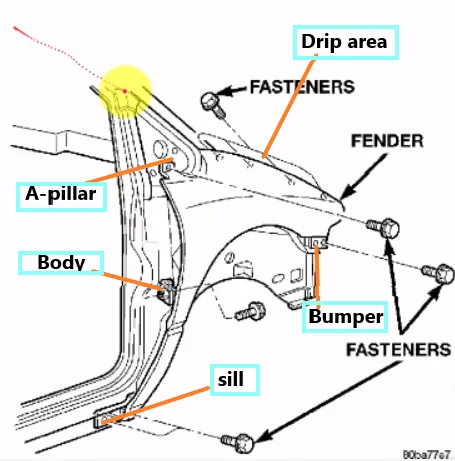
There are 5 mounting regions on the fender, they are
- A- pillar mounting
- Body mounting
- Sill mounting
- Bumper mounting
- Drip mounting
DESIGN METHODOLOGY :
GIVEN DATA :
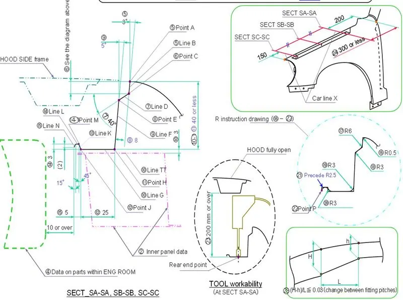
MASTER SECTION
DESIGN 0F DRIP AREA MOUNTING :
- It is the crucial component that holds the fender in place. As a result of its connection to the engine compartment, the fender must adhere to certain design restrictions
- We need to initially leave 200-300 mm for the cowl top when building the drip region.
- When creating the fender, we must leave at least 150 mm at the front for mounting the headlamp.
- The wiper motor and associated instruments are located in the cowl top portion.
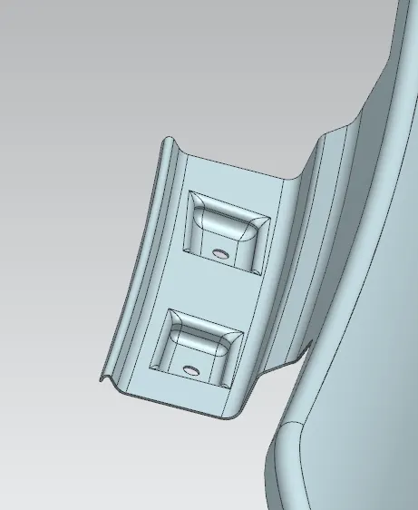
DRIP AREA
- Embossing is provided on the mounting to strengthen them during fastening.
DESIGN OF SILL MOUNTING AREA :
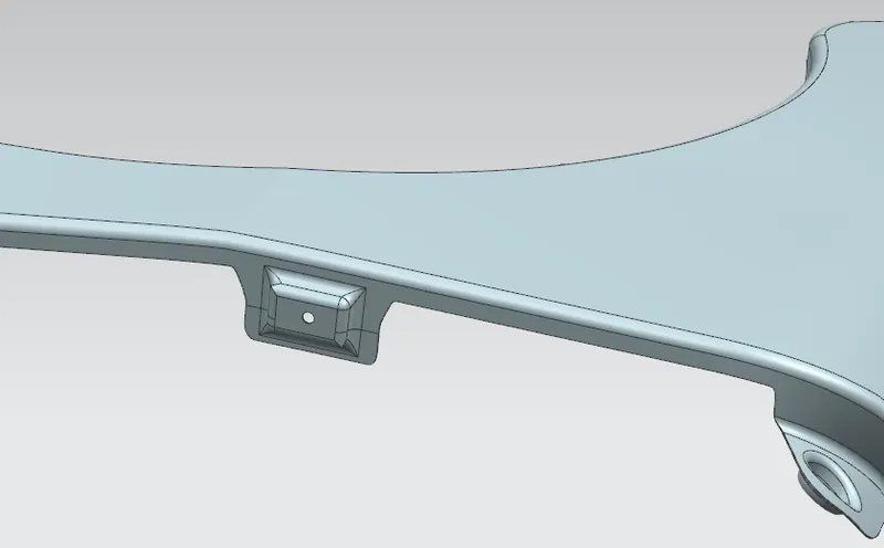
The sill is the panel directly below the bottom of the door supporting the floor and may be used to combine the floor and the body. The bottom end of the fender is mounted on the sill body for reinforcement of the fender panel, thus the sill mounting position is designed with holes and emboss.
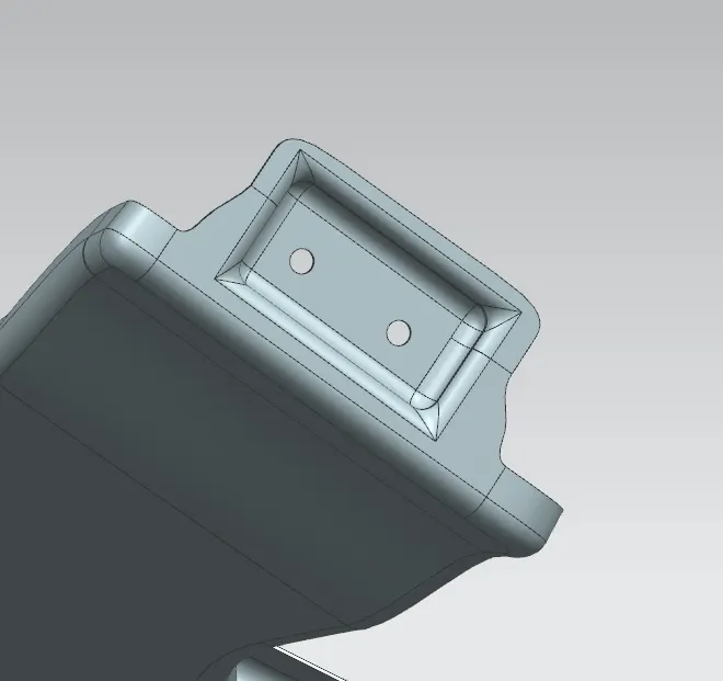
SILL MOUNTING
DESIGN OF BUMPER MOUNTING AREA :
The bumper mounting area is used to fix the plastic bumper to the fender with the help of the fasteners
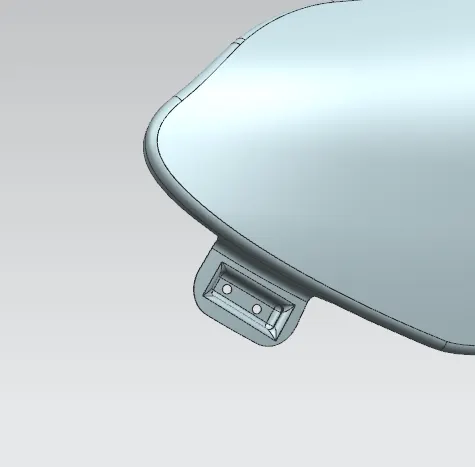
BUMPER MOUNTING
DESIGN OF A-PILLAR MOUNTING AREA :
The A-pillar is the structural pillar that combines the body with the roof. This makes the sides of the windshield rest. Front fenders are fastened to the A-pillar to form a robust structure.
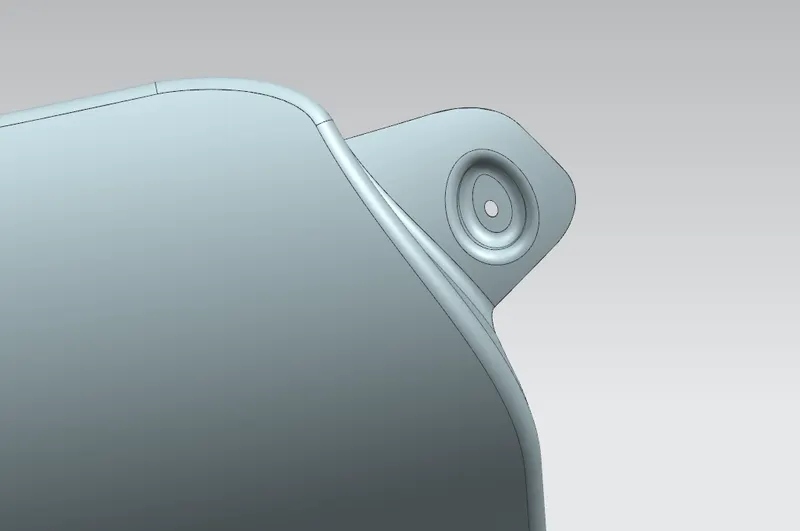
A-PILLAR MOUNTING
DESIGN OF BAFFLE MOUNTING AREA :
Baffle mounting or mudguard are clip-fit types of mounting on the inner side of the fender arch over the Tyre. It protects the car engine compartment and pedestrians from causing injuries from chip-out debris on the road when the car is in motion. They are mounted on the fender using a special type of locking clips which are made up of plastics.
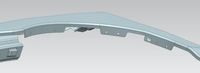
DESIGN OF BODY MOUNTING AREA:
Different Oientations: