Week 2- 2R Robotic Arm Challenge
2R ROBOTIC ARM
AIM: To simulate the forward kinematics of a 2R Robotic Arm by creating a MATLAB program.
OBJECTIVE: To create an animation of the simulation
Theory:
Robotic Arm – A robotic arm is a type of mechanical arm, usually programmable, with similar functions to a human arm; the arm may be the sum total of the mechanism or may be part of a more complex robot. The links of such a manipulator are connected by joints allowing either rotational motion (such as in an articulated robot) or translational (linear) displacement. The links of the manipulator can be considered to form a kinematic chain. The terminus of the kinematic chain of the manipulator is called the end effector and it is analogous to the human hand.
INPUTS:
- Length of the Links
Let, Length of the link (l1) is l1 = 1 (m)
And, Length of the link (l2) is l2 = 0.5 (m)
- Co-ordinates of X & Y of Links 1 and 2
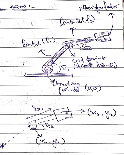
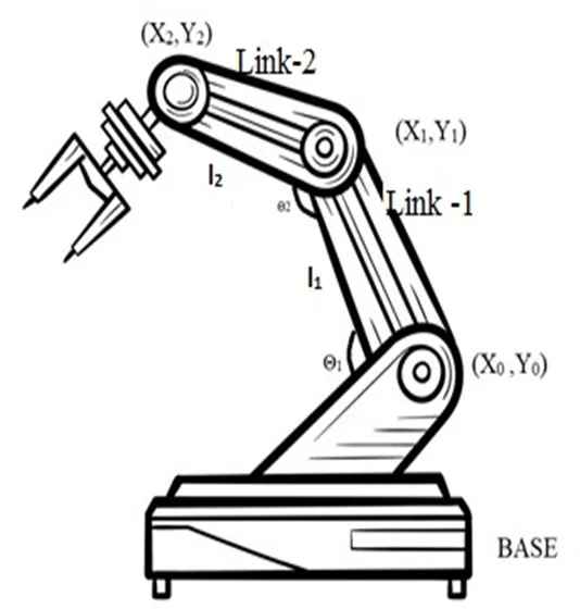
(X0,Y0) : The starting point of the first link i.e., link 1 is attached to the base as the base is fixed, so the starting point of the link 1 cannot move as it is fixed position, so the value of X and Y will be 0.
i.e., X0 = 0
Y0 = 0
(X1,Y1) : The ending point of the link 1 is the starting point of the link 2. The length of link 1 is l1 and the angle between the base and link 1 is represented by an angle θ1θ1.
Therefore, X1 = l1*cosd(θ1)
Y1 = l1*sind(θ1)
(X2,Y2): It is the ending point of link 2. The angle between link 1 and link 2 It is represented by an angle θ2θ2 and length of link 2 is l2.
Therefore, X2 = X1+l2*cosd(θ2)
Y2 = Y1+l2*sind(θ2)
CODE:
%Forward kinematics of a 2R Robotic Arm Manipulator
clear all
close all
clc

% Inputs
% Link lengths
l1 = 1; % Assuming a length of link 1 as 1m
l2 = 0.5; % Assuming a length of link 2 as 0.5m

% Angle between the links
theta1 = linspace(0,90,40); % Angle of traverse of first link
theta2 = linspace(0,90,40); % Angle of traverse of second link

ct=1;
for i = 1:length(theta1)
    THETA1 = theta1(i);
    for j = 1:length(theta2)
        THETA2 = theta2(j);
        X0 = 0; % x coordinate of the start point of link 1
        Y0 = 0; % y coordinate of the start point of link 1

        X1 = l1*cosd(THETA1); % x coordinate of the end point of link 1
        Y1 = l1*sind(THETA1); % y coordinate of the end point of link 1

        X2 = X1+l2*cosd(THETA2); % x coordinate of the end point of link 2
        Y2 = Y1+l2*sind(THETA2); % y coordinate of the end point of link 2

        % Plotting
        plot([X0 X1], [Y0 Y1],[X1 X2], [Y1 Y2],'linewidth',3) % plotting the x and y axis coordinates
        axis([-0.1 1.5 0 1.5]) % plotting the x and y axis coordinates
        pause(0.01) % pause time for each frame
        M(ct) = getframe(gcf); % for creating the animation
        ct=ct+1; %frame of increment 1
    end
end

movie(M)
videofile = VideoWriter('forward_kinematics.avi','Uncompressed AVI');
open(videofile)
writeVideo(videofile,M)
close(videofile)
Explanation:
- MATLAB code is started with clear all, close all, and clc command.
clear all: is used to clear all the data stored in the workplace.
close all: is used to close all the figures and close plots.
clc: is used to clear the command window.
- The input value for θ1 and θ2 is determined with a command linspace in this we create a degree of freedom from 0 to 90 with 10 values between the degree of freedom.
- Then initialize the counter command using ct.
- To move the robotic arm continuously, we are using for loop.
for i = 1:length(theta1)
THETA1 = theta1(i);
for j = 1:length(theta2)
THETA2 = theta2(j);
The value of ‘i’ is going to change from 1 to length of θ1 and value of ‘j’ is going to change from 1 to length of θ2. Here, as the values of ‘i’ and ‘j’ changes then angles θ1 and θ2 are taken from original arrays and are assigned to variables ‘THETA1’ and ‘THETA2’ which contains only one value and not an array, loop counter variables are used to access particular value. For each value of θ1 i.e., each position of link 1 and link 2 can take multiple positions depends on θ2.
- Then enter the values of co-ordinates ([X0 X1], [Y0 Y1],[X1 X2], [Y1 Y2]).
- Then plot the values of ([X0 X1], [Y0 Y1],[X1 X2], [Y1 Y2]) with the 'linewidth',3.
- Then axis command is used for fixing axes - changing x-limits and y-limits.
- Then use pause command to slow down the output.
- Then we use getframe command to get individual frame and stored in variable M.
- Then incrementing the counter value by 1.
- The end command is used to end the for loops, this terminates the set of instructions.
- Using movie command we can create a movie with the help of individual frame.
- Using the different individual frames a new uncompressed avi file is created using videofile command.
- Then we are opening the videofile using the open command and closing the videofile using the close command.
OUTPUT ANIMATION:
YouTube Link – https://youtu.be/6Lct_M7C9Dk
Errors:
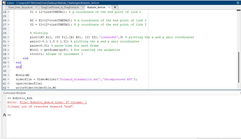
Solution – Removed the end keyword from line no. 37