Fender Design
FENDER DESIGN
Fender covers a BIW body, traditionally to prevent water and mud spray entering the engine compartment, but also for aerodynamic purposes. When the vehicle is moving tyre picks up stones & particles are thrown in all direction, also in order to prevent impact on pedestrians hence wheel arch is used on fenders.
Fender is of two types front and Rear fender, The front fenders are designed as an individual part and the back fenders are designed along with the body pillars.
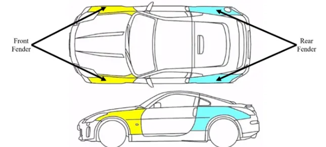
Typical Needs of Fender:
- It is designed to provide resistance against wind, muds, and foreign particles.
- It is the sheet of metal covering of the car providing better Aerodynamics to reduce drag co-efficient.
- Fender has a plastic part called Baffle or fender Liner which fits underside the fender to protect the metal from corrosion by stopping the flow of mud and water inside from different weather conditions.
There are 2 types of fenders.
- Full Bumper Type
- Half Bumper Type
Full Bumper Type:
Full Bumper Type is not used now a days because it requires large size of sheet metal for stamping to produce the part reflecting increase in production cost.
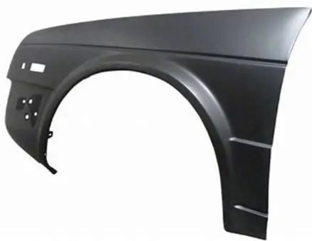
Half Bumper Type:
Half bumper is used because the waste of material is less & can produce two fender front single sheet metal thereby reducing time and cost effective.
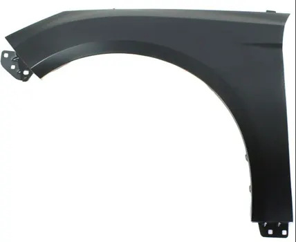
Fender Design:
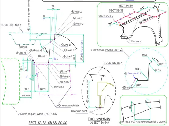
With the given Master section design the mounting for the front fender.
We can create our own design according to the Engineering standard.
Areas to be designed:
- Drip Mounting
- Sill Mounting
- Bumper Mounting
- Baffle Mounting
- A-Pillar Mounting
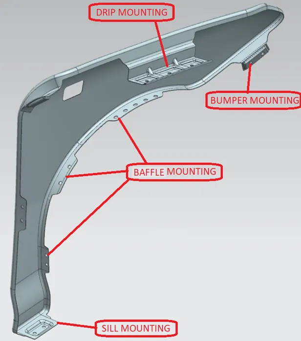
- Drip Mounting:
- Front fender is bolted to engine housing through the drip area.
- There are some considerations to be followed for designing the drip area especially accessibility.
- Here the considerations to be taken followed by the given master section.
- A min of 150mm distance is kept from the front end and 300mm or less from the rear side.
- This clearance is provided to avoid the spring back during the manufacturing. the edge of the mounting should at least 10mm away from any nearby component in the engine.
- Overall drip area should be less than 40mm deep.
- The embosses that are created on the drip mounting should be flat with respect to the curvature. This is to provide flat contact with the mating component.
- A dart is provided at the edge of the drip mounting to increase the stiffness.
Steps:
- Offset outer edge to 5mm inside
- Create 2 datum plane from front and rear edge of the fender.
- Use curve on surface to create a curve on the intersection plane.
- Trim unnecessary parts.
- As per the master section create a flange area using Law extension feature.
- After the flanges, create dart for stiffening the flanges.
- Create a sketch for the emboss, with 10 mm clearance for the stiffeners.
- Create a emboss with the bottom flat for sake of mating with the Engine mount.
- Project the sketch and Trim for Holes.
- Provide Edge and face blends to smoothen the surface.
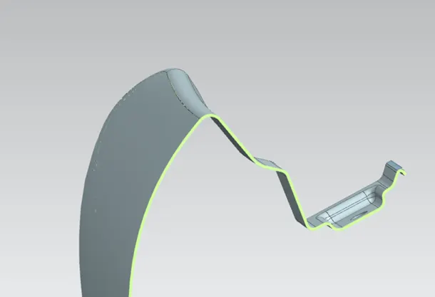
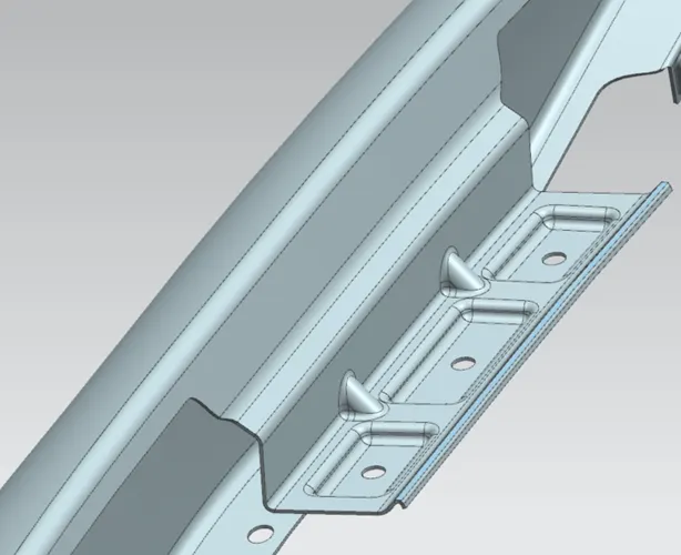
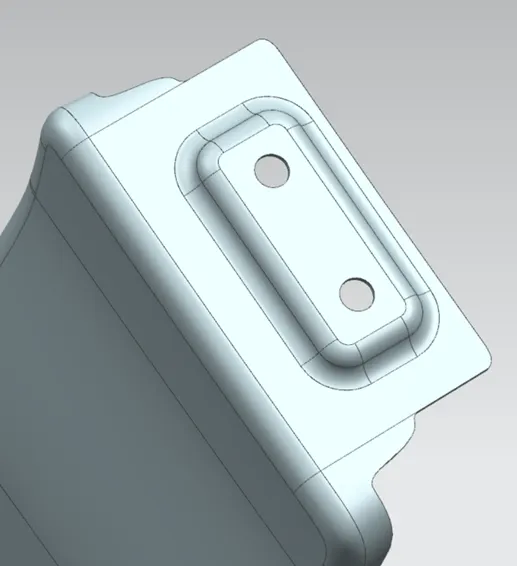
- Sill Mounting:
Sill mounting is placed at the bottom of the fender. The mounting part is created such that it firmly fits to the sill.
Steps:
- Use curve of surface feature to get the mount.
- Avoid sharp edge which cause manufacturing difficulties.
- Use bridge curve to create round edge for sharp corner and Trim sheet to cut.
- Create new Plane for the emboss sketch. Emboss should be flat at the bottom for sake of flat contact with sill.
- Fasteners should have 10mm clearance.
- Project the sketch and Trim for Holes.
- Create emboss and provide edge blends t smoothen the surface.
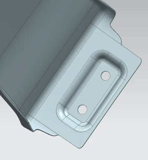
3. Bumper Mounting:
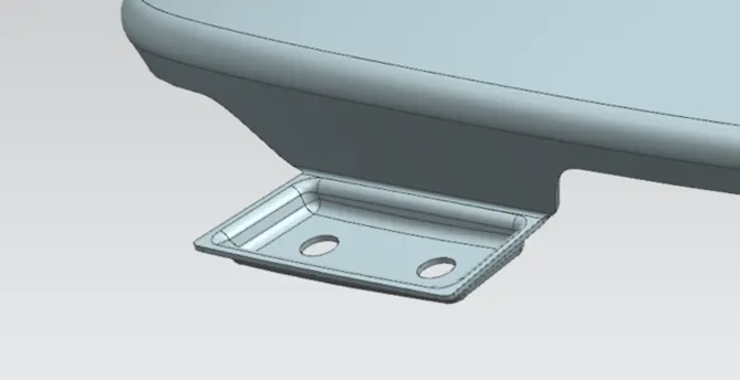
It provides mounting for the bumper, sometimes it provides housing for headlight assembly.
Steps:
- Use surface to obtain flange for the mount.
- Using Law extension obtain the second flange.
- Remove sharp edges with bridge curve and Trim sheet feature.
- Create new datum plane for the emboss sketch.
- Project sketch on to the surface and create emboss.
- Emboss should be flat and smoothen the edges with blends.
- Project the sketch and Trim for Holes.
- Baffle Mounting:
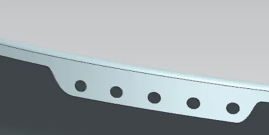
Baffle is used for inhibiting the passage of sound, debris or the like through a cavity of an automotive vehicle characterised by combining metal and synthetic material a foam synthetic material or metal being added as insulation.
Steps:
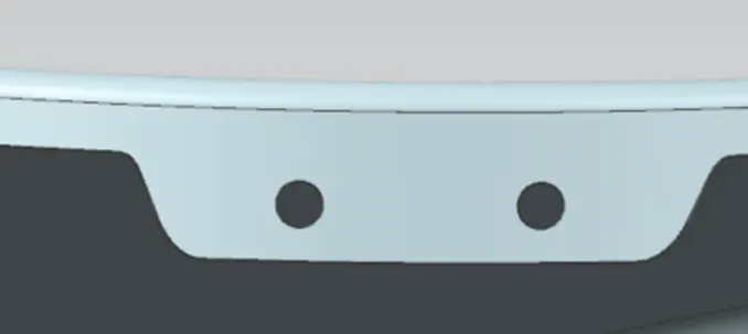
- Create curve on surface and trim to have multiple small flanges for Baffle mounting.
- Create datum plane for each flange for draw circles for holes.
- Use projection curve and trim sheet to draw holes on to the baffle mount.
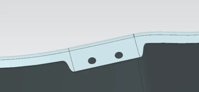
- A-Pillar Mounting:
This mount helps to bolt-up the fender on to the A-pillar. A-Pillar is the structure of the monocoque chassis.
Steps:
- Use curve on surface to create flange.
- Use law extension to create second flange.
- Create a datum plane and Create sketch for emboss and project on to the surface.
- Create emboss with flat surface and smoothen with blends.
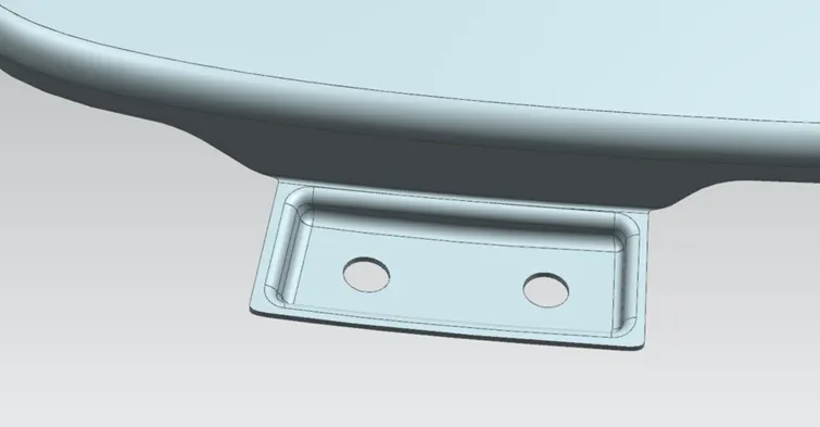
Cutout For Indicator: Create sketch and trim for Indicator cutout.
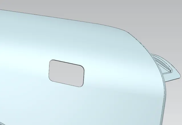
Final Use thicken for 0.75mm to provide thickness for the part.
We have designe the mounting as per the requirements.