Exhaust Port Challenge
Conjugate Heat Transfer:
The term conjugate heat transfer (CHT) is used to describe processes which involve variations of temperature within solids and fluids, due to thermal interaction between the solids and fluids. The exchange of thermal energy between the two physical bodies is called study of Heat Transfer, the rate of transferred heat is directly proportional to the temperature difference between the bodies. A typical example is the heating or cooling of a solid object by the flow of air in which it is immersed and some other example includes conduction through solids, free and forced convection in the gases/fluids and thermal radiation.
Conjugate heat transfer corresponds with the combination of heat transfer in solids and heat transfer in fluids. In solids, conduction often dominates whereas in fluids, convection usually dominates. Efficiently combining heat transfer in fluids and solids is the key to designing effective coolers, heaters, or heat exchangers. Forced convection is the most common way to achieve high heat transfer rate. In some applications, the performances are further improved by combining convection with phase change (for example liquid water to vapor phase change).
Heat transfer in solids and heat transfer in fluids are combined in the majority of applications. This is because fluids flow around solids or between solid walls, and because solids are usually immersed in a fluid.
The Conjugate Heat Transfer (CHT) analysis type allows for the simulation of heat transfer between solid and fluid domains by exchanging thermal energy at the interfaces between them.
Conjugate Heat Transfer analysis provides the temperature distribution in solid and coolant of the engine and clear insight on velocity distribution and mechanism of heat transfer of coolant
CHT can be performed to improve cooling performance of the water jacket and increase engine life
Results of CHT analysis become input to structural simulations as thermal loads.
Procedure:
Geometry Preperation:
- The exhaust port geometry was imported into Spaceclaim.By using the extract volume command the inner fluid volume(where air flow takes place) was extracted.
- The exterior body was set to solid volume.The solid and fluid volume was exported as new component
- The topology was set to share so as to obtain conformal mesh
Meshing:
- The global mesh size was set to 70mm
- Body sizing was provided to the solid volume to capture heat transfer accurately with element size of 20mm
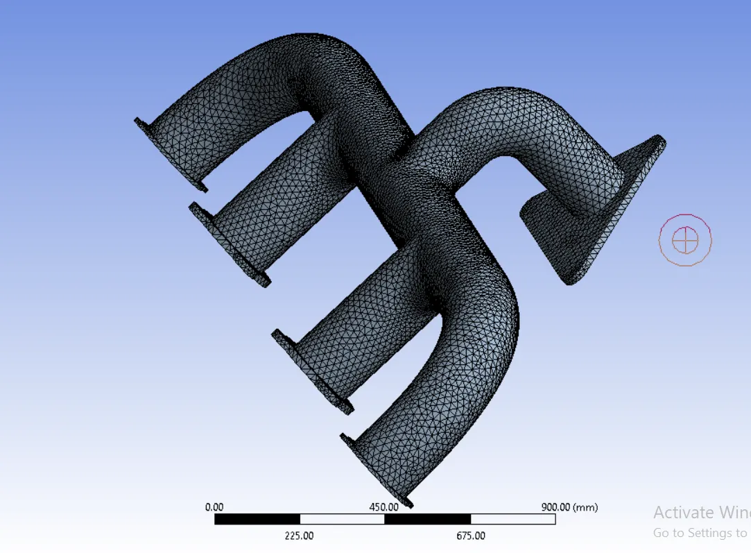
- Inflation layers are added to predict wall heat transfer coefficient.The first layer thickness of inflation layer depends upon the turbulence model selected,length of fluid flow,density,viscosity and velocity of fluid flow
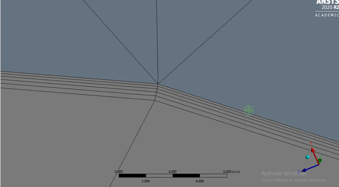
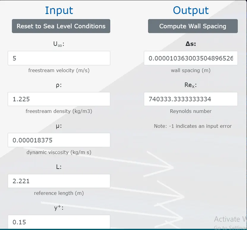
- Here k-omega SST model is selected so the wall y+ should be in the range of 0-5
- The first layer thickness is calculated as shown below which is 1.0363e-5m
Solution Setup
- As we have to solve for temperature the energy equation is switched on
- The turbulence model is set to k-omega SST
- Aluminium is selected as the material for solid and air is selected as the working fluid
- Boundary conditions : Inlet is set as velocity inlet with Inlet velocity=5m/s Inlet temperature=700K
Outlet is set as pressure oulet with 0 gage pressure
The outer wall which is exposed to surrounding air is set as convective wall with convective heat transfer coefficient as 20 W/m^2K
The remaining surfaces are set to adiabatic condition i.e heat flux=0 W/m^2
- Hybrid intialisation is done and the solution is run for 200 iterations
- A report for wall adjacent heat transfer coefficient is created for the inner wall
Solution and Post Processing
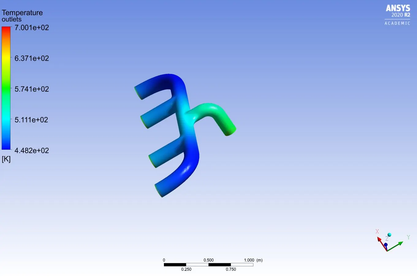
- Following temperature contour of exterior wall is obtained
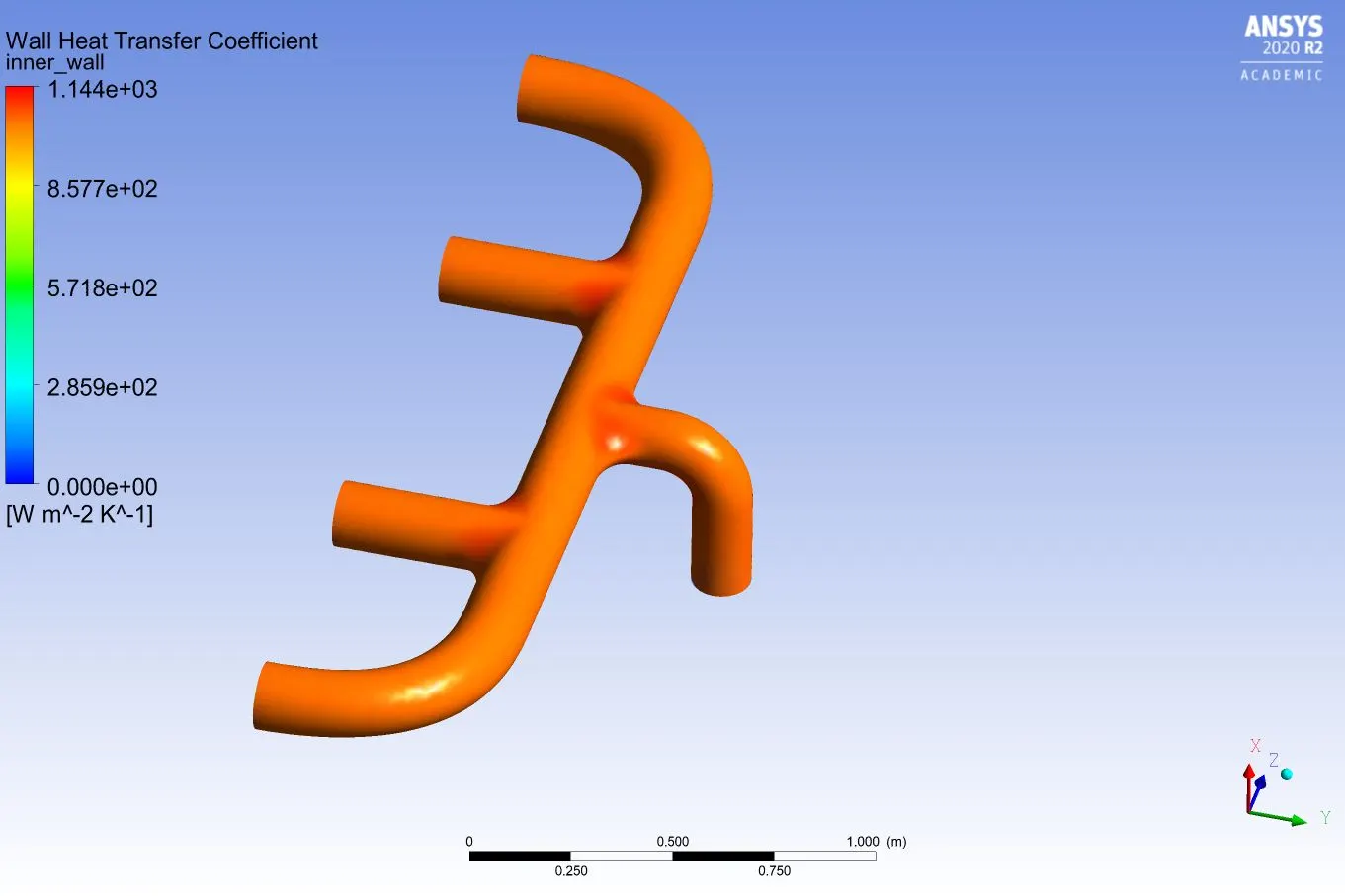
- The contour for wall heat transfer coefficient at the interior surface is shown below
- Velocity streamline is shown below( Velocity is maximum at the outlet port)
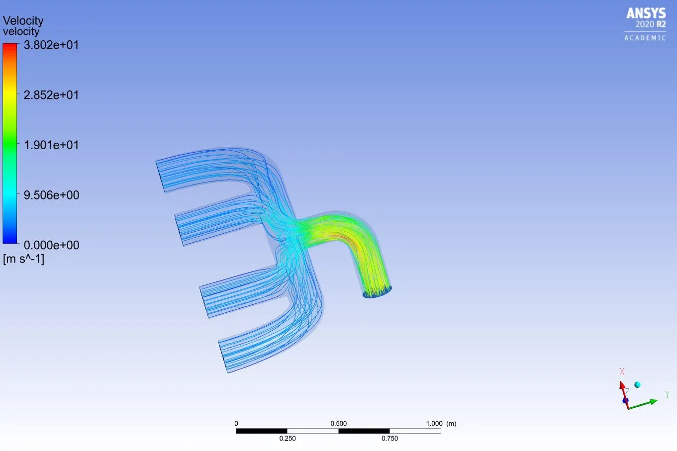
- The heat tranfer coefficient was found out to be 1051.56 W/m^2K and from the contour we can say that it is maximum at the outlet port the reason is as the air coming from all the inlet port gets mixed its velocity increases this increases the Reynolds number thus increases the wall htc
Conclusions
- The correct prediction of htc depends upon the wall y+ selected.As y+ determines the first layer thickness,smaller the first layer thickness more accurate will be the wall htc.From experiments it was found out for the above physical condition htc value lies in the range of 970-1200 W/m^2K.We have obatined an htc of 1051.56 W/m^2K so our prediction is correct
- From the contour we can say that temperature and htc is maximum at the outlet port the reason is as the air coming from all the inlet port gets mixed,its velocity increases this increases the Reynolds number thus increases the wall htc
- y+ selection depends on the turbulence model selected for
k-omega 0-5
k-epsilon 30-300
for precise prediction we selected the k-omega model