Engine wiring harness design
Aim: Route the Wiring harness on Given Engine and Prepare flattened view drawing in CATIA V5. Application of all Packaging rules, Industry best practices studied in this course shall be demonstrated in design
- All the required parts are downloaded from Tyco connectivity
- Couplers are defined as connectors and bundle entry and connector connectivity points are defined
- Wiring channels are defined as equipments and bundle routings are defined
- P clamps and Fir tree clips are defined as supports.
- All of the above are done in electrical part design workbench
- After defining all parts, move to assembly workbench by creating 2 products - Engine wiring harness context assy and wiring harness geometrical bundle.
- Select geometrical bundle and place parts and connectors in their suitable locations
- after placing them activate the geometrical bundle command and start routing bundles
- After routing verify continuity and proceed to wiring harness flattening
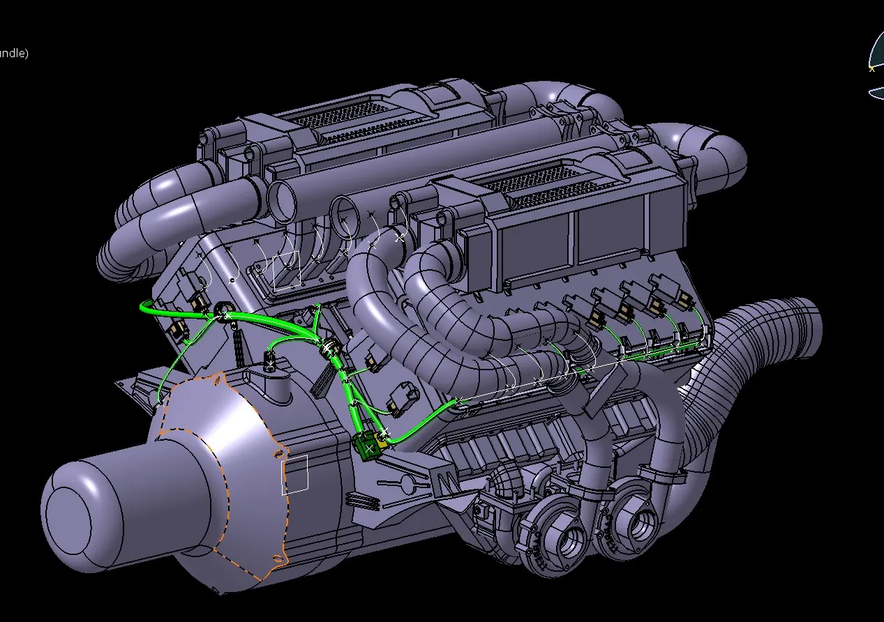
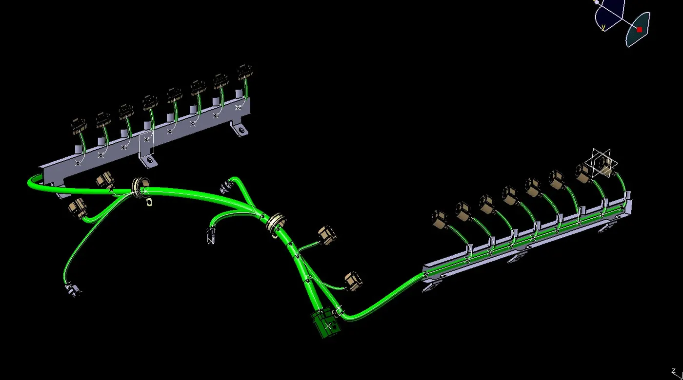
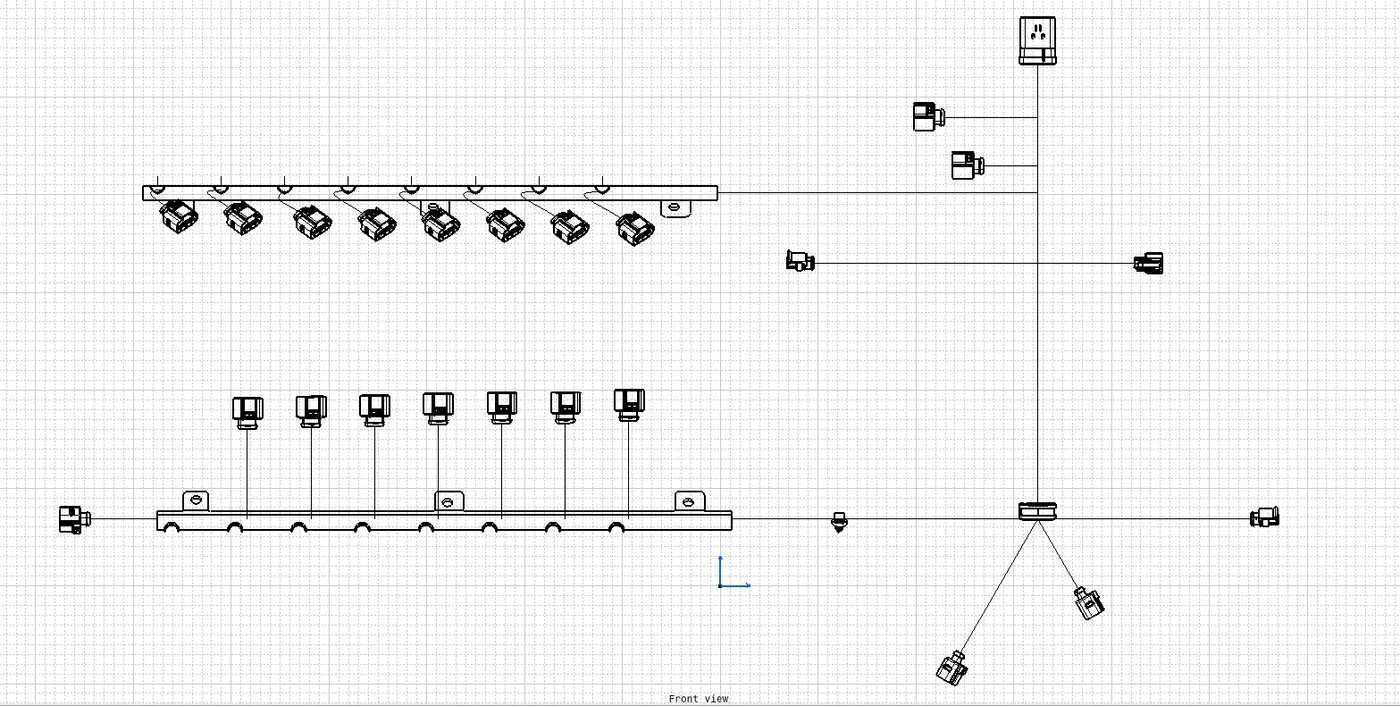
[NB - File too large to upload with the engine assy included, therefore uploaded file without engine assy in challenge and complete file for reference is available in the below linked google drive https://drive.google.com/drive/folders/1EE_kSO6ZVOYL-IrUmJPQGt1AzOfYFulf?usp=sharing]