Week 10 - Challenge 1- Attachment Feature Creation (Ribs & Screw Boss)
Tooling Axis
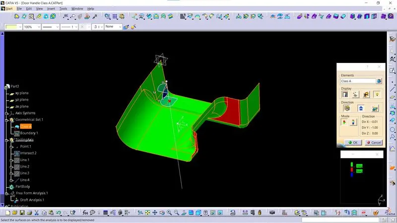
- To create the tooling axis, I began by extracting the surface of Class A without any propagation. Next, I generated a point at the center of the extracted surface and created a line extending in the Y direction from that point. With the tooling axis now established, I proceeded to conduct a draft analysis on Class A
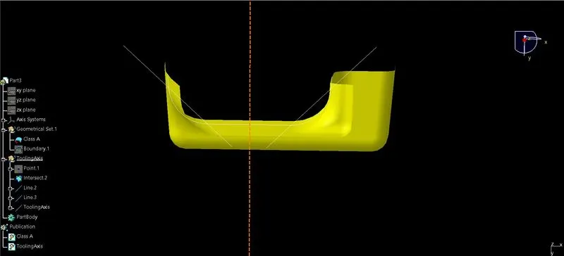
Class A draft analysis
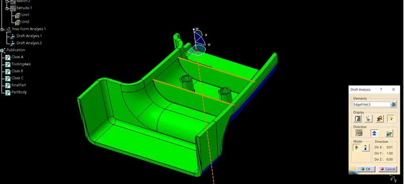
- To execute the draft analysis in Class A, I utilized the featured draft analysis tool available in the Generative shape design workbench. Initially, I selected the 'use of the compass to define the new current draft direction command
- When the Class A surface is chosen, it will be highlighted in green color based on the color bar angle and colors that were previously defined. The color representation allows for a clear visualization of the draft angles present on the surface, with different colors indicating varying angles as per the defined color bar.
Surface Modelling
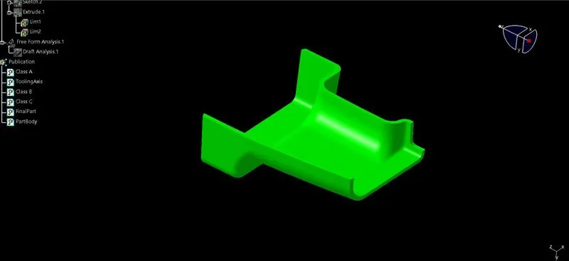
- To generate the Class B surface for the door handle, the Class A surface was offset by 2.5mm inward. However, after the offset operation, some patches became visible on the offset surface due to the presence of fillets on the Class A surface. To address this issue, the patches needed to be closed. To accomplish this, the "multi-section solid" command was utilized. This command allows for the creation of a solid surface by defining multiple sections, enabling the closure of the patches and producing a continuous and smooth Class B surface for the door handle design.
- To create the Class C surface, the boundary of Class A was selected, and a sweeping operation was performed in the direction of the tooling axis. The sweeping action was done at a 90-degree angle in certain areas and at a 3-degree angle in other required areas
- After sweeping the patches, the next step involved trimming the swept patches to fit the Class A surface properly. Once trimmed, the swept patches were joined with the Class A surface. Subsequently, the final surface was obtained by trimming the combined surface (Class A with joined swept patches) with the Class B surface
Rib and Screw Boss
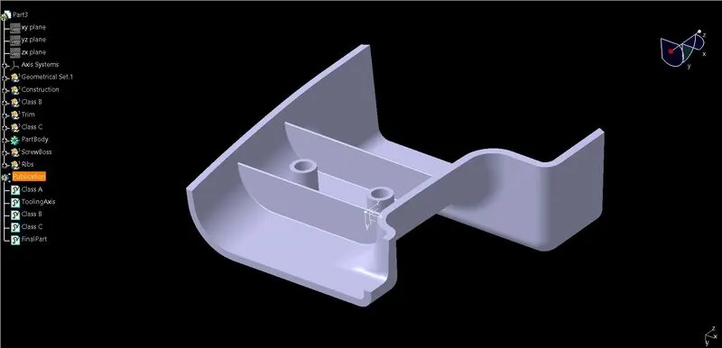
- To create ribs, a positioning sketch was first created on the surface. In this sketch, two lines were drawn representing the desired rib locations. These lines were then extruded to a height of 6 times the thickness of the base, which is 2.5mm. After extrusion, the ribs were thickened by an additional 1mm
- Following the extrusion and thickening of the ribs, the next step was to apply a draft of 0.5 degrees to the ribs. This draft helps ensure that the ribs can be easily removed from the mold during the manufacturing process. After drafting, the ribs were filleted with a radius of 0.25mm. The filleting process rounds the edges of the ribs, providing a smoother surface and preventing sharp corners
- In the process of creating the screw boss, two concentric circles of 5mm and 8mm were drawn, and they were then extruded to a height equivalent to 3 times the width of the base. To facilitate mold release during manufacturing, a draft of 0.5 degrees was applied to both sides of the extruded shape. Additionally, the edges of the screw boss were filleted with a radius of 0.25mm to ensure smoother transitions between surface