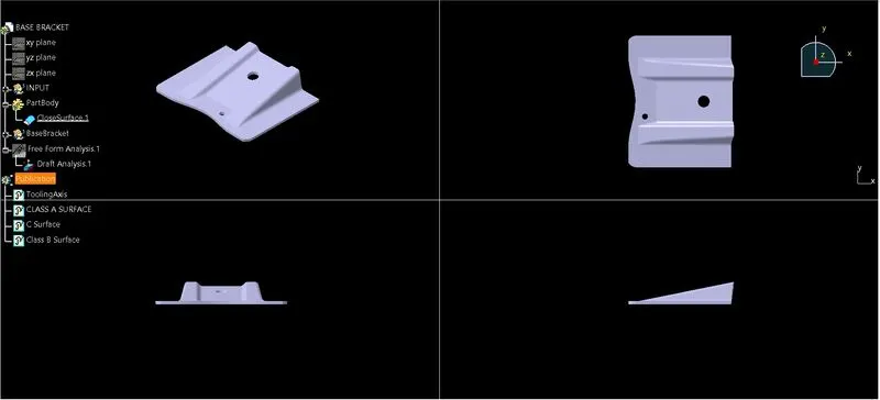
Week 9 - Challenge 1 - Base Bracket Design
Tooling axis generation
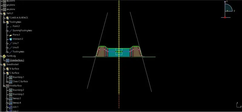
- Upon careful examination of the Class A surface, it became evident that both the flat surface and the holes were situated in the xy plane. Consequently, a decoy tooling axis was created perpendicular to this plane
- The plane perpendicular to the primary hole served as a reference point for utilizing the intersect command
- The tooling axis was generated by constructing the bisector of the two lines extending from each point of the inclined lines that intersected with the reference plane. This approach ensured that the tooling axis was properly aligned and provided optimal orientation for further manufacturing processes
- In this particular case, the tooling axis was not created using inclinations in the x direction since there were no obstructions that could hinder the injection process. Instead, an alternative method was employed to establish the tooling axis, ensuring efficient and unobstructed manufacturing of the component
- If there were surfaces with specific inclinations, the lines projected from those inclined surfaces would have been employed to create an additional bisector. This newly derived bisector would serve as the tool clearing axis in the x direction
Draft analysis
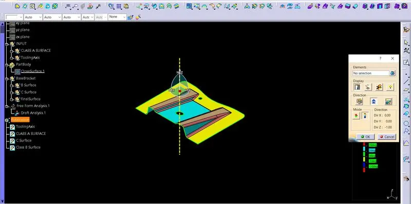
- The Class A surface undergoes a thorough draft analysis to verify and assess the angle of draft specified. This analysis ensures that the surface meets the required draft angle
- The drafting direction is determined using a compass
- After selecting the surface, the color grade can be utilized to quickly identify the angle of draft. The colors assigned to different areas on the surface provide a visual representation of the draft angle variations. This allows for a rapid overview and understanding of the draft analysis results
- Moreover, the analysis can be performed under running mode, enabling a manual inspection of each surface. This hands-on approach allows for a detailed examination of individual surfaces, providing a more in-depth assessment of the draft angles and ensuring any potential issues are thoroughly reviewed and addressed
3D Modelling
- Following the tooling axis generation and draft analysis, each individual surface of the Class A surface is extracted. This extraction process involves isolating and segregating each surface separately
- Each surface is untrimmed and extrapolated, and subsequently, each surface is trimmed according to the Class A surface. This step results in the final Class B surface. The process ensures that the Class B surface aligns precisely with the Class A surface
- Next, the boundary tool is employed along the boundary of the Class A surface. It is then swept along the tooling axis, adhering to a draft angle of 3 degrees. This process generates the Class C surface, which joins the existing Class A and Class B surfaces
- Subsequently, the Class A and Class C surfaces are joined together, seamlessly merging their geometry. The joined surfaces are then trimmed along the Class B surface geometry, creating a unified component
- Thus the final closed component is ready