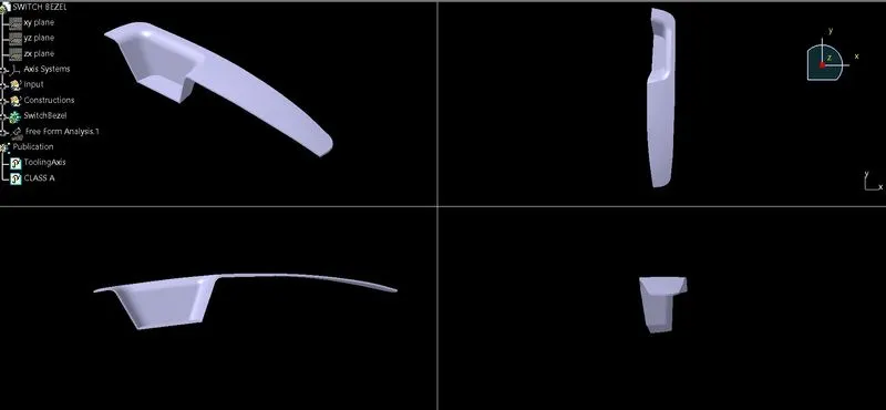
Week 9 - Challenge 2 - Switch Bezel Design
Tooling Axis
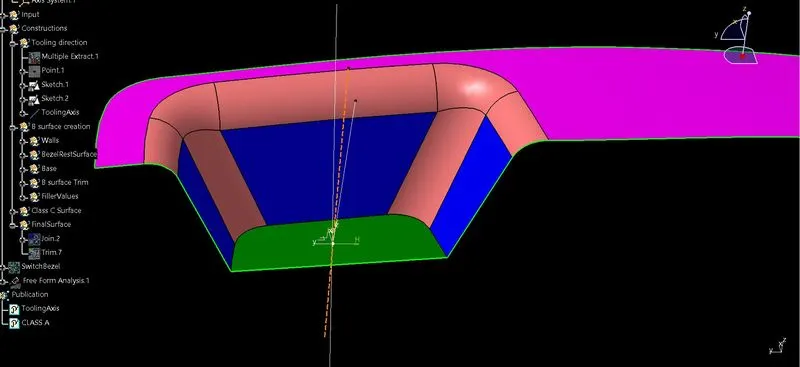
- A point was established on the base to serve as a reference, from which two planes were created perpendicular to the x and y axes, respectively. Subsequently, the A surface was intersected by the plane oriented parallel to the y direction
- To create the tooling axis in the y direction, the two inclined lines were taken and bisected along the initial reference point
- Afterward, the lines intersected by the other plane were utilized to create a single line. Another line was manually generated, adjusting its angle to ensure that the inclined surface obtained a minimum draft of 3 degrees
- Following that, the two lines were bisected to form the tooling axis in the x direction
- The two tooling axes in the x and y directions were further bisected, resulting in the final tooling axis for the given Class-A surface
Draft analysis
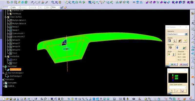
- Once the final product were established, a draft analysis was conducted to assess and ensure that the design meets the required draft angles
- The draft axis tool was aligned and coincided with the established tooling axis. To examine the different draft angles across the surfaces, a color chart was referenced, providing a visual representation of the draft angles
3D Model
- After completing the tooling axis generation and draft analysis, the next step involves extracting each individual surface of the Class-A surface. This extraction process entails isolating and segregating each surface separately
- Each surfaces are the extrapolated and offset by 2.5mm.
- The offset surfaces are then trimmed according to the class A surface, resulting in class b surface
- Finally the class A surface boundary is swept along the tooling axis to produce class C surface
- Finally the closed component is ready for manufacturing