Engine Compartment Project
-: ENGINE COMPORTMENT :-
OBJECTIVE:
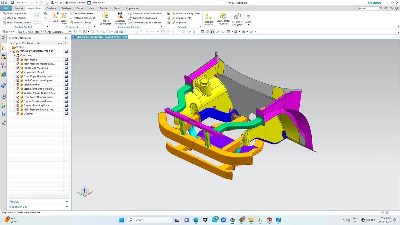
Apart from this all the mounting parts for attaching components are provided by the engine compartment integral to the chassis structure, the engine compartment consist of the assemplies and sub assemblies that forms the frontal structure.
The Main Structure Are:
- Main Chassis Structure
- Suspension Mounting
- Front Bumper Assemply
- Fender Side Mounting
- Lower Chassis Structure
- Lower Engine Mount
DESIGN REQUIREMENTS:
- Designed to take up the side impact, on the engine compartment area as well as frontal offset crash load upon frontal impact.
- It hold the front fender in place with mountings and acts as a reinforcement.
MAIN FRAME STRUCTURE:
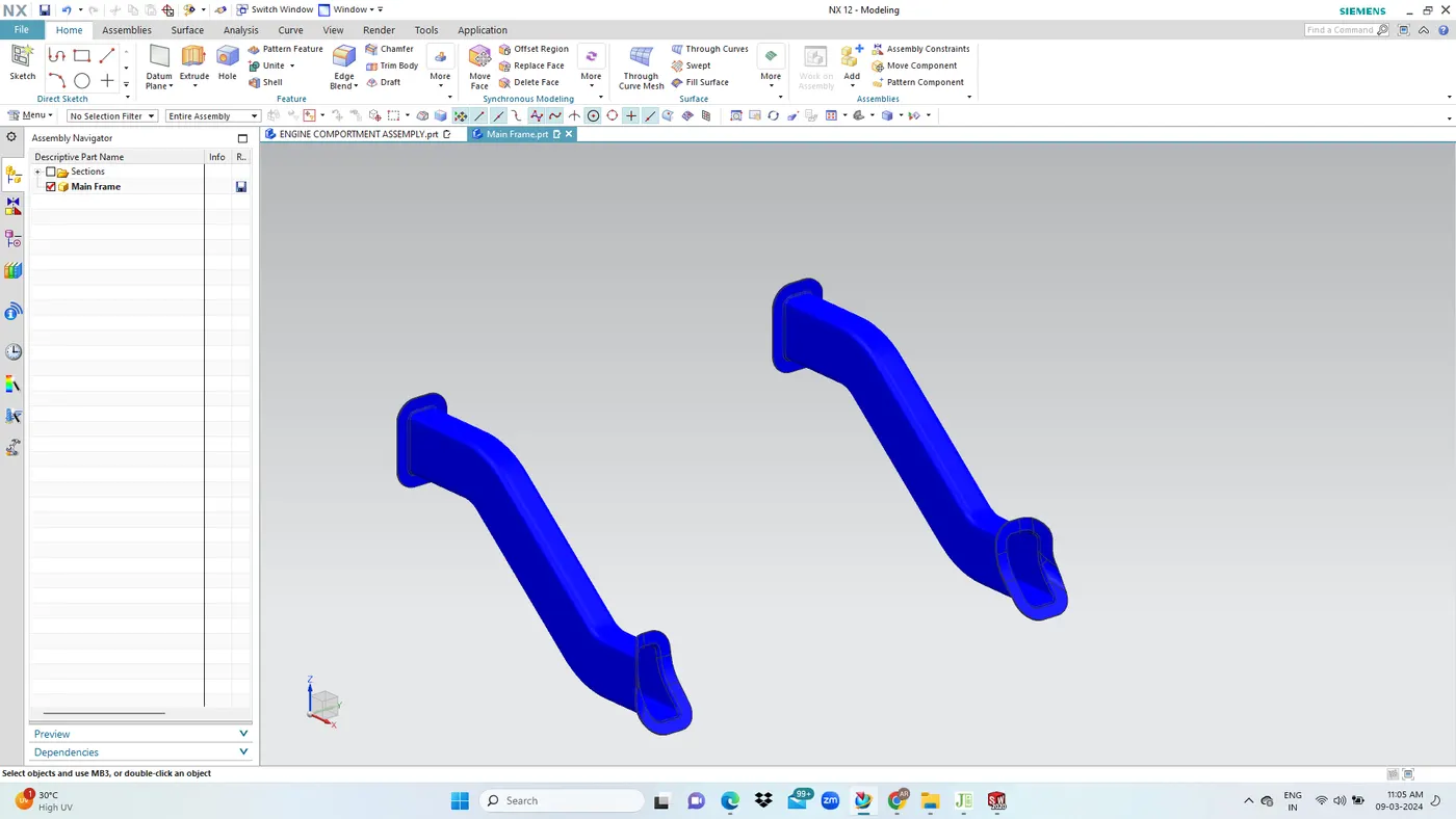
- The lower frame has a cross section of 120x60 mm and is given athickness of 2.3mm. This member has to be made stronger as it holds parts such as bumber mount, suspension mount and dashboard side mount.
- There is a right hand side and a left hand side member.
- Steel structural members with support flanges are used with weldings for joining.
Main Frame Joining Method:
- The main frame is either bolted or welded with the front bumber frame member.
- There should be consideration for enough flat face for the locating holes.
FRONT BUMPER STRUCTURE:
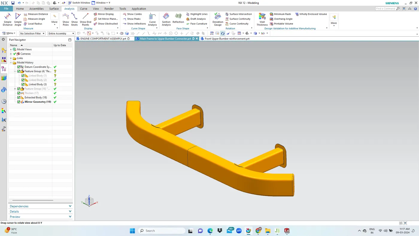
- Front bumper structure forms the first point of contact in the chassis structure in case of a frontal impact.
- The frontal bumper structure plays a huge role in taking the crash load. This structure dissipates and crumples.
- It forms a part of the crumpling zone to absorb the energy during frontal impact.
- Thick square channels with 2.2mm thickness 90x60 section is used for the front bumper structure.
Joining Method:
- The front bumper member will either be welded or bolted with the main frame member at the flange region.
LOWER FRAME SIDE MEMBER:
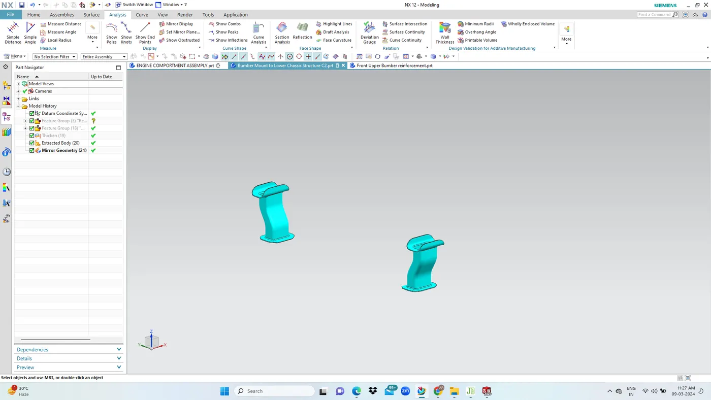
- This additional tubing with flanges is used on both side to join the lower frame member with the main frame.
- It has a cross section of 40x40mm with a thickness of 2.3mm.
- The crash impact forc dissipation will be carried out in this area wherein the welded joint breaks and the force of the impact gets dissipated.
Lower Member Joining:
- The lower frame gets joined with the main frame with an additional member which gets welded on either side.
- This additional member has a square cross section.
FRONT BUMPER AND LOWER CHASSIS MEMBER CONNECTOR:
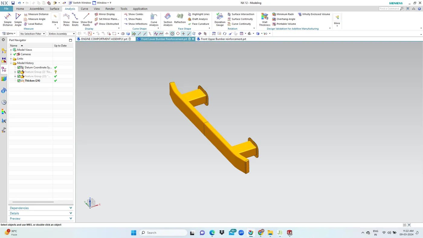
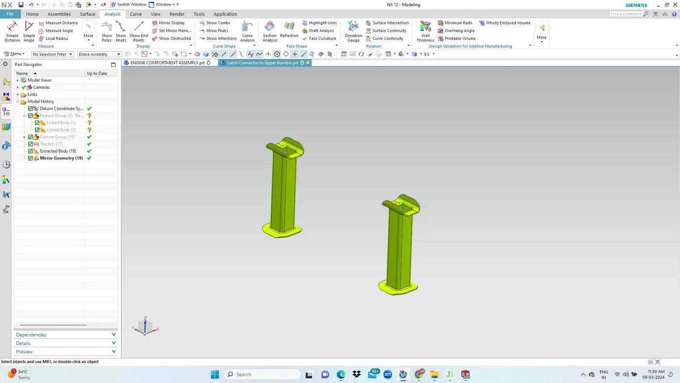
- The connector member is a tubular structure with rectangular cross section with welding flanges.
- This holds the upper bumber structure and lower chassis member in place along with additional support during crash.
- On the front side, the lower frame member is joined with the main frame bumper member with square tubing that has flanges(connectors) for welding.
ENGINE COMPARTMENT LOWER FRAME MEMBER:
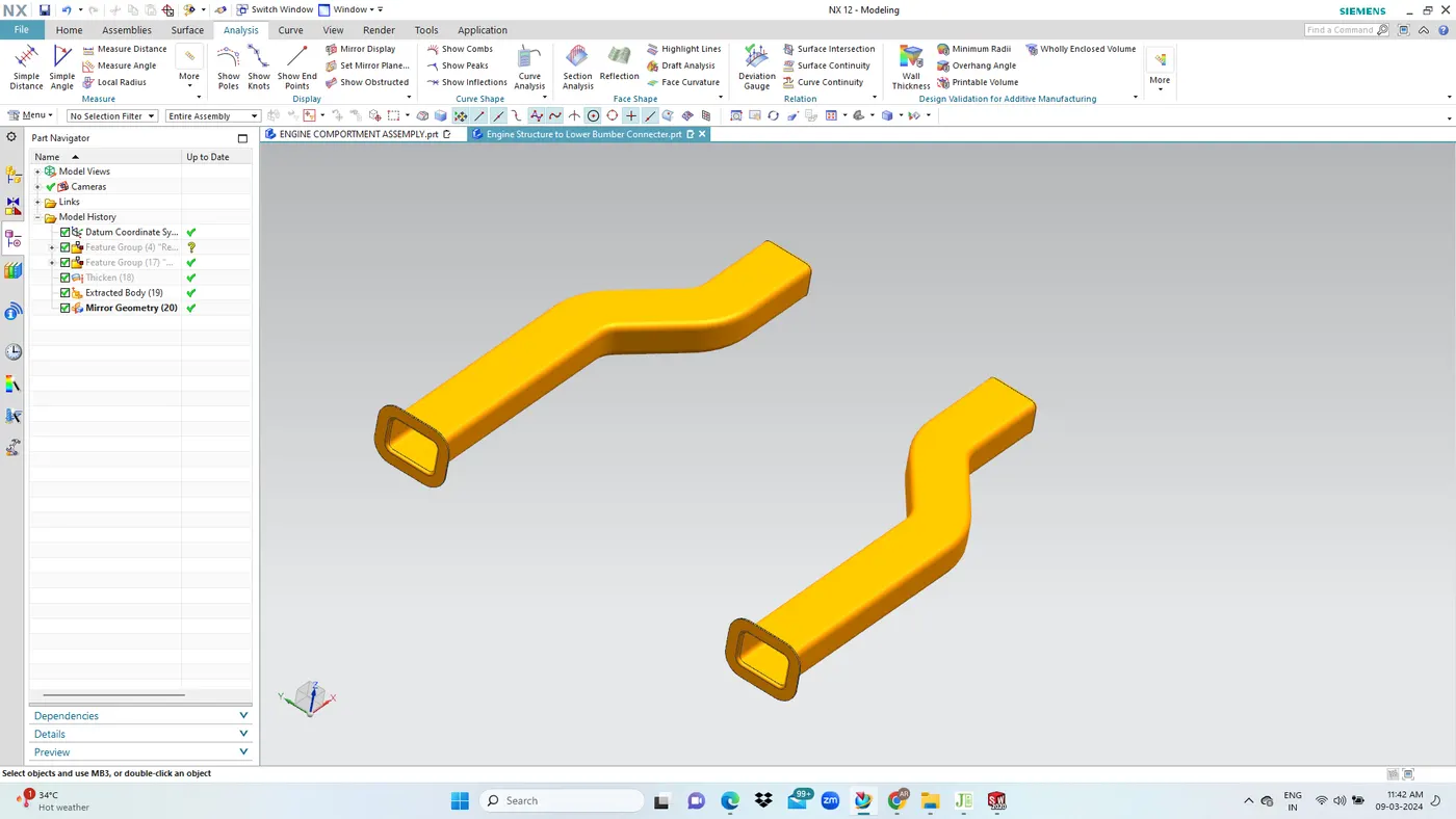
- Engine compart lower panel is a 2 part structure that thas the main lower part and the lower bumper mounting member.
- This portion is to hold the engine from the lower side and to have the mounting points for the suspensions system A arms. wishbones etc.
- Additionally it provide bumper support as well.
ENGINE COMPARTMENT FENDER SIDE MEMBER:
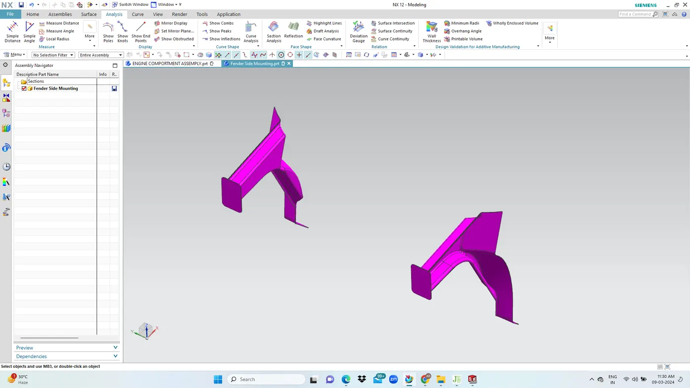
- Engine compartment fender side member is the part that supports the fender member in the drip area region.
- It is joined to the latch member with an elongated turbing in-between.
- On the rear side, the fender mounting is joined with the body side inner along with the engine compartment to form a layer for side impact.
Joining Method:
- The fender side member gets joined with the body side inner and dashboard panel on the rear side which are welded together in a sandwiched manner.
- Three parts are joinded together with the fender portion coming in between, to provide better strength and support.
SUSPENSION STRUCTURE MOUNTING PANEL:
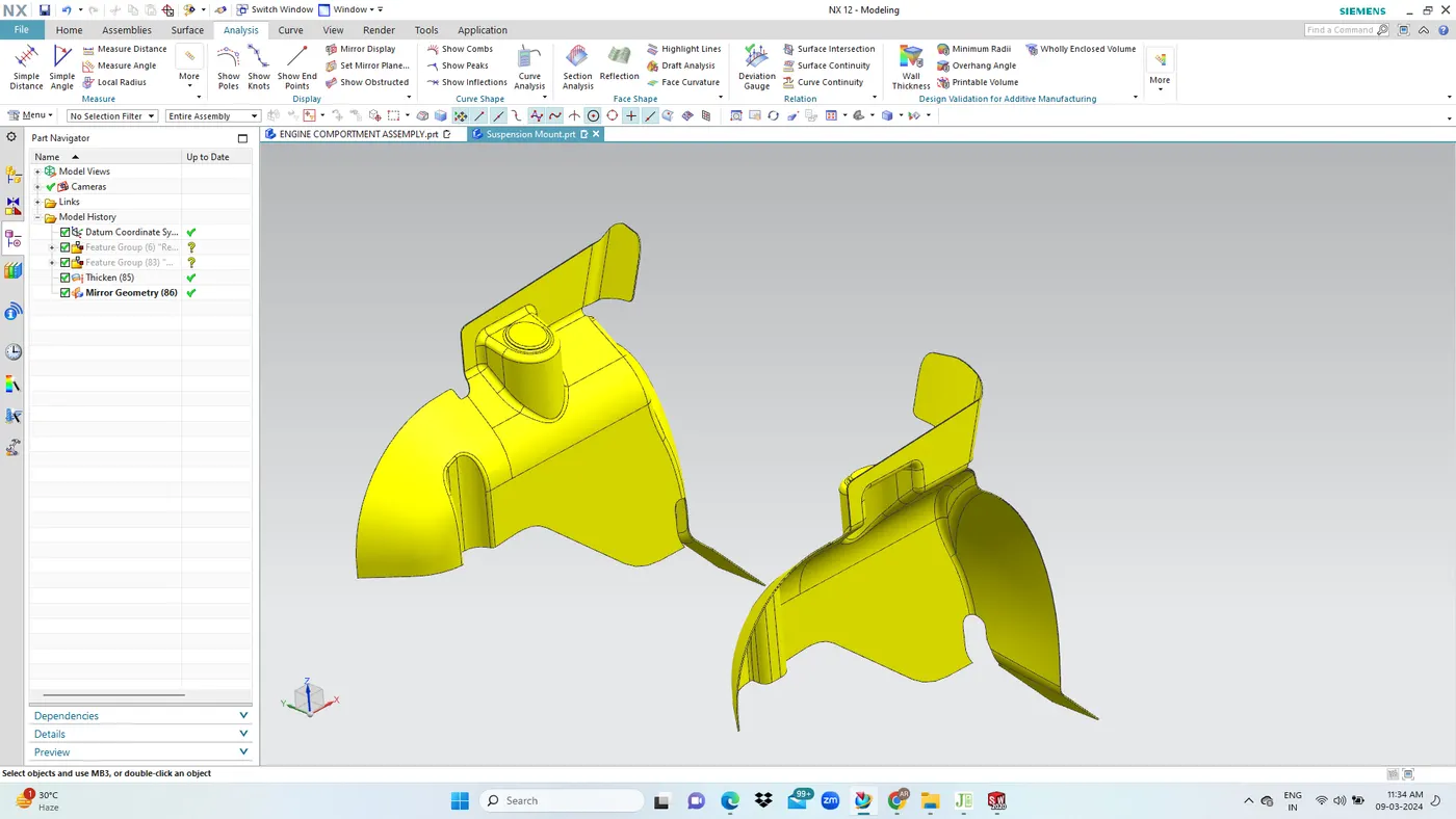
- Suspension structure mounting panel joins the fender side member and the main chassis panel.
- It has a thickness in the range of 2mm to 2.3mm.
- This sheet metal part is deep drawn in the case of steel and for a lightweightapproach it may be casted with aluminium meterial which enables variable thickness and weight reduction.
Joining Method:
- At the top, the suspension structure mount gets welded with the fender side member.
- The fender side member and the suspension structure mounting panel will be welded together to form a strong structure that can take up loads due to side crash and frontal offset crash.
- At the lower end of thr suspension mount, the main chassis frame is welded and joined together will the help of L clamps to from a continuous structure.
- Accurate welding has to be performed to have proper closure for the enginr compartment bay area.
L CLAMP :
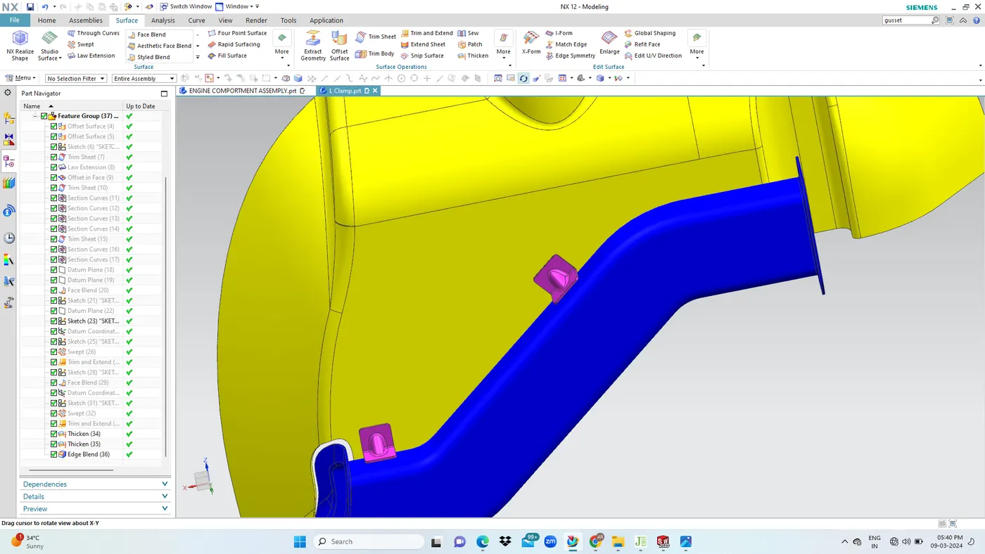
- The L clamp is also called as a metal tab with a 90degree bend.
- To increase the strength of the structure, we provide the L bracket with ribs.
FRONT LATCH MEMBER:
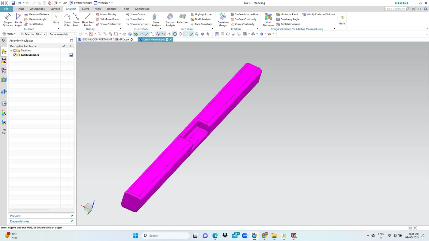
- Front latch bracket attachment is a hollow tube with square section that is designed to have the bracket for the hood latch mechanism.
LATCH SUPPORT CONNECTOR:
ENGINE MOUNTING PLATE:
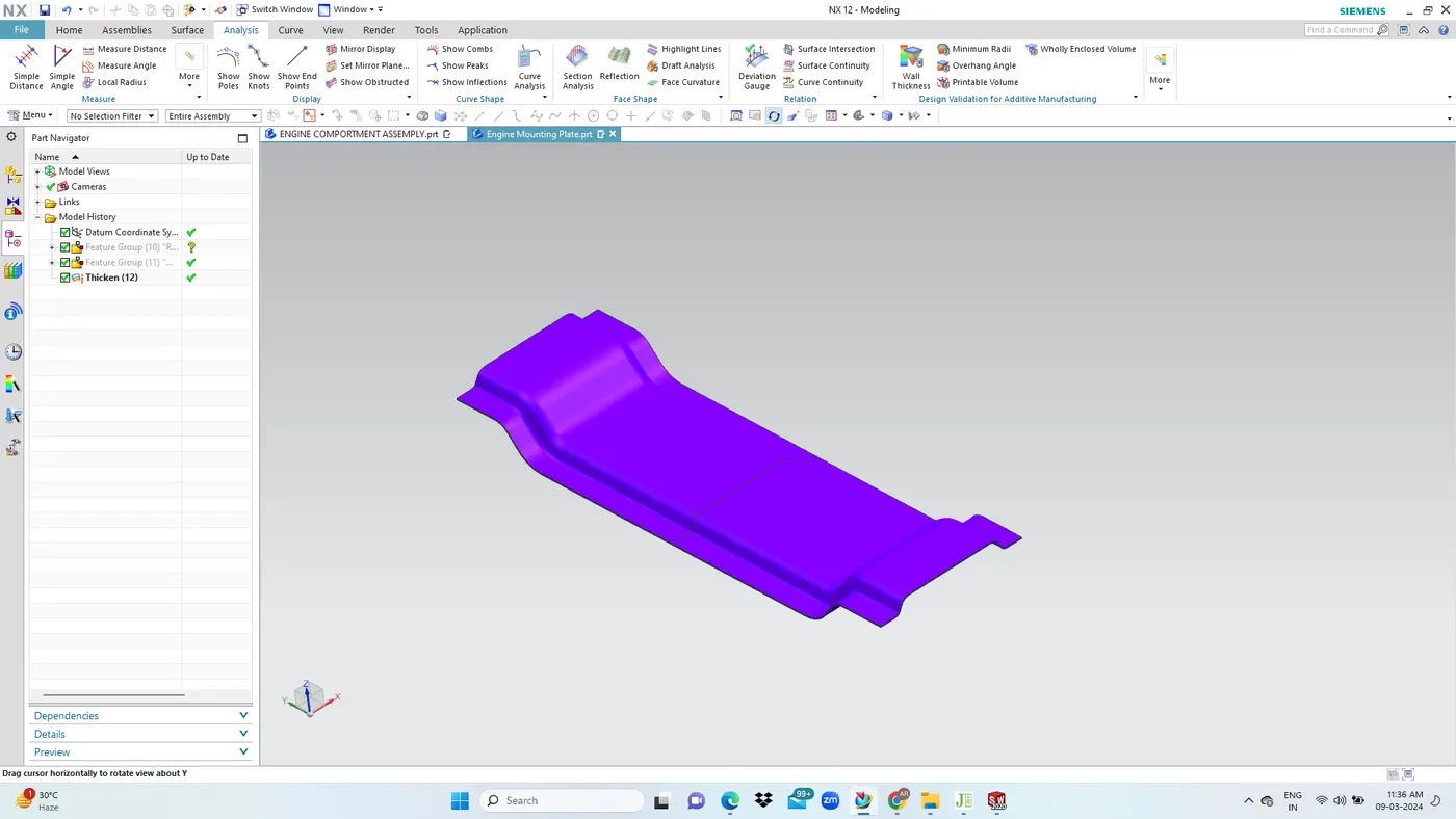
- Engine mounting plate is a thick metal structure that is resistant to abrasion.
- It is mounted on the lower chassis panel and is welded or bolted to the chassis dtructure.
Functional Requirment:
- The plate is abrasion resistant and protects the vehicle from road undulations
- It holds the engine in place at the bottom end.
- It protects the engine from dust, dirt and debris.
LATCH MEMBER TO FENDER MOUNT CONNECTOR:
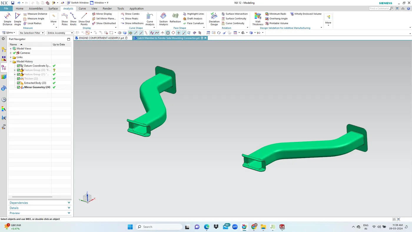
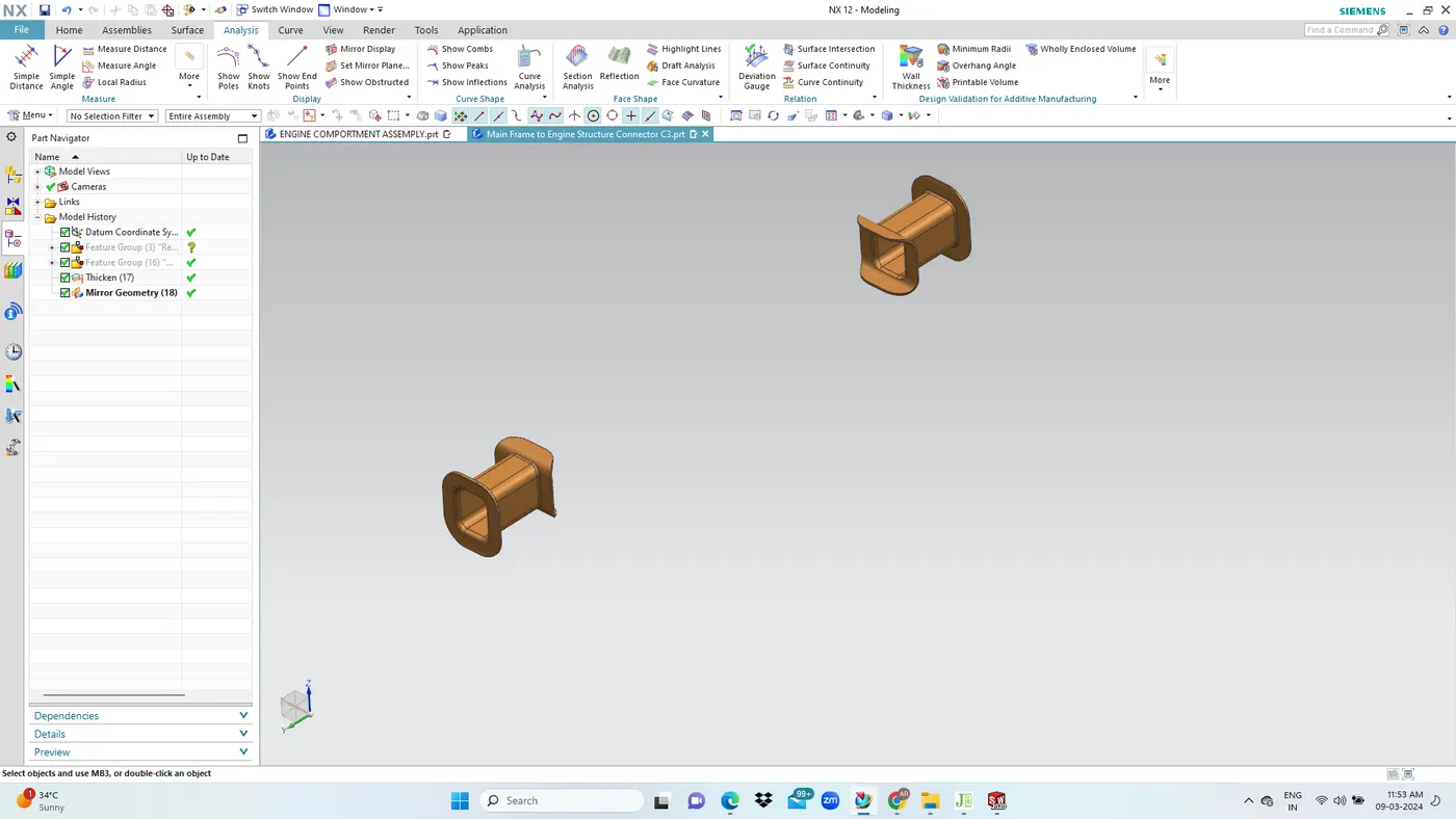
- This member is a strong tubing that connect the fender mount on the side and latch mount member on the front on the engine compartment.
JOINING METHODOLOGY:
- The engine mounting plate is placed over the lower chassis member.
- It is welded on to the same for proper fixation and to take up engine load.
FUNCTIONAL REQIRMENTS:
- This connector maintain the gap between the fender and front latch member and holds the parts in their respective places.
- This member forms mounting points for car lighting and radiator components.
JOINING METHODOLOGY:
- On the front end the connector is welded to the latch member with weld flanges, and on the fender mounting panel, a metal plate is provided to which the flange of the connector gets mounted.
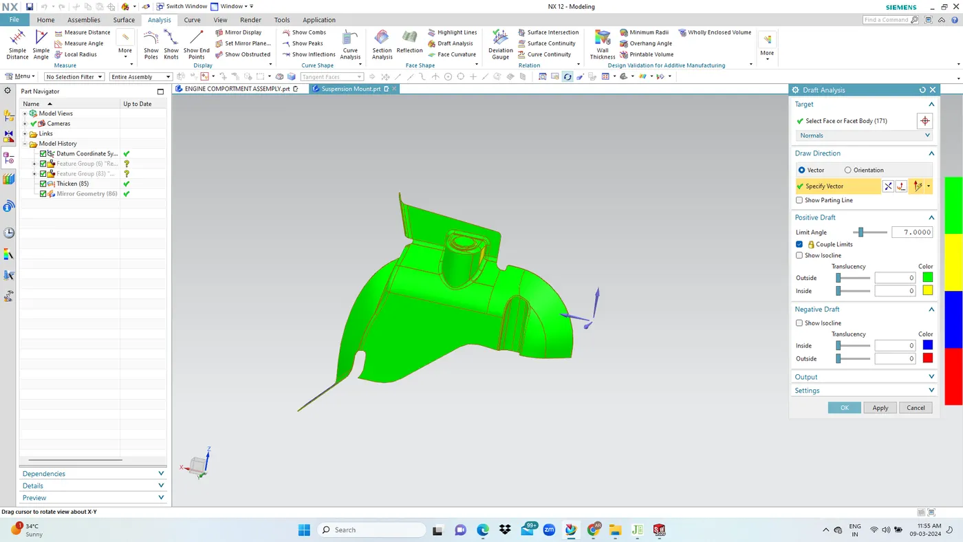
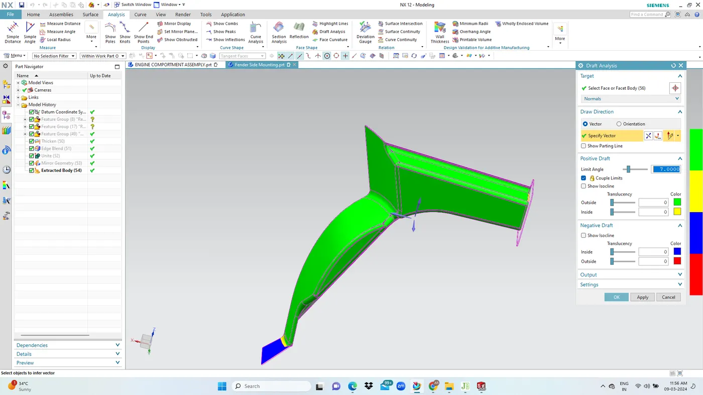
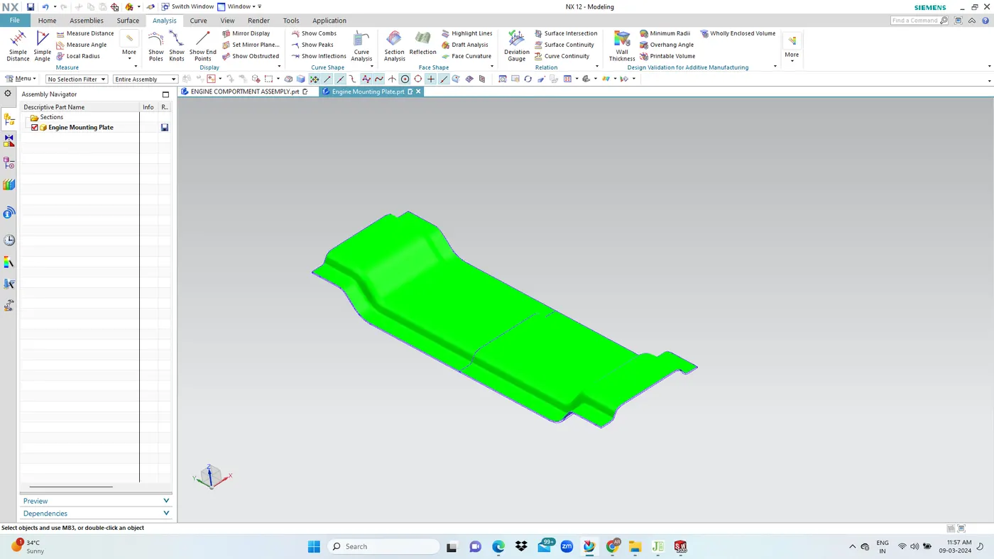
DRAFT ANALYSIS:We are apply the minimum positive draft angle 7 degree of below the components.
SUSPENSION MOUNT:
FENDER SIDE MOUNT:
ENGINE MOUNTING PLATE:
CONCLUSION: The design and development of automotive Engine Compartment assemply was completed with required reinforcement and desigh consideration by using NX CAD is done.
NOTE:
https://drive.google.com/file/d/1LW3BZXxEi47KNMt0LrcDZrAkX0gPPLrS/view?usp=sharing