Drafting of various geometries using Chamfer, Fillet tool in AutoCad
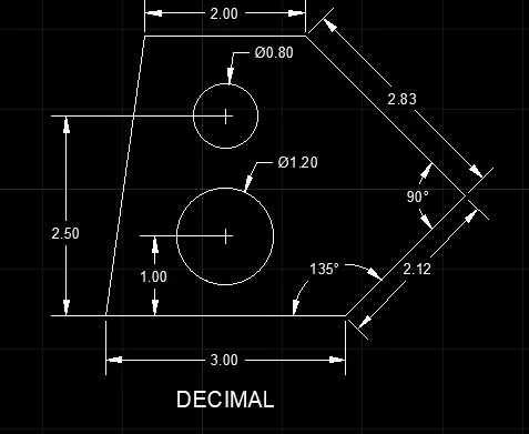
Q.1] Aim and Introduction:- Decimal exercise will explain the step by step procedure to create geomentry as shown in
the following figure using the Polar coordinate system:-
Procedure:-
1. Open AutoCAD and open a new drawing
2. Type UN and press enter. Set the necessary limits and unit as DECIMAL.
3. Type L at command window and press enter
4. Specify first point: Take any point as starting point.
5. Specify next point: Specify the next point at @3<0 and press enter
6. Specify next point: Specify the next point at @2.12<45 and press enter
7. Specify next point: Specify the next point at @2.83<135 and press enter
8. Type C and press enter to Create Circle.
9. Specify next point or close: Select the close option and save the drawing with proper file name.
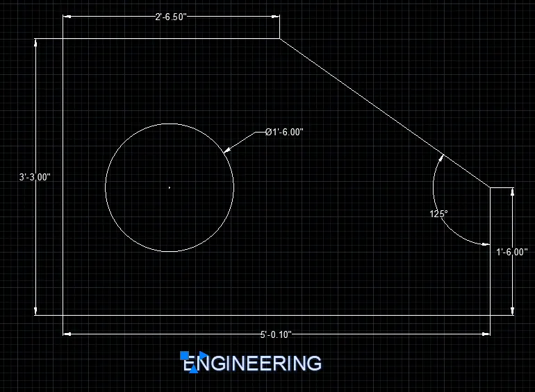
Q.2] Aim and Introduction:- Engineering exercise will explain the step by step procedure to create geomentry as shown
in the following figure using the Polar coordinate system:-
Procedure:-
1. Open AutoCAD and open a new drawing
2. Type UN and press enter. Set the necessary limits and unit as Engineering.
3. Type L at command window and press enter
4. Specify first point: Take any point as starting point.
5. Specify next point: Specify the next point at @5'10"<0 and press enter
6. Specify next point: Specify the next point at @1'6"<90 and press enter
7. Specify next point: From starting point Specify the next point at @3'3"<90 and press enter
8. Specify next point: Specify the next point at @2'6.5"<90 and press enter
9. Type C and press enter to Create Circle.
10. Specify next point or close: Select the close option and save the drawing with proper file name.
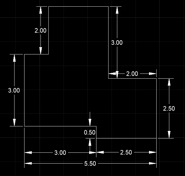
Q.3] Aim and Introduction:- Exercise will explain the step by step procedure to create geomentry as shown in
the following figure using the Polar coordinate system:-
Procedure:-
1. Open AutoCAD and open a new drawing
2. Type UN and press enter. Set the necessary limits and unit as DECIMAL.
3. Type L at command window and press enter
4. Specify first point: Take any point as starting point.
5. Specify next point: Specify the next point at @3<0 and press enter
6. Specify next point: Specify the next point at @0.5<270 and press enter
7. Specify next point: From starting point Specify the next point at @2.5<0 and press enter
8. Specify next point: Specify the next point at @2.5<90and press enter
9. Specify next point: Specify the next point at @2<180 and press enter
10. Specify next point: Specify the next point at @3<90and press enter
11. Specify next point: Specify the next point at @2.5<180 and press enter
12. Specify next point: Specify the next point at @2<270 and press enter
13. Specify next point: Specify the next point at @1<180 and press enter
14. Specify next point or close: Select the close option and save the drawing with proper file name.
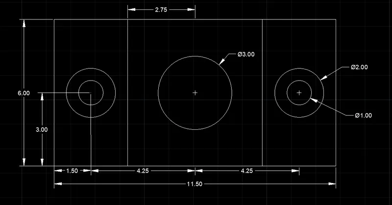
Q.4] Aim and Introduction:- Exercise will explain the step by step procedure to create geomentry as shown in
the following figure using the Polar coordinate system:-
Procedure:-
1) Create a new drawing file with a metric template.
2) Type UN in the command window and press enter. The Drawing Units dialog box will appear.
3) Select the Length Type as Decimals and click ok.
4) Type Z and Type A at command window for Zoom all option.
5) Access REC command and draw the horizontal line of 3.00 length and vertical line of 6.00 length.
6) Specify first point: Take any point on Grid as starting point.
7) Again REC command and draw Rectangle 5.5x6.
8) Type CO and select the 3x9 rectangle Copy it as per given drawing.
9) Type C and press enter to create the circles as per given drawing.
10) Dimensioning and Naming the Drawing by using DIM and T command at command window and press enter.
11) Go to Menu bar and Save the drawing with proper file name. This Complete the Task.
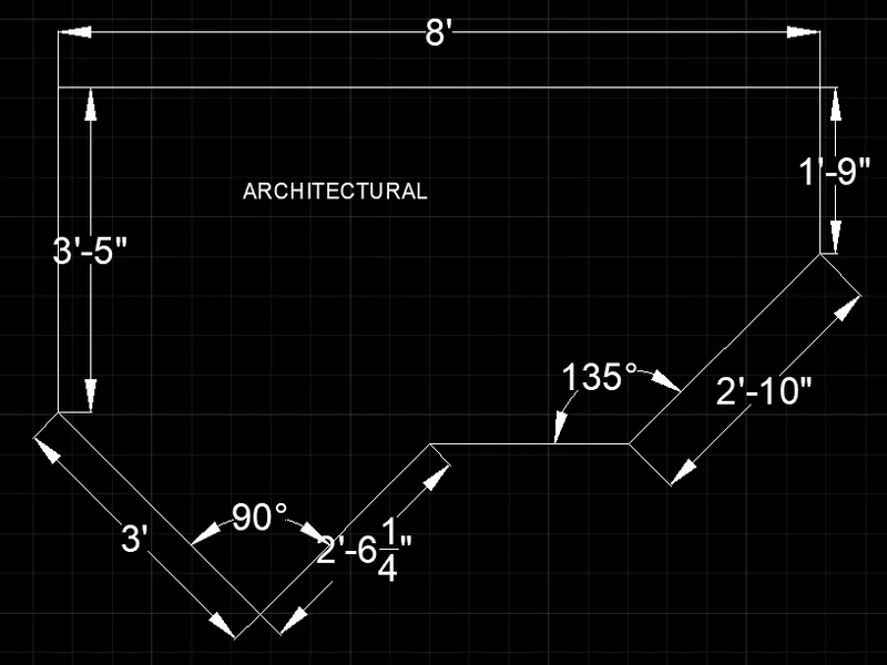
Q.5] Aim and Introduction:- Exercise will explain the step by step procedure to create geomentry as shown in
the following figure using the Polar coordinate system:-
Procedure:-
1) Create a new drawing file with a metric template.
2) Type UN in the command window and press enter. The Drawing Units dialog box will appear.
3) Select the Length Type as ARCHITECTURAL and click ok.
4) Type Z and Type A at command window for Zoom all option.
5) Type L at command window and press enter
6) Specify first point: Take any point as starting point.
7) Specify next point: Specify the next point at @8'<0 and press enter
8) Specify next point: Specify the next point at @1'9"<270 and press enter
9) Specify next point: From starting point Specify the next point at @3'5"<270 and press enter
10) Specify next point: Specify the next point at @3'<315 and press enter
11) Specify next point: Specify the next point at @2'6.25"<45 and press enter
12) Dimensioning and Naming the Drawing by using DIM and T command at command window and press enter.
13) Go to Menu bar and Save the drawing with proper file name. This Complete the Task.
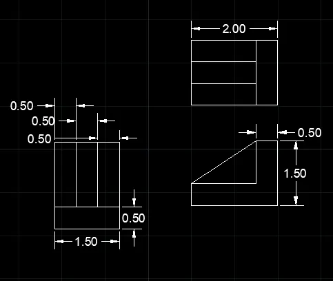
Q.6] Aim and Introduction:- Exercise will explain the step by step procedure to create geomentry as shown in
the following figure using the Polar coordinate system:-
Procedure:-
1) Create a new drawing file with a metric template.
2) Type UN in the command window and press enter. The Drawing Units dialog box will appear.
3) Select the Length Type as Decimals and click ok.
4) Type Z and Type A at command window for Zoom all option.
5) Type L at command window and press enter
6) Specify first point: Take any point as starting point.
7) ON Ortho(press fn+F8) and draw the lines according as per given drawing.
8) Dimensioning and Naming the Drawing by using DIM and T command at command window and press enter.
9) Go to Menu bar and Save the drawing with proper file name. This Complete the Task.
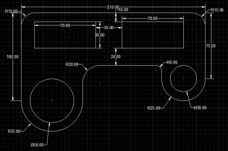
Q.7] Aim and Introduction:- Exercise will explain the step by step procedure to create geomentry as shown in
the following figure using the Polar coordinate system:-
Procedure:-
1) Create a new drawing file with a metric template.
2) Type UN in the command window and press enter. The Drawing Units dialog box will appear.
3) Select the Length Type as Decimal and click ok.
4) Type Z and Type A at command window for Zoom all option.
5) Type L at command window and press enter
6) Specify first point: Take any point as starting point.
7) Specify next point: Specify the next point at @210<0 and press enter
8) Specify next point: Specify the next point at @75<270 and press enter
9) Specify next point: From starting point Specify the next point at @100<270 and press enter
10) Type FILLET and press enter. Create with Radius 15.00, 20.00, 6.00 as shown in given drawing.
11) Go to Home select Arc. select (Start, End,Radius). Create Arc as per given drawing
12) Type REC to create the Rectangle(30x70) at a distance of 20.00 unit away from 100.00 unit horizontally.
13) Type CO and press enter. Select rectangle copy it as shown in drawing.
14) Dimensioning and Naming the Drawing by using DIM and T command at command window and press enter.
15) Go to Menu bar and Save the drawing with proper file name. This Complete the Task.
Q.8] Aim and Introduction:- Exercise will explain the step by step procedure to create geomentry as shown in
the following figure using the Commands:-
Procedure:-
1) Create a new drawing file with a metric template.
2) Type UN in the command window and press enter. The Drawing Units dialog box will appear.
3) Select the Length Type as Decimals and click ok.
4) Type Z and Type A at command window for Zoom all option.
5) Type L at command window and press enter
6) Specify first point: Take any point as starting point.
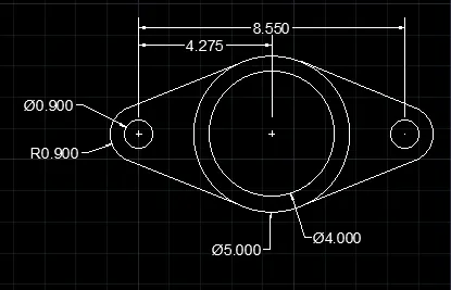
7) Type C press enter to create circles one is 4.00dia and other is 5.00dia.
8) Type C and press enter to create small circles 0.900dia from the centre at a distance of 4.275 unit both side.
9) Choice the Fillet Option as shown in given drawing.
10) Dimensioning and Naming the Drawing by using DIM and T command at command window and press enter.
11) Go to Menu bar and Save the drawing with proper file name. This Complete the Task.
Q.9] Aim and Introduction:- Exercise will explain the step by step procedure to create geomentry as shown in
the following figure using the Commands:-
Procedure:-
1) Create a new drawing file with a metric template.
2) Type UN in the command window and press enter. The Drawing Units dialog box will appear.
3) Select the Length Type as Decimals and click ok.
4) Type Z and Type A at command window for Zoom all option.
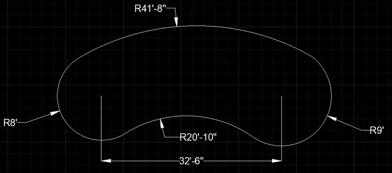
5) Type L at command window and press enter. Specify the next point at @32'6"<0 and press enter
6) Specify first point: Take any point as starting point.
7)Access the Arc Command and create the arc of Radius is 8', 9', 41'8" and 20'10" as shown in given figure.
8) Dimensioning and Naming the Drawing by using DIM and T command at command window and press enter.
9) Go to Menu bar and Save the drawing with proper file name. This Complete the Task.
Q.10] Aim and Introduction:- Exercise will explain the step by step procedure to create geomentry as shown in
the following figure using the Commands:-
Procedure:-
1) Create a new drawing file with a metric template.
2) Type UN in the command window and press enter. The Drawing Units dialog box will appear.
3) Select the Length Type as Decimals and click ok.
4) Type Z and Type A at command window for Zoom all option.
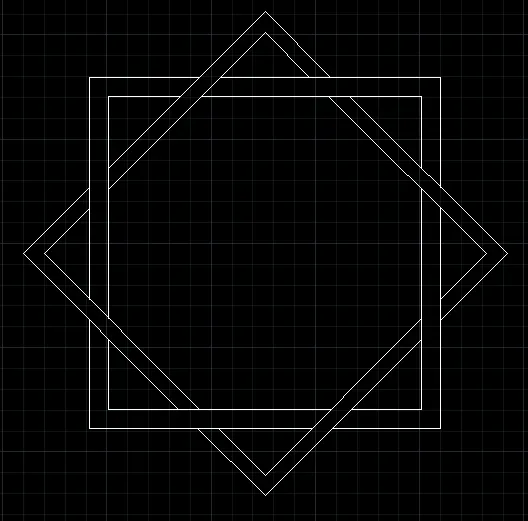
5) Type REC and press enter. To create the Rectangle.
6) Specify first point: Take any point as starting point.
7) Access the OFFSET command and create the offset of rectangle.
8) Type REC and press enter. Select Rotation option at an angle of 45 degree. Then create same size of rectangle.
9) Access the OFFSET command and create the offset of tilt rectangle.
10) Go to Menu bar and Save the drawing with proper file name. This Complete the Task.
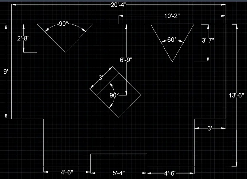
Q.11] Aim and Introduction:- Exercise will explain the step by step procedure to create geomentry as shown
in the following figure using the Polar coordinate system:-
Procedure:-
1. Open AutoCAD and open a new drawing
2. Type UN and press enter. Set the necessary limits and unit as Engineering.
3. Type L at command window and press enter
4. Specify first point: Take any point as starting point.
5. Specify next point: Specify the next point at @9'<270 and press enter
6. Specify next point: Specify the next point at @3'<180 and press enter
7. Specify next point: Specify the next point at @4'6"<270 and press enter
8. Specify next point: Specify the next point at @4'6"<180 and press enter
9. Specify next point: Specify the next point at @1'2"<90 and press enter
10. Specify next point: Specify the next point at @5'4"<180 and press enter
11. Specify next point: Specify the next point at @1'2"<270 and press enter
12. Specify next point: Specify the next point at @4'6"<180 and press enter
13. Specify next point: Specify next point: Specify the next point at @4'6"<90 and press enter
14. Specify next point: Specify the next point at @3'<180 and press enter
15.Specify next point: Specify the next point at @9'<90 and press enter
16. Specify next point: Specify the next point at @10'2"<0 and press enter
17. Specify next point: Specify the next point at @10'2"<0 and press enter
18. Type REC to create the 3'x3' rectangle at a distance of 6'9" unit.
19. Dimensioning and Naming the Drawing by using DIM and T command at command window and press enter.
20. Go to Menu bar and Save the drawing with proper file name. This Complete the Task.