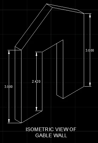
Creating a Floor plan, Footing detail and Isometric view using AutoCad
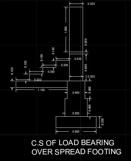
Q.1] Aim and Introduction:- The tutorial will explain step by step procedure to C.S of Load Bearing wall Over Spread
Footing.
Procedure:-
1) Create a new drawing file with a metric template.
2) Type UN in the command window and press enter. The Drawing Units dialog box will appear.
3) Select the Length Type as Decimals and click ok.
4) Type Z and Type A at command window for Zoom all option.
5) Turn ON the Orthomode(Press fn+F8) for curser move Vertically and Horizontally.
6) Type L(Line) at command prompt and press enter.
7) Access line command and draw the horizontal line of 0.900 length and vertical line of 0.250 length.
8) Specify first point: type (2,2) at command prompt and press enter(as starting point)
9) Specify next point: Specify the next point at @0,0.250 and press enter
10) Specify next point: Specify the next point at @0.2,0 and press enter
11) Specify next point: Specify the next point at @0,0.40 and press enter
12) Specify next point: Specify the next point at @0.05,0 and press enter
13) Specify next point: Specify the next point at @0,0.40 and press enter
14) Specify next point: Specify the next point at @0,0.050 and press enter
15) Specify next point: Specify the next point at @0,0.60 and press enter
16) Specify next point: Specify the next point at @0,0.050 and press enter
17) Specify next point: Specify the next point at @0,1 and press enter
18) Type MI(Mirror) and press enter and select the all drawing Specify the corner and mirror it
19) After that Type M(move) and press enter then specify corner point and the mirror object at @0.30,0 and press enter.
20) Type L in command prompt and press enter and Join all Line as per given Drawing.
21) Type L in command prompt and press enter and specify the first point at the height of 0.80 length vertically.
22) Specify next point: Specify the next point at @-1.15,0 and press enter
23) Specify next point: Specify the next point at @0,0.15 and press enter
24) Specify next point: Specify the next point at @0.3,0 and press enter
25) Select the line 0.15 and 0.3. Type CO(Copy) and enter. Select the first corner point. Type A(Array) at command
window and Enter the Number of items to array is 4. Specify the second point and press enter.
26) Dimensioning and Naming the Drawing by using DIM and T command at command window and press enter.
27) Go to Menu bar and Save the drawing with proper file name. This Complete the Task.
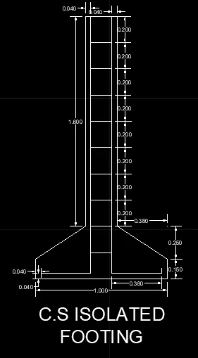
Q.2] Aim and Introduction:- The tutorial will explain step by step procedure to C.S of Isolated Footing by using commands
and Relative Coordinate System Method.
Procedure:-
1) Create a new drawing file with a metric template.
2) Type UN in the command window and press enter. The Drawing Units dialog box will appear.
3) Select the Length Type as Decimals and click ok.
4) Type Z and Type A at command window for Zoom all option.
5) Type L(Line) at command prompt and press enter.
6) Specify the first point at anywhere to start the drawing.
7) Specify next point: Specify the next point at @1,0 and press enter
8) Specify next point: Specify the next point at @0,0.150 and press enter
9) Specify next point: Specify the next point at @0,0.250 and press enter
10) Specify next point: Specify the next point at @-0.38,0 and press enter
11) Specify next point: Specify the next point at @0,1.60 and press enter
12) Specify next point: Specify the next point at @-0.24,0 and press enter
13) Specify next point: Specify the next point at @0,-1.60 and press enter
14) Specify next point: Specify the next point at @-0.380,0 and press enter
15) Specify next point: Select the close option or Specify the next point at @0,-0.250 and press enter
16) Type O(Offset) at commmand prompt and press double enter. Type T at command window and press enter. Select
the vertical line having length of 1.60 and take offset Horizontally at the side as per given drawing of 0.04 length.
17) Type L at command window and enter. Make a block 0.24*0.20 seperatly.
18) Type CO at command window and enter. Specify the first corner of block. Copy the block 8 times as per in drawing.
19) Join all Line as shown in given figure.
20) Dimensioning and Naming the Drawing by using DIM and T command at command window and press enter.
21) Go to Menu bar and Save the drawing with proper file name. This Complete the Task.
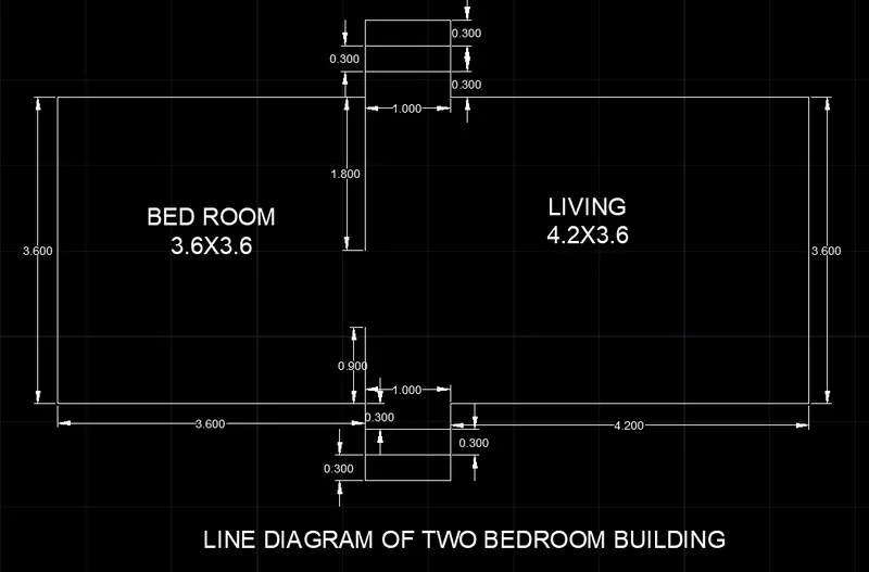
Q.3] Aim and Introduction:- The tutorial will explain step by step procedure to Line Diagram of Two Bedroom Building by
using commands and Relative Coordinate System Method.
Procedure:-
1) Create a new drawing file with a metric template.
2) Type UN in the command window and press enter. The Drawing Units dialog box will appear.
3) Select the Length Type as Decimals and click ok.
4) Type Z and Type A at command window for Zoom all option.
5) Turn ON the Orthomode(Press fn+F8) for curser move Vertically and Horizontally.
6) Type L(Line) at command prompt and press enter.
7) Specify the first point at anywhere to start the drawing.
8) Specify next point: Specify the next point at @3.6,0 and press enter
9) Specify next point: Specify the next point at @0,-0.3 and press enter
10) Specify next point: Specify the next point at @0,-0.3 and press enter
11) Specify next point: Specify the next point at @0,-0.3 and press enter
12) Specify next point: Specify the next point at @1,0 and press enter
13) Specify next point: Specify the next point at @0,0.3 and press enter
14) Specify next point: Specify the next point at @0,0.3 and press enter
15) Specify next point: Specify the next point at @0,0.3 and press enter
16) Specify next point: Specify the next point at @4.2,0 and press enter
17) Specify next point: Specify the next point at @0,3.6 and press enter
18) Specify next point: Specify the next point at @-4.20,0 and press enter
19) Specify next point: Specify the next point at @0,0.3 and press enter
20) Specify next point: Specify the next point at @0,0.3 and press enter
21) Specify next point: Specify the next point at @0,0.3 and press enter
22) Specify next point: Specify the next point at @-1,0 and press enter
23) Specify next point: Specify the next point at @0,-0.3 and press enter
24) Specify next point: Specify the next point at @0,-0.3 and press enter
25) Specify next point: Specify the next point at @0,-0.3 and press enter
26) Specify next point: Specify the next point at @-3.6,0 and press enter
27) Specify next point: Select the close option or Specify the next point at @0,-3.60 and press enter
28) Join further Lines as shown in given figure.
29) Dimensioning and Naming the Drawing by using DIM and T command at command window and press enter.
30) Go to Menu bar and Save the drawing with proper file name. This Complete the Task.
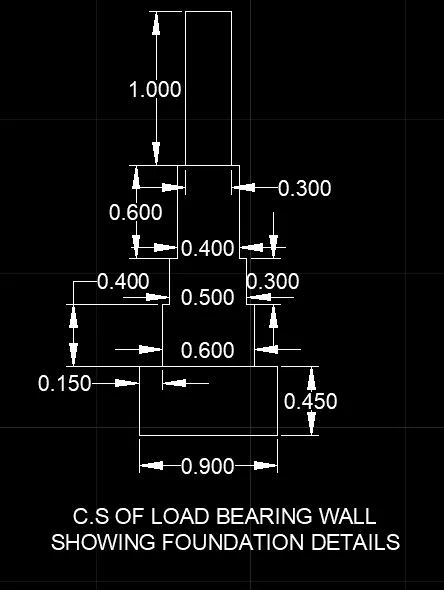
Q.4] Aim and Introduction:- The tutorial will explain step by step procedure to C.S of Load Bearing Wall Showing
Foundation Details by using commands and Relative Coordinate System Method.
Procedure:-
1) Create a new drawing file with a metric template.
2) Type UN in the command window and press enter. The Drawing Units dialog box will appear.
3) Select the Length Type as Decimals and click ok.
4) Type Z and Type A at command window for Zoom all option.
5) Turn ON the Orthomode(Press fn+F8) for curser move Vertically and Horizontally.
6) Type L(Line) at command prompt and press enter.
7) Specify the first point at anywhere to start the drawing.
8) Specify next point: Specify the next point at @0.9,0 and press enter
9) Specify next point: Specify the next point at @0,0.45 and press enter
10) Specify next point: Specify the next point at @-0.15,0 and press enter
11) Specify next point: Specify the next point at @0,0.4 and press enter
12) Specify next point: Specify the next point at @-0.05,0 and press enter
13) Specify next point: Specify the next point at @0,0.3 and press enter
14) Specify next point: Specify the next point at @-0.05,0 and press enter
15) Specify next point: Specify the next point at @0,0.6 and press enter
16) Specify next point: Specify the next point at @-0.05,0 and press enter
17) Specify next point: Specify the next point at @0,1 and press enter
18) Specify next point: Specify the next point at @-0.3,0 and press enter
11)Specify next point: Specify the next point at @0,-1 and press enter
12) Specify next point: Specify the next point at @-0.05,0 and press enter
13) Specify next point: Specify the next point at @0,-0.6 and press enter
14) Specify next point: Specify the next point at @-0.05,0 and press enter
15) Specify next point: Specify the next point at @0,-0.3 and press enter
16) Specify next point: Specify the next point at @-0.05,0 and press enter
17) Specify next point: Specify the next point at @0,-0.4 and press enter
18) Specify next point: Specify the next point at @-0.15,0 and press enter
19) Specify next point: Select the close option or Specify the next point at @0,-0.45 and press enter
20) Join further Lines as shown in given figure.
21) Dimensioning and Naming the Drawing by using DIM and T command at command window and press enter.
22) Go to Menu bar and Save the drawing with proper file name. This Complete the Task.
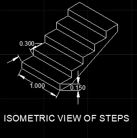
Q.5] Aim and Introduction:- The tutorial will explain step by step procedure to Isometric View of Steps by using
commands and Coordinate System Method.
Procedure:-
1) Create a new drawing file with a metric template.
2) Type UN in the command window and press enter. The Drawing Units dialog box will appear.
3) Select the Length Type as Decimals and click ok.
4) Type Z and Type A at command window for Zoom all option.
5) Turn ON the Orthomode(Press fn+F8) for curser move Vertically and Horizontally.
6) Type L(Line) at command prompt and press enter.
7) Specify the first point at anywhere to start the drawing.
8) Turn ON the Isometric Drafting(Press fn+F5).
9) Select the Isoplane Right.
10) Specify next point: Specify the next point at @0,0.15 and press enter
11) Cursor move in Z-axis length of 0.3. Cursor move upward with 0.15 length.
12) Repeat the method upto 5 Steps.
13) Select Isoplane left.
14) Type CO and enter then select object. Copy the object in X-axis at the length of 1.0.
15) Join further Lines to form Steps as shown in given figure.
16) Dimensioning and Naming the Drawing by using DIM and T command at command window and press enter.
17) Go to Menu bar and Save the drawing with proper file name. This Complete the Task.
Q.6] Aim and Introduction:- The tutorial will explain step by step procedure to Isometric View of Steps by using
commands and Coordinate System Method.
Procedure:-
1) Create a new drawing file with a metric template.
2) Type UN in the command window and press enter. The Drawing Units dialog box will appear.
3) Select the Length Type as Decimals and click ok.
4) Type Z and Type A at command window for Zoom all option.
5) Turn ON the Orthomode(Press fn+F8) for curser move Vertically and Horizontally.
6) Type L(Line) at command prompt and press enter.
7) Specify the first point at anywhere to start the drawing.
8) Turn ON the Isometric Drafting(Press fn+F5).
9) Select the Isoplane Right.
10) Specify next point: Specify the next point at @1,0 and press enter
11) Move Cursor up and give length 2.42 unit. Move cursor right upto 1 unit then down upto 2.42 unit. Move cursor up
upto 3.00 unit.
12) Join further Lines to form Gable wall as shown in given figure.
13) Dimensioning and Naming the Drawing by using DIM and T command at command window and press enter.
14) Go to Menu bar and Save the drawing with proper file name. This Complete the Task.