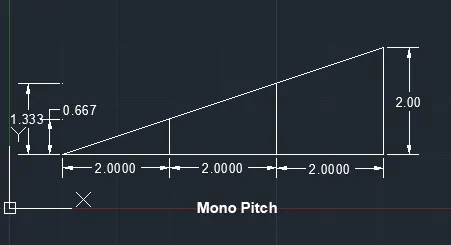
Creation of geometries by Coordinate system methods using AutoCad
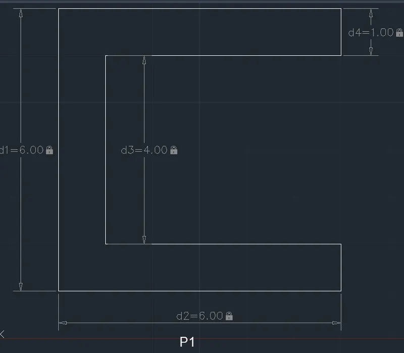
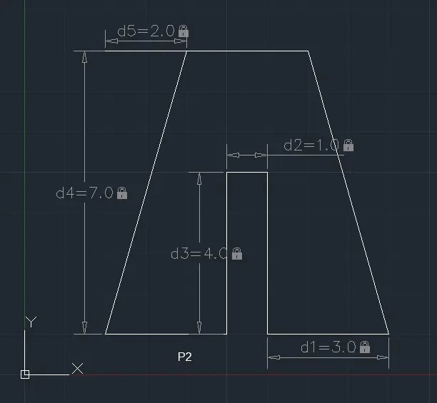
Q.1] Aim and Introduction:- P1 and P2 exercise will explain the step by step procedure to create geomentry as shown in
the following figure using the Relative rectangular coordinate system:-
Procedure:-
For P1:
1. Open AutoCAD and open a new drawing
2. Set the necessary limits and units
3. Type L at command window and press enter
4. Specify first point: type (2,1) at command prompt and press enter (as starting point)
5. Specify next point: Specify the next point in relative method like @6,0 and press enter
6. Specify next point: Specify the next point at @0,1 and press enter
7. Specify next point: Specify the next point at @-5,0 and press enter
8. Specify next point: Specify the next point at @0,4 and press enter
9. Specify next point: Specify the next point at @5,0 and press enter
10. Specify next point: Specify the next point at @0,1 and press enter
11. Specify next point: Specify the next point at @-6,0 and press enter
12. Specify next point or close: Select the close option or Specify the next point at @0,-6 and press enter key and save
the drawing with proper file name.
For P2:
1. Open AutoCAD and open a new drawing
2. Set the necessary limits and units
3. Type L at command window and press enter
4. Specify first point: type (2,1) at command prompt and press enter (as starting point)
5. Specify next point: Specify the next point in relative method like @3,0 and press enter
6. Specify next point: Specify the next point at @0,4 and press enter
7. Specify next point: Specify the next point at @1,0 and press enter
8. Specify next point: Specify the next point at @0,-4 and press enter
9. Specify next point: Specify the next point at @3,0 and press enter
10. Specify next point: Specify the next point at @7,8and press enter
11. Specify next point: Specify the next point at @-3,0 and press enter
12. Specify next point or close: Select the close option or Specify the next point at @-2,-7 and press enter key and save the
drawing with proper file name.
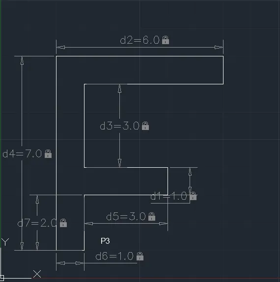
Q.2] Aim and Introduction:- P3 and P4 exercise will explain the step by step procedure to create geomentry as shown in
the following figure using the Relative rectangular coordinate system:-
Procedure:-
For P3:
1. Open AutoCAD and open a new drawing
2. Set the necessary limits and units
3. Type L at command window and press enter
4. Specify first point: type (2,1) at command prompt and press enter (as starting point)
5. Specify next point: Specify the next point in relative method like @1,0 and press enter
6. Specify next point: Specify the next point at @0,2 and press enter
7. Specify next point: Specify the next point at @3,0 and press enter
8. Specify next point: Specify the next point at @0,1 and press enter
9. Specify next point: Specify the next point at @-3,0 and press enter
10. Specify next point: Specify the next point at @0,3 and press enter
11. Specify next point: Specify the next point at @5,0 and press enter
12. Specify next point: Specify the next point at @0,1 and press enter
13. Specify next point: Specify the next point at @-6,0 and press enter
14. Specify next point or close: Select the close option or Specify the next point at @0,-7 and press enter key and save
the drawing with proper file name.
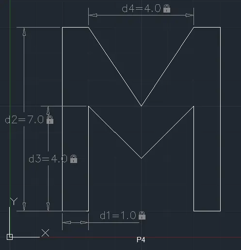
For P4:
1. Open AutoCAD and open a new drawing
2. Set the necessary limits and units
3. Type L at command window and press enter
4. Specify first point: type (2,1) at command prompt and press enter (as starting point)
5. Specify next point: Specify the next point in relative method like @1,0 and press enter
6. Specify next point: Specify the next point at @0,4 and press enter
7. Specify next point: Specify the next point at @2,-2 and press enter
8. Specify next point: Specify the next point at @2,2 and press enter
9. Specify next point: Specify the next point at @0,-4 and press enter
10. Specify next point: Specify the next point at @1,0 and press enter
11. Specify next point: Specify the next point at @0,7 and press enter
12. Specify next point: Specify the next point at @-1,0 and press enter
13. Specify next point: Specify the next point at @-2,-3 and press enter
14. Specify next point: Specify the next point at @-2,3 and press enter
15. Specify next point: Specify the next point at @-1,0 and press enter
16. Specify next point or close: Select the close option or Specify the next point at @0,-7 and press enter key and save
the drawing with proper file name.
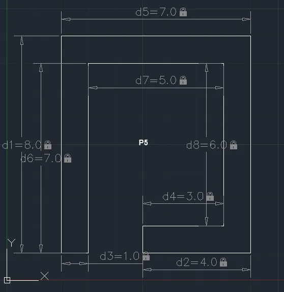
Q.3] Aim and Introduction:- P5, P7 and P8 exercises will explain the step by step procedure to create geomentry as
shown in the following figure using the Polar coordinate system:-
Procedure:-
For P5:
1. Open AutoCAD and open a new drawing
2. Set the necessary limits and units
3. Type L at command window and press enter
4. Specify first point: type (2,1) at command prompt and press enter (as starting point)
5. Specify next point: Specify the next point in relative method like @1<0 and press enter
6. Specify next point: Specify the next point at @7<90 and press enter
7. Specify next point: Specify the next point at @5<0 and press enter
8. Specify next point: Specify the next point at @6<270 and press enter
9. Specify next point: Specify the next point at @3<180and press enter
10. Specify next point: Specify the next point at @1<270 and press enter
11. Specify next point: Specify the next point at @4<0 and press enter
12. Specify next point: Specify the next point at @8<90 and press enter
13. Specify next point: Specify the next point at @7<180and press enter
14. Specify next point or close: Select the close option or Specify the next point at @8<270 and press enter key and save
the drawing with proper file name.
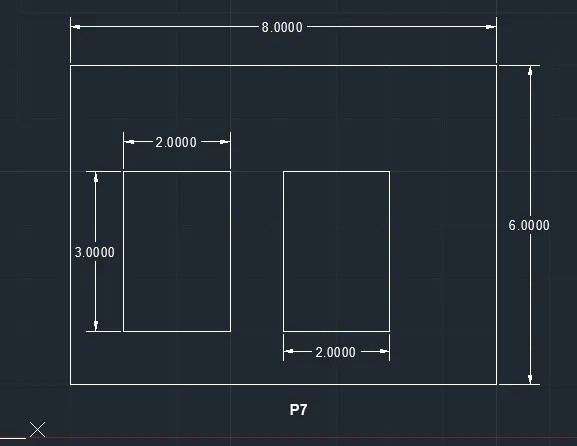
For P7:
1. Open AutoCAD and open a new drawing
2. Set the necessary limits and units
3. Type L at command window and press enter
4. Specify first point: type (2,1) at command prompt and press enter (as starting point)
5. Specify next point: Specify the next point in relative method like @8<0 and press enter
6. Specify next point: Specify the next point at @6<90 and press enter
7. Specify next point: Specify the next point at @8<180 and press enter
8. Specify next point: Specify the next point at @6<270 and press enter
9. Specify next point: type (3,2) at command prompt and press enter
10. Specify next point: Specify the next point at @2<0 and press enter
11. Specify next point: Specify the next point at @3<90 and press enter
12. Specify next point: Specify the next point at @2<180 and press enter
13. Specify next point: Specify the next point at @3<270 and press enter
14. Specify next point: type (6,2) at command prompt and press enter
15. Specify next point: Specify the next point at @2<0 and press enter
16. Specify next point: Specify the next point at @3<90 and press enter
17. Specify next point: Specify the next point at @2<180 and press enter
18. Specify next point or close: Select the close option or Specify the next point at @3<270 and press enter key and save
the drawing with proper file name.
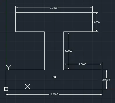
For P8:
1. Open AutoCAD and open a new drawing
2. Set the necessary limits and units
3. Type L at command window and press enter
4. Specify first point: type (0,0) at command prompt and press enter (as starting point)
5. Specify next point: Specify the next point in relative method like @10<0 and press enter
6. Specify next point: Specify the next point at @2<90 and press enter
7. Specify next point: Specify the next point at @4<180 and press enter
8. Specify next point: Specify the next point at @4<90 and press enter
9. Specify next point: Specify the next point at @3<0and press enter
10. Specify next point: Specify the next point at @2<90 and press enter
11. Specify next point: Specify the next point at @8<180 and press enter
12. Specify next point: Specify the next point at @2<270 and press enter
13. Specify next point: Specify the next point at @3<0and press enter
14. Specify next point: Specify the next point at @4<270 and press enter
15. Specify next point: Specify the next point at @4<180 and press enter
16. Specify next point or close: Select the close option or Specify the next point at @2<270 and press enter key and save
the drawing with proper file name.
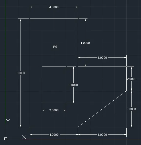
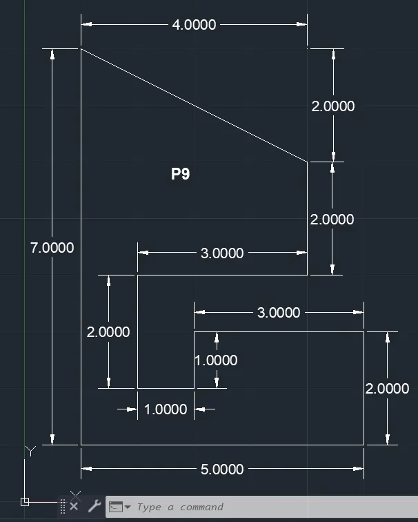
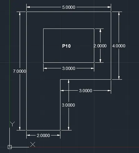
Q.4] Aim and Introduction:- P6,P9 and P10 exercise will explain the step by step procedure to create geomentry as shown
in the following figure using the Relative rectangular coordinate system:-
Procedure:-
For P6:
1. Open AutoCAD and open a new drawing
2. Set the necessary limits and units
3. Type L at command window and press enter
4. Specify first point: type (2,1) at command prompt and press enter (as starting point)
5. Specify next point: Specify the next point in relative method like @4,0 and press enter
6. Specify next point: Specify the next point at @4,3 and press enter
7. Specify next point: Specify the next point at @0,2 and press enter
8. Specify next point: Specify the next point at @-4,0 and press enter
9. Specify next point: Specify the next point at @0,4 and press enter
10. Specify next point: Specify the next point at @-4,0 and press enter
11. Specify next point: Specify the next point at @0,-9 and press enter
12. Specify next point: type (3,3) at command prompt and press enter (as starting point)
13. Specify next point: Specify the next point at @2,0 and press enter
14. Specify next point: Specify the next point at @0,3 and press enter
15. Specify next point: Specify the next point at @-2,0 and press enter
16. Specify next point or close: Select the close option or Specify the next point at @0,-3 and press enter key and save
the drawing with proper file name.
For P9:
1. Open AutoCAD and open a new drawing
2. Set the necessary limits and units
3. Type L at command window and press enter
4. Specify first point: type (1,1) at command prompt and press enter (as starting point)
5. Specify next point: Specify the next point in relative method like @5,0 and press enter
6. Specify next point: Specify the next point at @0,2 and press enter
7. Specify next point: Specify the next point at @-3,0 and press enter
8. Specify next point: Specify the next point at @0,-1 and press enter
9. Specify next point: Specify the next point at @-1,0 and press enter
10. Specify next point: Specify the next point at @0,2 and press enter
11. Specify next point: Specify the next point at @3,0 and press enter
12. Specify next point: Specify the next point at @0,2 and press enter
13. Specify next point: Specify the next point at @-4,2 and press enter
14. Specify next point or close: Select the close option or Specify the next point at @0,-7 and press enter key and save
the drawing with proper file name.
For P10:
1. Open AutoCAD and open a new drawing
2. Set the necessary limits and units
3. Type L at command window and press enter
4. Specify first point: type (1,1) at command prompt and press enter (as starting point)
5. Specify next point: Specify the next point in relative method like @2,0 and press enter
6. Specify next point: Specify the next point at @0,3 and press enter
7. Specify next point: Specify the next point at @3,0 and press enter
8. Specify next point: Specify the next point at @0,4 and press enter
9. Specify next point: Specify the next point at @-5,0 and press enter
10. Specify next point: Specify the next point at @0,-7 and press enter
11. Specify next point: type (2,5) at command prompt and press enter
12. Specify next point: Specify the next point at @3,0 and press enter
13. Specify next point: Specify the next point at @0,2 and press enter
14. Specify next point: Specify the next point at @-3,0 and press enter
15. Specify next point or close: Select the close option or Specify the next point at @0,-2 and press enter key and save
the drawing with proper file name.
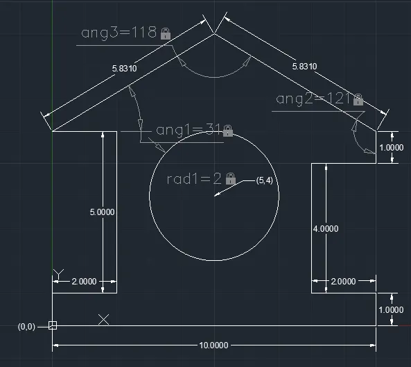
Q.5] Aim and Introduction:- Profile-wood exercise will explain the step by step procedure to create geomentry as shown
in the following figure using the Relative rectangular coordinate system:-
Procedure:-
1. Open AutoCAD and open a new drawing
2. Set the necessary limits and units
3. Type L at command window and press enter
4. Specify first point: type (0,0) at command prompt and press enter (as starting point)
5. Specify next point: Specify the next point in relative method like @10,0 and press enter
6. Specify next point: Specify the next point at @0,1 and press enter
7. Specify next point: Specify the next point at @-2,0 and press enter
8. Specify next point: Specify the next point at @0,4 and press enter
9. Specify next point: Specify the next point at @2,0 and press enter
10. Specify next point: Specify the next point at @0,1 and press enter
11. Specify next point: Specify the next point at @-5,3 and press enter
12. Specify next point: Specify the next point at @-5,-3 and press enter
13. Specify next point: Specify the next point at @0,2 and press enter
14. Specify next point: Specify the next point at @0,-5 and press enter
15. Specify next point: Specify the next point at @-2,0and press enter
16. Specify next point or close: Select the close option or Specify the next point at @0,-1 and press enter key
17. Specify next point: type circle at command prompt and press enter and specify the (5,4) point with radius 2
and save the drawing with proper file name.
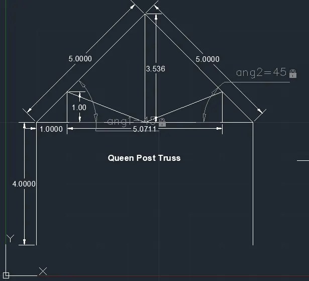
Q.6] Aim and Introduction:- Queen Post Truss exercise will explain the step by step procedure to create geomentry as
shown in the following figure using the Polar coordinate system:-
Procedure:
1. Open AutoCAD and open a new drawing
2. Set the necessary limits and units
3. Type L at command window and press enter
4. Specify first point: type (1,1) at command prompt and press enter (as starting point)
5. Specify next point: Specify the next point in relative method like @4<90 and press enter
6. Specify next point: Specify the next point at @5<45 and press enter
7. Specify next point: Specify the next point at @3.536<270 and press enter
8. Specify next point: Specify the next point at @2.536<180 and press enter
9. Specify next point: Specify the next point at @1<180 and press enter and join the other lines
10. Specify next point: Type mirror at command prompt and select the truss and mirror it
11. Specify next point or close: Select the close option or Specify the next point at @1<180 and press enter key and
save the drawing with proper file name.
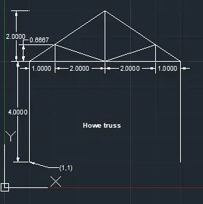
Q7] Aim and Introduction:- Howe Truss exercise will explain the step by step procedure to create geomentry as shown
in the following figure using the Relative rectangular coordinate system:-
Procedure:-
1. Open AutoCAD and open a new drawing
2. Set the necessary limits and units
3. Type L at command window and press enter
4. Specify first point: type (1,1) at command prompt and press enter (as starting point)
5. Specify next point: Specify the next point in relative method like @0,4 and press enter
6. Specify next point: Specify the next point at @3,2 and press enter
7. Specify next point: Specify the next point at @0,-2 and press enter
8. Specify next point: Specify the next point at @-2,0 and press enter
9. Specify next point: Specify the next point at @-1,0 and press enter
10. Specify next point: Specify the next point at @0,0.667 from point (9) and press enter and join the remaining lines
11. Specify next point: Type mirror at command prompt and select the truss and mirror it
12. Specify next point: Go to menu bar and save the drawing with proper file name.
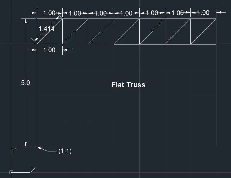
Q.8] Aim and Introduction:- Flat Truss exercise will explain the step by step procedure to create geomentry as shown
in the following figure using the Coordinate system:-
Procedure:-
1. Open AutoCAD and open a new drawing
2. Set the necessary limits and units
3. Type L at command window and press enter
4. Specify first point: type (1,1) at command prompt and press enter (as starting point)
5. Specify next point: Specify the next point in relative method like @0,5 and press enter
6. Specify next point: Specify the next point at @1,0 and press enter
7. Specify next point: Specify the next point at @0,-1 and press enter
8. Specify next point: Specify the next point at @-1,0 and press enter
9. Specify next point: Specify the next point at @1.414<45 and press enter
10. Specify next point: Type Copy at command prompt and select the truss and copy it
11. 10. Specify next point: Specify the next point at @4<270 and press enter
12. Specify next point: Go to menu bar and save the drawing with proper file name.
Q.9] Aim and Introduction:- Mono Pitch exercise will explain the step by step procedure to create geomentry as shown
in the following figure using the Relative Coordinate system:-
Procedure:-
1. Open AutoCAD and open a new drawing
2. Set the necessary limits and units
3. Type L at command window and press enter
4. Specify first point: type (1,1) at command prompt and press enter (as starting point)
5. Specify next point: Specify the next point in relative method like @2,0 and press enter
6. Specify next point: Specify the next point at @2,0 and press enter
7. Specify next point: Specify the next point at @2,0 and press enter
8. Specify next point: Specify the next point at @0,2 and press enter
9. Specify next point: Specify the next point at @0,0.667 after first 2.00 and press enter
10. Specify next point: Specify the next point at @0,1.333 after second 2.00 and press enter and join remaining points
11. Specify next point: Go to menu bar and save the drawing with proper file name.