Creation of Column Schedule and Drawing Template using AutoCad
Q1:
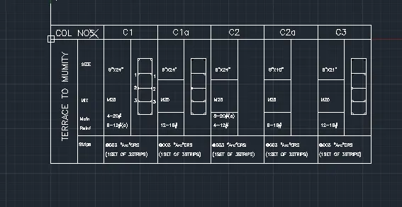
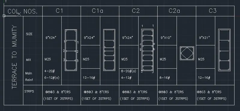
Aim: To create column schedule as shown in the figure using AutoCAD
Procedure:
Type "UNITS" in the command prompt and press enter.
In the unit tab, select the type as "Architectural" and insertion scale as "inches".
Click ok.
Select line command from the ribbon tab.
Specify the starting point by clicking anywhere on the workspace.
Specify the next point by keeping the cursor in the positive Y direction and click on it.
Specify the next point by keeping the cursor in the positive X direction and click on it.
Specify the next point by keeping the cursor in the negative Y direction and click on it.
Specify the next point by keeping the cursor in the negative Y direction and click on it.
Press "esc".
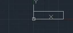
Select the previously created object in the workspace.
Type "COPY" in the Command prompt and press enter.
Select the left bottom corner point as base point and press enter.
Move the copied object along the base point in X plane.
Keep the cursor on right bottom point and click.
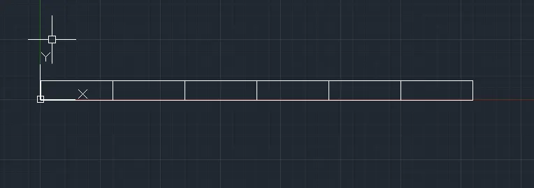
Repeat the same procedure another five times to create upper row.
Now press "esc".
Type "dimstyle" in the command prompt and press enter.
From the ribbon tab, select "Annotate".
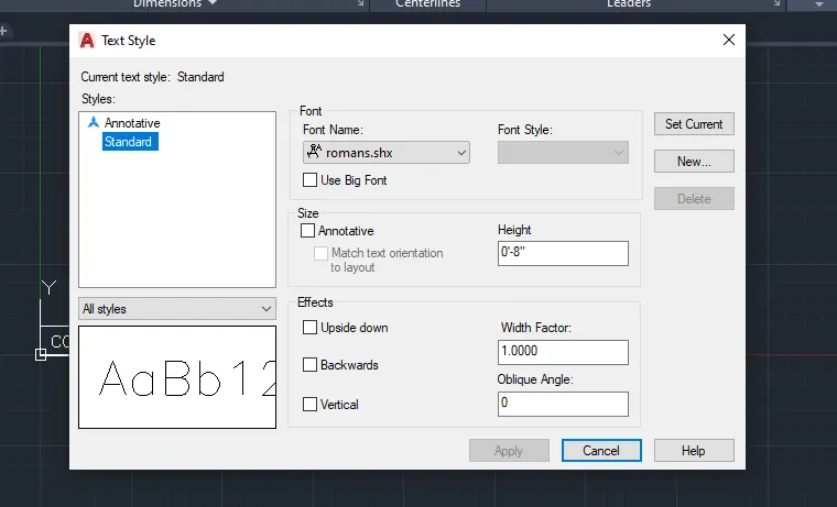
Under text, select "manage text styles".
Specify the text height as 8" and font as "roman.shx"
Click ok.
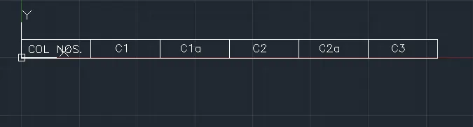
Select "text" toool from ribbon tab.
From the drop down list select "single line" text.
Now the keep the pointer in the left box and click as per the alignment required.
Type "Column Nos." and press enter.
Now the keep the pointer in the left box and click as per the alignment required.
Type "C1" and press enter.
Now the keep the pointer in the left box and click as per the alignment required.
Type "C1a" and press enter.
Now the keep the pointer in the left box and click as per the alignment required.
Type "C2" and press enter.
Now the keep the pointer in the left box and click as per the alignment required.
Type "C2a" and press enter.
Now the keep the pointer in the left box and click as per the alignment required.
Type "C3" and press enter.
Select line command from the ribbon tab.
Specify the starting point by clicking anywhere on the workspace.
Specify the next point by keeping the cursor in the positive Y direction and click on it.
Specify the next point by keeping the cursor in the positive X direction and click on it.
Specify the next point by keeping the cursor in the negative Y direction and click on it.
Specify the next point by keeping the cursor in the negative Y direction and click on it.
Press "esc".
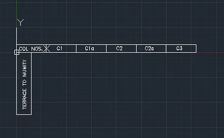
Select "text" toool from ribbon tab.
From the drop down list select "single line" text.
Now the keep the pointer in the left box and click as per the alignment required.
Type "Terrace To Mumity" and press enter.
Select the previously created object in the workspace.
Type "COPY" in the Command prompt and press enter.
Select the left bottom corner point as base point and press enter.
Move the copied object along the base point in X plane.
Keep the cursor on right bottom point and click.
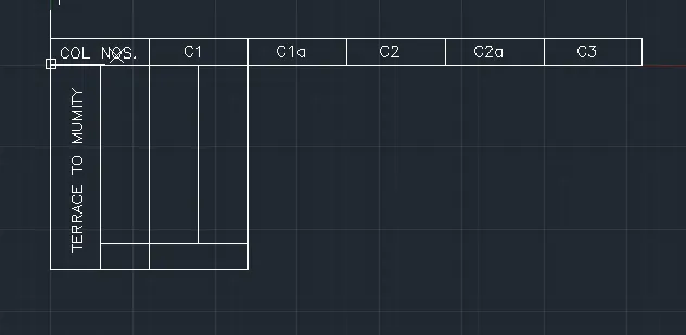
Select line command from the ribbon tab.
Specify the starting point as the left corner point of previously created object.
Specify the next point by keeping the cursor in the positive Y direction and click on it.
Specify the next point by keeping the cursor in the positive X direction and click on it.
Specify the next point by keeping the cursor in the negative Y direction and click on it.
Specify the next point by keeping the cursor in the negative Y direction and click on it.
Press "esc".
Select line command from the ribbon tab.
Specify the starting point as the left corner point of previously created object.
Specify the next point by keeping the cursor in the positive Y direction and click on it.
Specify the next point by keeping the cursor in the positive X direction and click on it.
Specify the next point by keeping the cursor in the negative Y direction and click on it.
Specify the next point by keeping the cursor in the negative Y direction and click on it.
Press "esc".
Draw line at a suitable distance from bottom using line tool from ribbon tab.
Type "trim" in the command tab and press enter.
Trim the additional lines to get object as per the figure.
Press "esc".
Select the previously created object in the workspace.
Type "COPY" in the Command prompt and press enter.
Select the left bottom corner point as base point and press enter.
Move the copied object along the base point in X plane.
Keep the cursor on right bottom point and click.
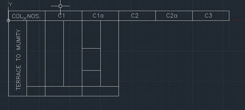
Select line command from the ribbon tab.
As per the given figure, draw a line at a suitable distance.
Press "esc".
Select line command from the ribbon tab.
As per the given figure, draw a line at a suitable distance.
Press "esc".
Select the previously created object in the workspace.
Type "COPY" in the Command prompt and press enter.
Select the left bottom corner point as base point and press enter.
Move the copied object along the base point in X plane.
Keep the cursor on right bottom point and click.
Repeat the same procedure another three times to create similar style.
Now press "esc".
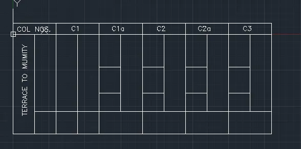
Select "text" toool from ribbon tab.
From the drop down list select "single line" text.
Now the keep the pointer in the right box of "COL NOS" column and click as per the alignment required.
Type "Size" and press enter.
Now the keep the pointer in the right box of "COL NOS" column and click as per the alignment required.
Type "MIX" and right click.
Now the keep the pointer in the right box of "COL NOS" column and click as per the alignment required.
Type "MAIN RONF" and right click.
Now the keep the pointer in the right box of "COL NOS" column and click as per the alignment required.
Type "MIX" and right click.
Now the keep the pointer in the right box of "COL NOS" column and click as per the alignment required.
Type "STRIPS" and right click.
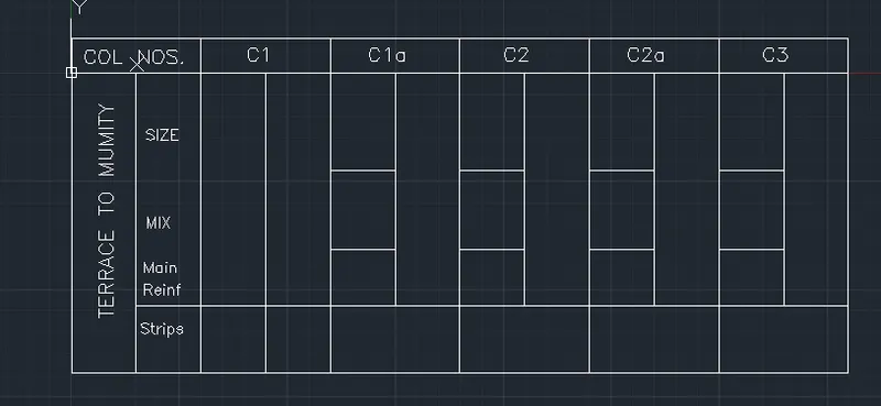
Select "text" tool from ribbon tab.
From the drop down list select "single line" text.
Now the keep the pointer in the left box of "C1" column and click as per the alignment required.
Type "9"x24"" and press enter.
Now the keep the pointer in the left box of "C1" column and click as per the alignment required.
Type "M25" and right click.
Now the keep the pointer in the left box of "C1" column and click as per the alignment required.
Type "4-20#" press enter, type "6-12#" and right click.
Now the keep the pointer in the left box of "C1" column and click as per the alignment required.
Type "4-20#" press enter, type "(1SET OF 3STRIPS)" and right click.
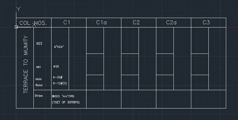
Select "text" tool from ribbon tab.
From the drop down list select "single line" text.
Now the keep the pointer in the left box of "C1a" column and click as per the alignment required.
Type "9"x24"" and press enter.
Now the keep the pointer in the left box of "C1a" column and click as per the alignment required.
Type "M25" and right click.
Now the keep the pointer in the left box of "C1a" column and click as per the alignment required.
Type "12-16#" and right click.
Now the keep the pointer in the left box of "C1a" column and click as per the alignment required.
Type "4-20#" press enter, type "(1SET OF 3STRIPS)" and right click.
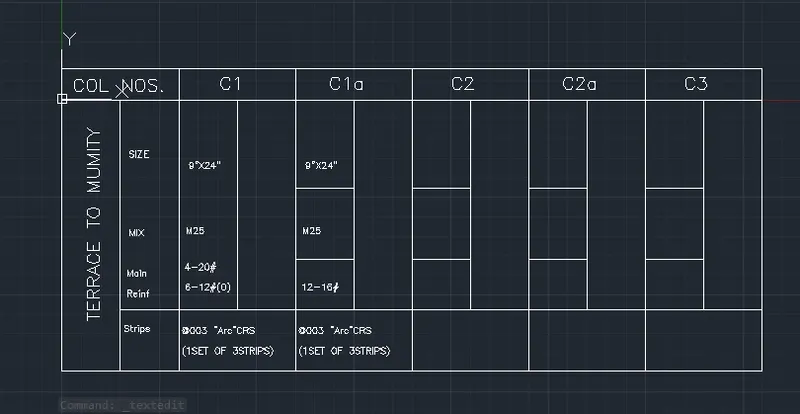
Select "text" tool from ribbon tab.
From the drop down list select "single line" text.
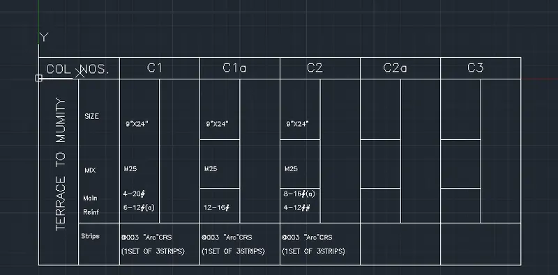
Now the keep the pointer in the left box of "C2" column and click as per the alignment required.
Type "9"x24"" and press enter.
Now the keep the pointer in the left box of "C2" column and click as per the alignment required.
Type "M25" and right click.
Now the keep the pointer in the left box of "C2" column and click as per the alignment required.
Type "8-16#", press enter type "4-12#" and right click.
Now the keep the pointer in the left box of "C2" column and click as per the alignment required.
Type "4-20#" press enter, type "(1SET OF 3STRIPS)" and right click.
Select "text" tool from ribbon tab.
From the drop down list select "single line" text.
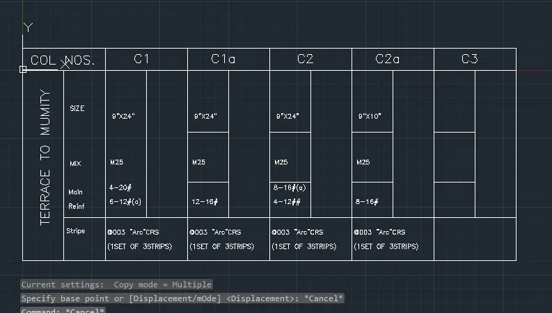
Now the keep the pointer in the left box of "C2a" column and click as per the alignment required.
Type "9"x10" and press enter.
Now the keep the pointer in the left box of "C2a" column and click as per the alignment required.
Type "M25" and right click.
Now the keep the pointer in the left box of "C2a" column and click as per the alignment required.
Type "8-20#", press enter type "4-12#" and right click.
Now the keep the pointer in the left box of "C2" column and click as per the alignment required.
Type "4-20#" press enter, type "(1SET OF 3STRIPS)" and right click.
ϕ
Select "text" tool from ribbon tab.
From the drop down list select "single line" text.
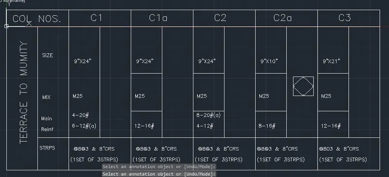
Now the keep the pointer in the left box of "C3" column and click as per the alignment required.
Type "9"x21" and press enter.
Now the keep the pointer in the left box of "C3" column and click as per the alignment required.
Type "M25" and right click.
Now the keep the pointer in the left box of "C3" column and click as per the alignment required.
Type "12-16#" and right click.
Now the keep the pointer in the left box of "C3" column and click as per the alignment required.
Type "4-20#" press enter, type "(1SET OF 3STRIPS)" and right click.
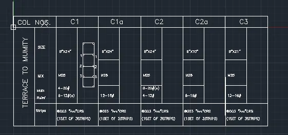
Use rectangle tool from ribbon tab.
Draw a rectangle as per reinforcement specification.
Select line tool from ribbon rab and draw a line at every one fourth distance.
Select circel tool from ribbon tab and draw a circle with refernce to the reinforcement.
Place the circle in the respective place.
Select Hatch tool from ribbon tab.
Select hatch color option and select the color as black.
Use hatch to color the circle.
Select the previously created object in the workspace.
Type "COPY" in the Command prompt and press enter.
Select the left bottom corner point as base point and press enter.
Move the copied object along the base point in X plane.
Keep the cursor on right bottom point of C1a and C3, then click.
Select the previously created object in the workspace.
Type "COPY" in the Command prompt and press enter.
Select the left bottom corner point as base point and press enter.
Move the copied object along the base point in X plane.
Keep the cursor on right bottom point of C2, then click.
Use text tool from ribbon tab to add refernce for section
Q2:
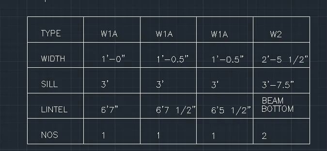
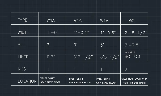
Aim: To create the window schedule as per the given figure using AutoCAD.
Procedure:
Type "UNITS" in the command prompt and press enter.
In the unit tab, select the type as "Architectural" and insertion scale as "inches".
Click ok.
Select line command from the ribbon tab.
Specify the starting point as (0,0) and press enter.
Keep the cursor in positive X direction and enter the length as 400.
Keep the cursor in positive Y direction and enter the length as 2.
Keep the cursor in negaive X direction and enter the length as 400.
Keep the cursor in negaive Y direction and enter the length as 2.
Type "offset" in the command prompt and press enter.
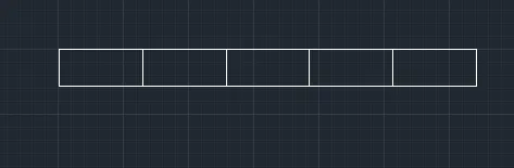
Specify the offset distance as 80 and press enter.
Select the 2unit length to offset and click by keeping the cursor in positive X direction.
Repeat the offset for four time by selecting the previous offsetted objects.
Select "text" tool from ribbon tab.
From the drop down list select "single line" text.
Now the keep the pointer in the left box and click as per the alignment required.
Type "TYPE" and press enter.
Click on the next box to insert text.
Type "W1A" and press enter.
Click on the next box to insert text.
Type "W1A" and press enter.
Click on the next box to insert text.
Type "W1A" and press enter.
Click on the next box to insert text.
Type "W2" and press enter.
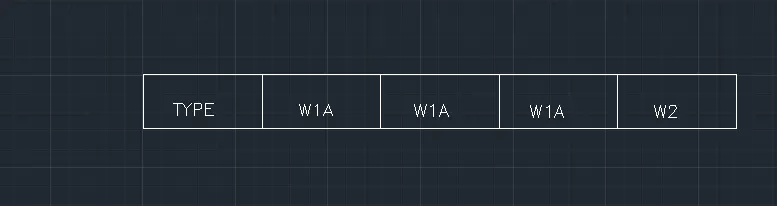
Select all the objects along with the texts.
Type "COPY" in the command prompt and press enter.
Select the top right corner as base point.
Copy down the selected objects to the bottom right corner and press enter.
Select the text "TYPE" and double click on it.
Edit the text as "WIDTH".
Click on the text "W1A" and edit it as 1'-0".
Now Click on the next text "W1A" and edit it as 1'-0.5".
Now Click on the next text "W1A" and edit it as 1'-0.5".
Now Click on the next text "W2" and edit it as 2'-5 1/2".
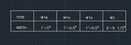
Select the previously created object along with the texts.
Type "COPY" in the command prompt and press enter.
Select the top right corner as base point.
Copy down the selected objects to the bottom right corner and press enter.
Select the text "WIDTH" and double click on it.
Edit the text as "BILL".
Click on the text 1-0" and edit it as 3'.
Now Click on the next text 1'0.5" and edit it as 3'.
Now Click on the next text 1'0.5" and edit it as 3'.".
Now Click on the next text 2'-5 1/2" and edit as 3'-7.5" .
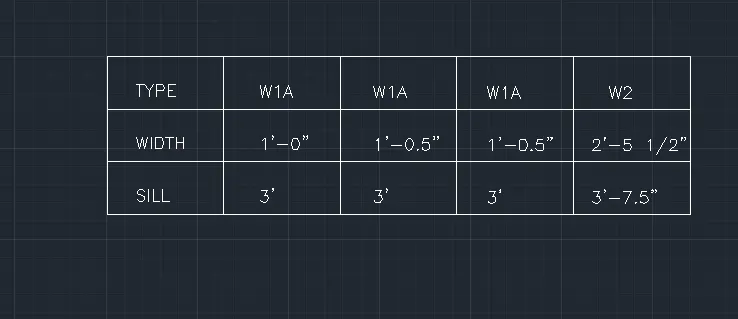
Select the previously created object along with the texts.
Type "COPY" in the command prompt and press enter.
Select the top right corner as base point.
Copy down the selected objects to the bottom right corner and press enter.
Select the text "SILL" and double click on it.
Edit the text as "LINTEL".
Click on the text 3' and edit it as 6'7".
Now click on the text 3' and edit it as 6' 7 1/2".
Now click on the text 3' and edit it as 6' 5 1/2".
Now click on the text 3' 7.5" and edit it as BEAM BOTTOM.
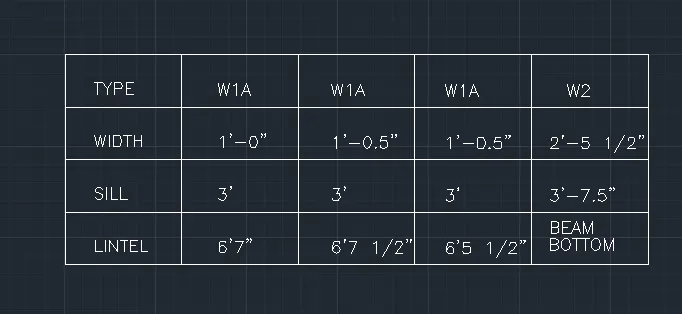
Select the previously created object along with the texts.
Type "COPY" in the command prompt and press enter.
Select the top right corner as base point.
Copy down the selected objects to the bottom right corner and press enter.
Select the text "LINTEL" and double click on it.
Edit the text as "NOS".
Click on the text 6'7" and edit it as 1.
Now click on the text 6' 7 1/2" and edit it as 1.
Now click on the text 6' 5 1/2" and edit it as 1.
Now click on the text BEAM BOTTOM and edit it as 2.
Select the previously created object along with the texts.
Type "COPY" in the command prompt and press enter.
Select the top right corner as base point.
Copy down the selected objects to the bottom right corner and press enter.
Select the text "NOS" and double click on it.
Edit the text as "LOCATION".
Click on the text 1 and edit it as TOILET SHAFT NEAR FIRST FLOOR.
Now click on the text 1 and edit it as TOILET SHAFT SIDE GROUND FLOOR.
Now click on the text 1 and edit it as TOILET SHAFT SIDE THIRD FLOOR.
Now click on the text 2 and edit it as TOILET NEAR COURTYARD FIRST SECOND FLOOR.
Q3:
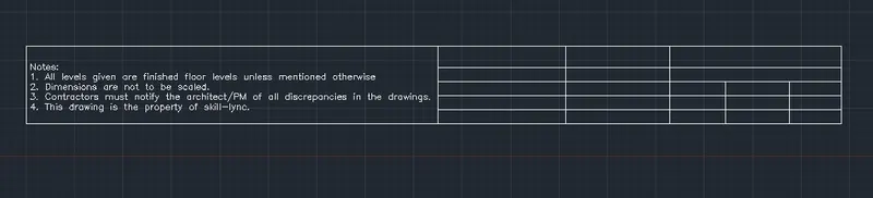
AIM: To create the drawing template as shown in the figure.
Procedure:
Select line tool from ribbon tab.
Specify the starting point as (0,0) in the command prompt and press enter.
Specify the next point as (@531,0) in the command prompt and press enter.
Specify the next point as (@165,0) in the command prompt and press enter.
Specify the next point as (@134,0) in the command prompt and press enter.
Specify the next point as (@221,0) in the command prompt and press enter.
Specify the next point as (0,@125) in the command prompt and press enter.
Specify the next point as (@-1051,0) in the command prompt and press enter.
Click close.

Select line tool from ribbon tab.
Specify the starting point as (531,125) and press enter.
Specify the next point as (@0,-125) in the command prompt and press enter.
Press esc.
Select line tool from ribbon tab.
Specify the starting point as (695,125) and press enter.
Specify the next point as (@0,-125) in the command prompt and press enter.
Press esc.
Select line tool from ribbon tab.
Specify the starting point as (1058,125) and press enter.
Specify the next point as (@0,-125) in the command prompt and press enter.
Press esc.

Type offset in the command prompt and press enter.
Specify the offset distance as 25 and press enter.
Select the second column line and offset it in downward direction.
Type offset in the command prompt and press enter.
Specify the offset distance as 18 and press enter.
Select the second column line and offset it in downward direction.
Type offset in the command prompt and press enter.
Specify the offset distance as 25 and press enter.
Select the third column line and offset it in downward direction.
Type offset in the command prompt and press enter.
Specify the offset distance as 18 and press enter.
Select the third column line and offset it in downward direction.
Similarly use offset command to acheive the divisions as shown in the figure

Select the text tool from ribbon tab.
From the drop down, select single line text.
Click on the point from where the text has to start.
Type the first line and press enter.
Type the second line and press enter.
Similarly type all the lines one below the other.
Select the text tool from ribbon tab.
From the drop down, select single line text.
Click on the point from where the text has to start.
Type "Project: Pearl villas" .
Place the cursor in the next line and type "Arcitect:".
Place the cursor where the text has to be inserted next and type "Drawing Title".
Place the cursor where the text has to be inserted next and type "Drawing No".
Place the cursor where the text has to be inserted next and type "Issued date".
Place the cursor where the text has to be inserted next and type "Rev No".
Place the cursor where the text has to be inserted next and type "Drawing list".
Place the cursor where the text has to be inserted next and type "Date".
Place the cursor where the text has to be inserted next and type "Issued by".
Place the cursor where the text has to be inserted next and type "Scale".
Place the cursor where the text has to be inserted next and type "1.75".

Q4:
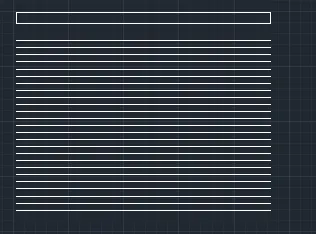
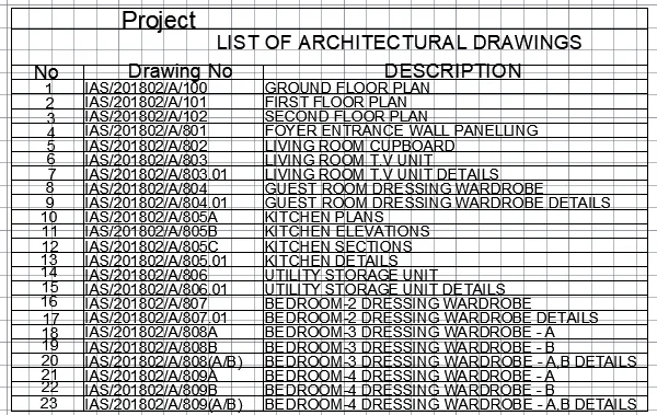
Aim: To create the list of drawing schedule as shown in the figure.
Procedure:
Type "units" in the command prompt and press enter.
Select the units as "Architectural" and click ok.
From the ribbon tab, select the line tool.
Specify the starting point in the workspace.
Specify the next point as (@340",0) in the command prompt and press enter.
Specify the next point as (@0,-8") in the command prompt and press enter.
Specify the next point as (@-340",0) in the command prompt and press enter.
Specify the next point as (@0,8") in the command prompt and press enter.

Type "offset" in the command prompt and press enter.
Specify the offset distance as 20" in the command prompt.
Select the bottom line to offset.

Type "offset" in the command prompt and press enter.
Specify the offset distance as 8" in the command prompt.
Select the bottom line to offset.
Similarly do offset for all the lines.
Select line tool from ribbon tab.
Connect all the lines on both the sides.
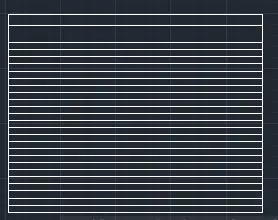
Type "offset" in the command prompt and press enter.
Specify the offset distance as 40" in the command prompt.
Select the left vertical line to offset.

Type "offset" in the command prompt and press enter.
Specify the offset distance as 100" in the command prompt.
Select the previously offsetted vertical line to offset.
Type "offset" in the command prompt and press enter.
Specify the offset distance as 100" in the command prompt.
Select the previously offsetted vertical line to offset.
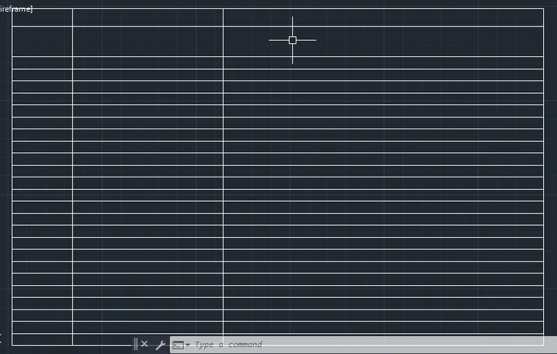
Select the Annotate tool from the ribbon tab.
Select "Manage text style" from the drop down list available.
Select the font name as "Arial" and font style as "bold".
Enter the text height as 6" and click ok.
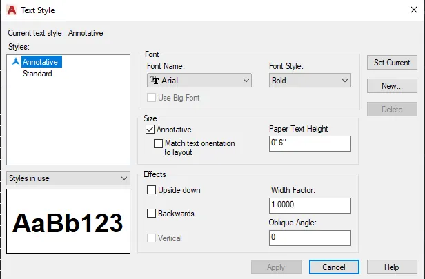
Select the text tool from ribbon tab.
From the drop down list, select the "single line".
Click on the cursor to start entering the text.
Text pointer appears, enter the text as "Project".
Click on the cursor to start entering the next text.
Text pointer appears, enter the text as "LIST OF ARCHITECTURAL DRAWINGS".
Click on the cursor to start entering the next text.
Text pointer appears, enter the text as "NO".
Click on the cursor to start entering the next text.
Text pointer appears, enter the text as "DRAWINGS".
Click on the cursor to start entering the next text.
Text pointer appears, enter the text as "DESCRIPTION".
Select all the texts using cursor.
In the ribbon tb, go to properties section.
Click "By layer" in the properties.
Select the color as "black".
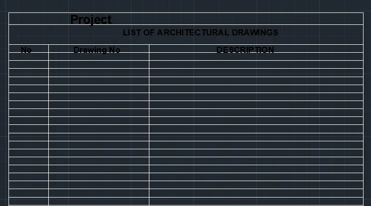
Similarly to type the given text in the workspace use text tool.
Select the text tool from ribbon tab.
From the drop down list, select the "single line".
Click on the cursor to start entering the text.
Q5:
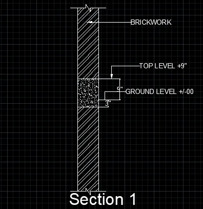
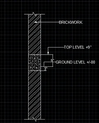
AIM: Create the Beam detail as shown in the figure and provide text for Top level and Ground level wherever given.
PROCEDURE:
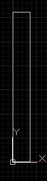
Select line from the ribbon tab.
Specify the starting point as (0,0) in the command prompt and press enter.
Specify the next point as (@0,3') in the command prompt and press enter.
Specify the next point as (@0,3") in the command prompt and press enter.
Specify the next point as (@0,9") in the command prompt and press enter.
Specify the next point as (@0,2.4') in the command prompt and press enter.
Specify the next point as (@9",0) in the command prompt and press enter.
Specify the next point as (@0,-2.4') in the command prompt and press enter.
Specify the next point as (@0,-9") in the command prompt and press enter.
Specify the next point as (@0,-3") in the command prompt and press enter.
Specify the next point as (@0,-3') in the command prompt and press enter.
Specify the next point as (@-9",0) in the command prompt and press enter.
Type "line" in the command prompt and press enter.
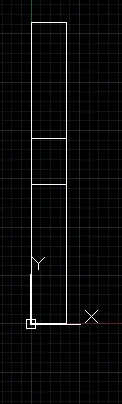
Specify the starting point as (0,3') in the command prompt and press enter.
Specify the next point as (@9",0) in the command prompt and press enter.
Press "esc".
Type "line" in the command prompt and press enter.
Specify the starting point as (0,4') in the command prompt and press enter.
Specify the next point as (@9",0) in the command prompt and press enter.
Press "esc".
Type "hatch" in the command prompt and press enter.
Hatch creation tool box opens.
From the pattern menu, select the suitable hatch as given in the figure to represent brick work.
Move the pointer to the closed area to be hatched and click to hatch the layer.
Adjust the scale to view the hatch.
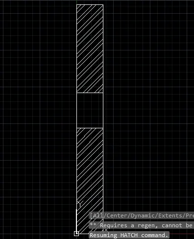
Type "hatch" in the command prompt and press enter.
Hatch creation tool box opens.
From the pattern menu, select the suitable hatch as given in the figure to represent concrete.
Move the pointer to the closed area to be hatched and click to hatch the layer.
Adjust the scale to view the hatch.
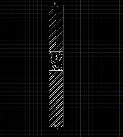
Select dimension tool from ribbon tab to measure the dimensions.
Select the first point and drag the pointer to specify the next point.
Now the tool displays the dimension.
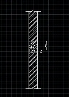
Similarly to type the given text in the workspace use text tool.
Select the Annotation tool from ribbon tab.
From the drop down list, select the "leader".
Click on the cursor to start the leader and adjust the height using cursor.
Enter the text as "Ground level +/-00".
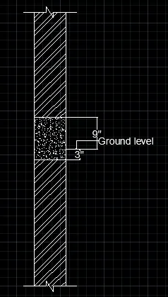
Similarly to type the given text in the workspace use text tool.
Select the Annotation tool from ribbon tab.
From the drop down list, select the "leader".
Click on the cursor to start the leader and adjust the height using cursor.
Enter the text as TOP LEVEL+9".
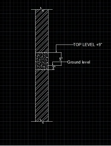
Similarly to type the given text in the workspace use text tool.
Select the Annotation tool from ribbon tab.
From the drop down list, select the "leader".
Click on the cursor to start the leader and adjust the height using cursor.
Enter the text as "BRICKWORK".
Select the text tool from ribbon tab.
From the drop down list, select the "single line".
Click on the cursor to start entering the text.
Enter the text as " Section 1".