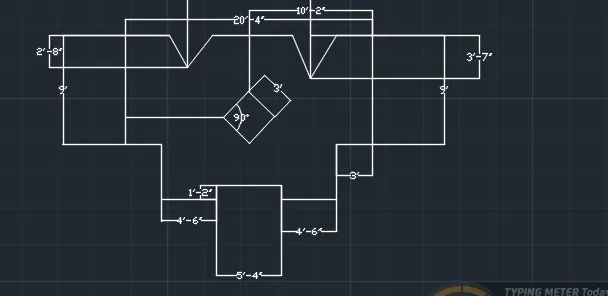
Drafting of various geometries using Chamfer, Fillet tool in AutoCad
CHALLENGE 3 ANSWERS
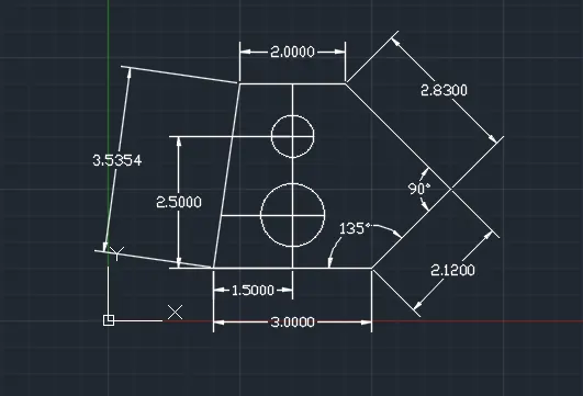
1.Q.A
AIM:- To draw a given geometry by using decimal units.
PROCEDURE:- To open the AutoCAD software and run the application then to set the units and limits .use Ortho mode and polar mode.
Then follow the below points to draw line diagram
- L enter
- Specify the first point is and enter.
- Enter the next point is 3 units and
- Then give the next point is @2.12<45 and enter
- Enter the next point is @2.83<135 and
- Enter the next point is 2 units and
- Enter the next point is close and `
- Take off set command and draw a two line parallel to the selected base line with offset distance of 1 unit and 2.50 units .
- Take circle command and with diameter 1.20 and 0.80 and enter.
- Use dim command and give dimensions of the lines.
2Q.A
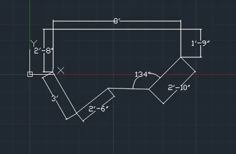
AIM:- To draw a given geometry by using ARCHITECTURAL UNITS
PROCEDURE:- To open the AutoCAD software and run the application then to set the units and limits .use Ortho mode and polar mode.
Then follow the below points to draw line diagram
- L enter
- Specify the first point is and enter.
- Enter the next point is 2’10” with angle 45 degrees and enter.
- Enter the next point is 1’9” and
- Enter the next point is 8” and
- Enter the next point is 2’8” and
- Enter the next point is @3’<315 and
- Enter the next point is @ 2’6”<90 and enter and use close command.
- Use dim command and give the dimensions of line and angles.
3Q.A
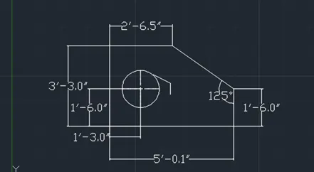
AIM:- To draw a given geometry by using ENGINEERING UNITS.
PROCEDURE:- To open the AutoCAD software and run the application then to set the units and limits .use Ortho mode and polar mode.
Then follow the below points to draw line diagram
- L enter
- Specify the first point is and enter.
- Enter the point as 1’ 6.0” and enter.
- Enter the next point is 5’0.1” and enter.
- Enter the point as 3’3.0” and enter.
- Enter the point as 2’6.5”and enter
- Use close command
- Take off set command in to draw a lines with offset distance is 1’3.0” and 1’6.0” and select the intersection point and draw a circle with circle command with dia is 1’6.0”
- Use trim command and trim the extra lines.
- Use the dim command and give the dimensions of lines.
4.Q.A
AIM:- To draw a given geometry by using decimal units.
PROCEDURE:- To open the AutoCAD software and run the application then to set the units and limits .use Ortho mode
Then follow the below points to draw line diagram
- L enter
- Specify the first point is and enter.
- Enter the next point is 3 units and
- Enter the next point is 50and enter.
- Enter the next point is 50 and enter.
- Enter the next point is 50 and enter.
- Enter the next point is 2 and
- Enter the next point is 00 and enter.
- Enter the next point is 2.50 and
- Enter the next point is 2.00and
- Enter the next point is 00 and enter.
- Use close command and use dim command and give the dimensions of lines.
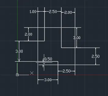
5Q.A
AIM:- To draw a given geometry by using decimal units.
PROCEDURE:- To open the AutoCAD software and run the application then to set the units and limits .use Ortho mode
Then follow the below points to draw line diagram
- L enter
- Specify the first point is and enter.
- Enter the next point is 50 units and enter.
- Enter the next point is 6 units and
- Enter the next point is 50 units and enter.
- Enter the next point is 6 units or close command and
- Draw a center lines in that geometry and mark centers.
- Take off set command in required direction and draw lines with offset distances is 50 units in both sides and take that line as reference line and again draw offset line with a distance of 4.25 units.
- Use trim command and trim the extra lines.
- Use annotate in display command and give the centerline marking of circles and use dim command and give the dimensions of the lines.
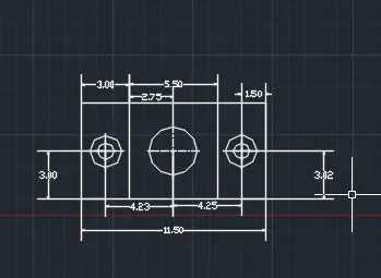
6Q.A
AIM:- To draw a given geometry by using decimal units.
PROCEDURE:- To open the AutoCAD software and run the application then to set the units and limits .Use Ortho mode and polar mode.
Then follow the below points to draw line diagram
- Select a rectangle command and enter.
- Specify the first point is and enter.
- Give the dimension of rectangle is 2 and 1.5 units.
- Take the offset command and draw a lines with offset distance is 0.5 units where we required.
- Use trim command and trim out the extra lines.
- Take Line command draw a reference line and give the projections of first drawing by using extend line command. And remaining lines are joined by line command. And exit or esc
- Take Line command draw a reference line in vertical direction and give the projections of second drawing by using extend line command. And remaining lines are joined by line command. And exit or esc
- Use trim command to trim the extra lines.

7Q.A
AIM:- To draw a given geometry by using decimal units.
PROCEDURE:- To open the AutoCAD software and run the application then to set the units and limits .use Ortho mode
Then follow the below points to draw line diagram
- L enter
- Specify the first point is and enter.
- Enter the next points is 100 units and enter.
- Enter the next point is 210 units and enter.
- Enter the next point is 75 units and enter.
- Take off set command and draw a line with parallel to the 210 units line with offset of 10 units and 40 units .and also draw a offset lines in opposite direction with offset distances is 20 units and 90 units in both sides with these lines makes a rectangle and trim the extra lines with using of trim command.
- Draw a circles with given radius or diameter by selecting the circle command with center line.
- Use fillet command and give radius and select multiple and select the object and enter.
- Draw a center lines in circle in that geometry and mark centers.
- Use ESC or close command and enter.
- Use DIM command and give the dimensions of the lines and angle and radius.
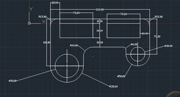
8Q.A
AIM:- To draw a given geometry by using decimal units.
PROCEDURE:- To open the AutoCAD software and run the application then to set the units and limits .use Ortho mode
Then follow the below points to draw line diagram
- L enter
- Specify the first point is and enter.
- Give the next point with distance of 8.550 units and enter.
- Take a circle command and draw the circles with required diameter or radius and use copy command copy the two circles and then draw another two circles in between those circles.
- Take the tangent line and joint the two circles.
- Trim the extra lines with trim command .
- Use dim command and give the dimensions of the lines.
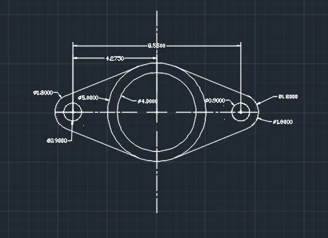
9Q.A
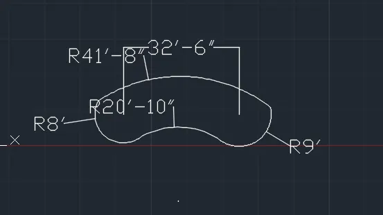
AIM:- To draw a given geometry by using ARCHITECTURAL UNITS
PROCEDURE:- To open the AutoCAD software and run the application then to set the units and limits .use Ortho mode
Then follow the below points to draw line diagram
- L enter
- Give the next point as 32’6” and enter.
- Take the endpoint as center on both sides draw the circle by using circle command with radius of 8’ and9’ and enter.
- Draw a another circle with tangent to the two circles with radius of 20’10” and draw another circle with same above procedure with radius is 41’8” and enter.
- Take mirror command select the circle of radius is 41’8” and mirror it to down words and trim the extra line by using the trim command .
- Use dim command and give the dimension and radius of the lines.
10.Q.A
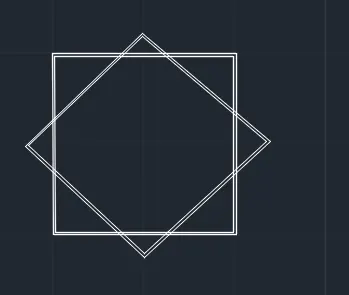
AIM:- To draw a given geometry by using the multiline command .
PROCEDURE:- To open the AutoCAD software and run the application then to set the units and limits .use Ortho mode and polar mode.
Then follow the below points to draw line diagram
- Give mL command and enter
Specify the first point is and other points and use close command .
Again use the ml command give the first point and other point and close
11Q.A
AIM:- To draw a given geometry by using ARCHITECTURAL UNITS
PROCEDURE:- To open the AutoCAD software and run the application then to set the units and limits .use Ortho mode and polar mode.
Then follow the below points to draw line diagram
- L enter
- Specify the first point is and enter.
- Give the next point 9’ an enter.
- The give the next point is 3’ to left side.
- Then specify the next point to down is 4’6” and enter.
- Then specify the next point to down is 4’6” and enter.
- Give the next point is 1’2”to upside and enter.
- Give the next point is 2’8”to left side and enter.
- Draw a reference line and use mirror command and select thetotal object and give the base point and mirror it. And enter
- Draw a square by giving length of 3’ and copy that inside the geometry .
- Use off set command and draw a two line with of set distance of 2’8” and 3’7” from top base line
- And give the angles and draw a line in top side and remaining line are draw by using the line command.
- Use trim command and trim out the extra lines.
- Use DIM command and give the dimensions of the lines.
- Press ESC