Creating a Floor plan, Footing detail and Isometric view using AutoCad
ANSWERS- CHALLENGE 2
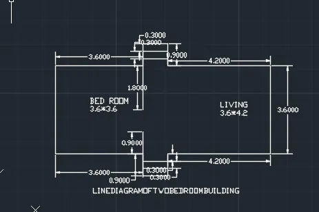
AIM:- To draw a Line diagram of a two bedroom building.
PROCEDURE:- To open the AutoCAD software and run the application then to set the units and limits .use ortho mode
Then follow the below points to draw line diagram
- L enter
- Specify the first point is and enter.
- Enter the next point is 60 and enter.
- Then give the next point is 0.9 and enter
- Enter the next point is 1 and
- Enter the next point is 9 and enter.
- Enter the next point is 20and enter.
- Enter the next point is 60 and enter.
- Enter the next point is 20 and enter.
- Enter the next point is 9 and enter.
- Enter the next point is 1 and
- Enter the next point is 60 and enter.
- Enter the next point is 9 and enter.
- Enter the next point is 60 and enter.
- Use close command.
- Take off set command and select the object and give distance of offset os 0.300 and enter how many off sets we need both sides for stair case purpose and enter. exit
- Again we use line command and to draw a two lines are 1.80 and 0.90 by specify the first point then enter simultaneously. Exit
- Take text command and mention the names of rooms
- Take DIM command and specify the dimensions. Esc
-
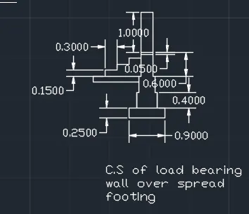
AIM:- To draw Cross- section of load bearing wall over spread footing.
PROCEDURE:- To open the AutoCAD software and run the application then to set the units and limits .use ortho mode
Then follow the below points to draw line diagram
- L enter and specify the first point.
- Give the next point as 0.90,0.25,0.90and 0.25 or close the rectangle.
- Draw a center line on top of the rectangle by (l enter and press shift keyand right click on mouse the it shows mid point of that line then draw a line perpendicular to that line as vertical)
- Take off set command ,then select object and give offset distances is 250,0.200,0.150 on both sides simultaneously.
- Again take offset command and select object (i.e rectangle top side parallel to rectangle) with off set distances is 0.400,0.400,0.600,0.050 and 1.000
- Take line command and enter then select the first point as corner of the base of wall and give distance of 1.15 and enter.
- Take off set command and select the object (i.e 1.15 length line) and give offset distance is 0.150 and enter top and bottomhow much we need tene exit.
- Again take offset command and select the object and give offset distance is 0.300 and enter how much we need.
- Trim the extra lines by using TRIM command .
- Use DIM command and annote the dimensions of the structure.
- Use text command and enter the name of the drawing.
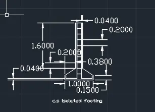
AIM:- To draw Cross- section of isolated footing.
PROCEDURE:- To open the AutoCAD software and run the application then to set the units and limits .use ortho mode and polar mode.
Then follow the below points to draw line diagram
- L enter and specify the first point enter
- Give the distance of 0.150 to down words
- Then Give the distance of 1 in right side and enter
- Then give the distance 0.150 to upword and exit.
- Take off set command and select the object (i.e base line) and give off set distance is 0.400 and enter.
- Draw a center line on top of the base line by (L enter and press shift key and right click on mouse the it shows mid point of that line then draw a line perpendicular to that line as vertical)
- Take off set command and then select the object that is center line with of set distance is 0.12 on both sides and enter.
- Trim the extra line by using TRIM command .
- Take line command and select polar mode and draw a line slope line on both sides
- Take off set command and draw a line of with offset distance of 0.400 on both side and enter.
- Select the top of the lin and take offset command and draw a offset line by distance of 0.200 to down word how many we need and enter.
- Take line command ad draw a line of distance is 0.380 right side and 0.100 up word and copy that to opposite side by selecting the object and base point and enter.
- Use trim command and trim the extra lines
- Use DIM command and annote the dimensions of the structure.
- Use text command and enter the name of the drawing.
-
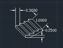
AIM:- To draw a isometric view os steps with given dimensions.
PROCEDURE:- To open the AutoCAD software and run the application then to set the units and limits .use ortho mode
Then follow the below points to draw line diagram
- Take l command and enter the first point
- Give the next point as 0.300 to left side
- Then give the next points 0.150 up word and 0.300 right side simultaneously how many stairs we required and final we give the 0.150 to down and use close command and enter.
- Take copy command and select the object and distance from that object and slest the base point and give that where we want and enter.
- Take line command and draw the remaining lines and
- Use TRIM command and trim the extra line and press esc button.
- Use DIM command and annote the dimensions of the structure.
-
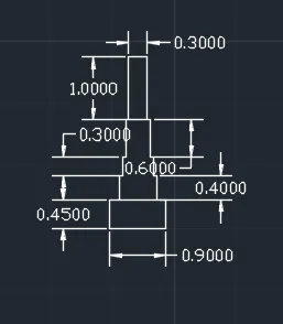
AIM:- To draw Cross- section of load bearing wall showing foundation details.
PROCEDURE:- To open the AutoCAD software and run the application then to set the units and limits .use ortho mode
Then follow the below points to draw line diagram
- Take a rectangle command and select the first point and give the dimension of remaining points as 0.90 and 0.45 then enter.
- Draw a center line on top of the rectangle by (l enter and press shift keyand right click on mouse the it shows mid point of that line then draw a line perpendicular to that line as vertical)
- Take off set command and select the object (center line) and give the offset distances is 0.300 ,0.250,0.200 and 0.150 simultaneously on both sides.
- Take off set command and select the top of the rectangle line and give the offset distance 0.400 and then select than t line and give the offset distance is 0.300 and enter and again select that line and give the offset distance of 0.600 and 1.600 enter .
- Use the TRIM command and trim the extra lines.
- Use DIM command and annote the dimensions of the structure.
- Use text command and enter the name of the drawing.
-
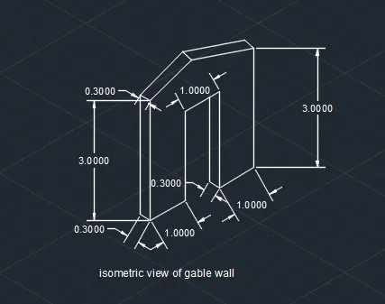
AIM:- To draw a ISOMETRIC VIEW OF GABLE WALL.
PROCEDURE:- To open the AutoCAD software and run the application then to set the units and limits .use ortho mode and polar mode and also isodraft method.
Then follow the below points to draw line diagram
- First select the iso-drafting method and on the ortho mode.
- Then use line command and specify the first point
- Then give the next point 1 and then 2.42
- Again we give the point 1 and 2.42 enter
- Next point is 1 enter and 3 enter .
- Next is 0.300 and exit.
- Take line command and specify the first point and give the .300 enter and 3 enter and 0.300 enter simultaneously.
Then take line command and select the polar mode and give the point as @1.502<45 and the 0.300 and close. Select the other end and draw a line with line command .
Thanking you madam