Drafting of various geometries using Chamfer, Fillet tool in AutoCad
AIM - Drafting of various geometries using Chamfer, Fillet tool in AutoCad.
Q1.
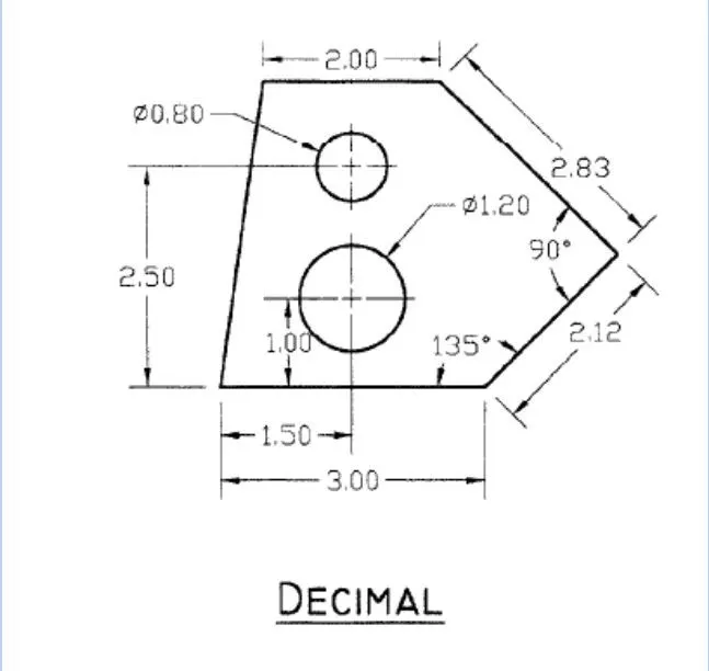
Procedure -
Type L in the command line and press Enter.
Specify the start point: 1,1
Specify next point: @3, 0
Specify next point:@2.12<45
Specify next point:@2.83<135
Specify next point:@-2,0
Specify next point:@0,-2.5
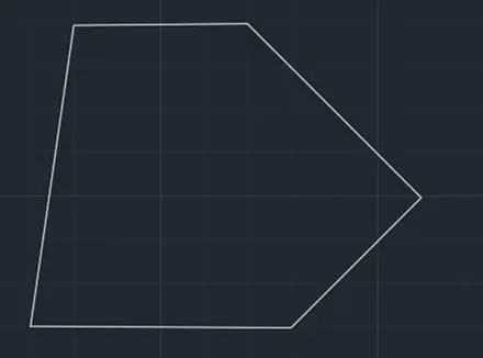
Type L in the command line and press Enter.
Specify the start point: a
Specify next point: @1.5, 0
Specify next point:@0, 1
Specify next point:@0, 1.5
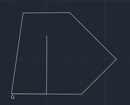
Type C and press enter
Specify centre point of circle: c
Specify radius of circle: .60
Type C and press enter
Specify centre point of circle: d
Specify radius of circle: .40
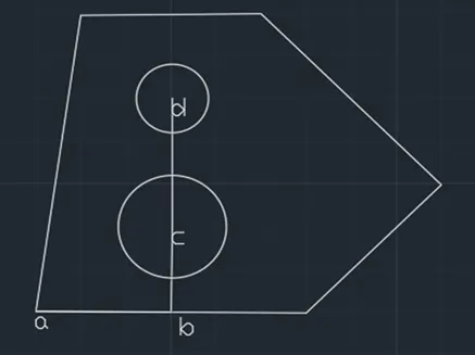
After drawing circle delete the lines ab, bc and cd
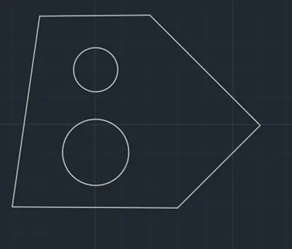
Type DLI or DIMLINEAR on the command line and press Enter.
Give the dimensions as per the drawing.
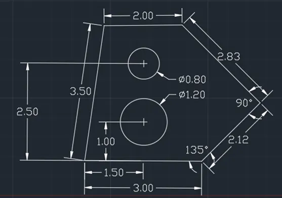
Result - The geometry using decimal units is completed
Q2.
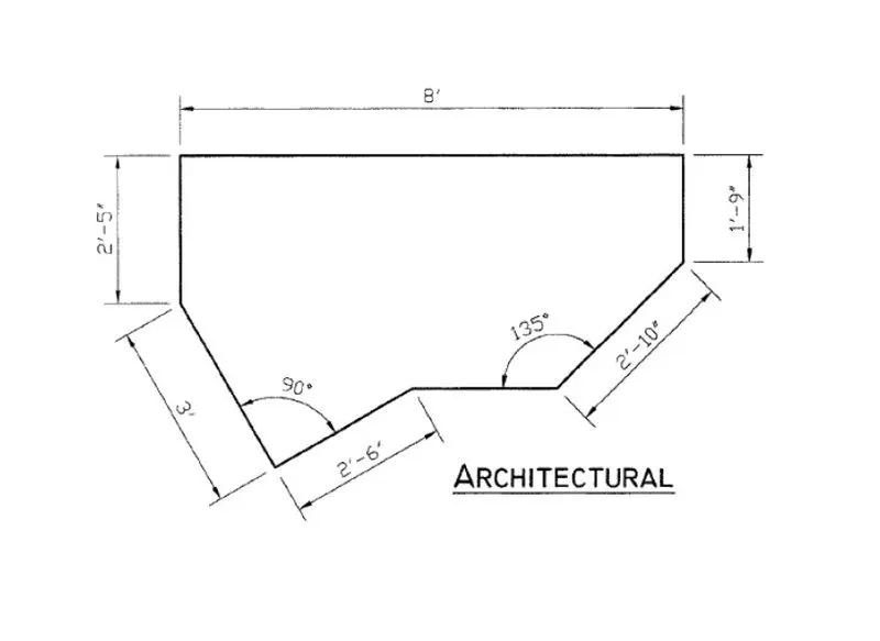
Procedure -
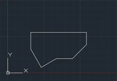
Type L in the command line and press Enter.
Specify the start point 2, 5.
Specify next point: @2’-10<45
Specify next point:@0,1’-9”
Specify next point: @-8’,0
Specify next point:@0,-2’5”
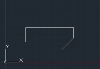
Switch on polar tracking of 30,60, 90
Place the curser at 300 degree tracking and type 3’
Now place the curser at 30 degree and type 2’-6”
Type DLI or DIMLINEAR on the command line and press Enter.
Give the dimensions as per the drawing.
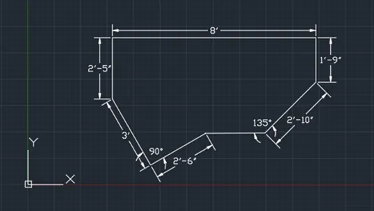
Result - The geometry using architectural units is completed.
Q3.
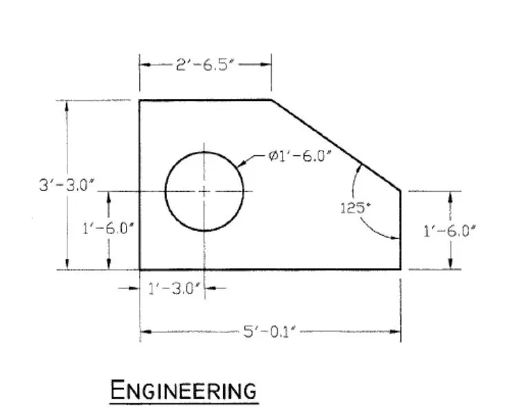
Procedure -
Type Rec or Rectangle in the command line and press Enter.
Specify the first corner of the rectangle.
Enter D for Dimensions.
Enter the length: 5’-0.1”
Enter the width: 3’-3.0”
Specify the other corner.
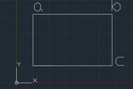
Type CHA or CHAMFER in the command line and press enter
Enter D for Distance
Specify first chamfer distance:2’-3.5”
Specify second chamfer distance:1’-9”
Select the first line ab and second line as bc
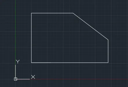
Type L in the command line and press Enter.
Specify the start point d
Specify next point: @1’-3.0”
Specify next point:@1’-6.0”
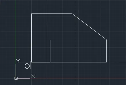
Type C and press enter
Specify centre point of circle: e
Specify diameter of circle: 1’-6.0”
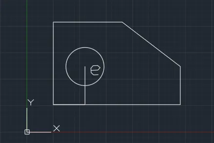
Delete the unwanted lines
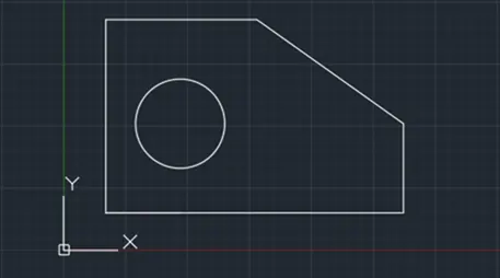
Type DLI or DIMLINEAR on the command line and press Enter.
Give the dimensions as per the drawing.
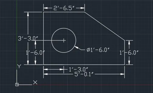
Result - The geometry using engineering units is completed.
Q4.
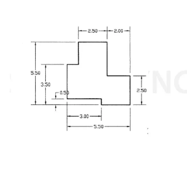
Procedure -
Type L in the command line and press Enter.
Specify the start point 1,1
Specify next point: @3, 0
Specify next point:@0, -.5
Specify next point:@2.5, 0
Specify next point:@0, 2.5
Specify next point:@-2, 0
Specify next point:@0, 3
Specify next point:@-2.5, 0
Specify next point:@0, -2.5
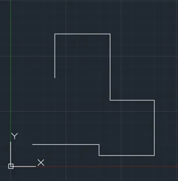
Type L in the command line and press Enter.
Specify the start point a
Specify next point: @0, 3
Specify next point: @1, 0
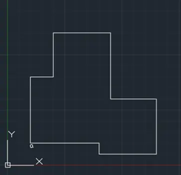
Type DLI or DIMLINEAR on the command line and press Enter.
Give the dimensions as per the drawing.
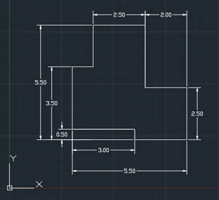
Result - The geometry using decimal units is completed
Q5.
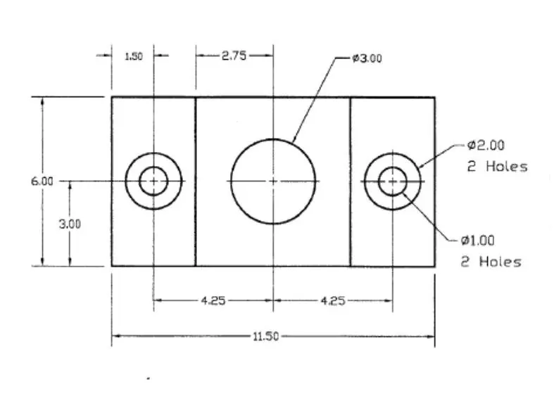
Procedure -
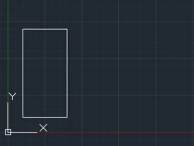
Type Rec or Rectangle in the command line and press Enter.
Specify the first corner of the rectangle.
Enter D for Dimensions.
Enter the length: 3
Enter the width: 6
Specify the other corner.
Type L in the command line and press Enter.
Specify the start point a
Specify next point: @1.5, 0
Specify next point: @0, 6
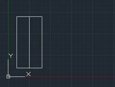
Turn on midpoint in object snap
Type C and press enter
Specify centre point of circle:
Specify radius of circle: .5
Type O or offset on the command line and press Enter.
Specify the value of offset distance:.5
Select the circle to offset and click outside the circle
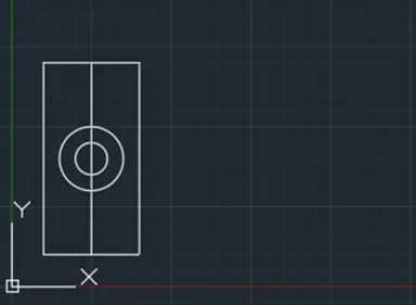
Type Rec or Rectangle in the command line and press Enter.
Specify the first corner of the rectangle.
Enter D for Dimensions.
Enter the length: 5.5
Enter the width: 6
Specify the other corner.
Trim and erase the unwanted lines
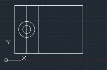
Type CO and press enter
Select the rectangle abcd and click D for displacement and type @8.5, 0
Specify the base point as a and click enter
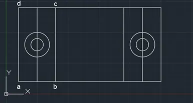
Trim and erase the unwanted lines
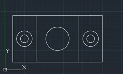
Type DLI or DIMLINEAR on the command line and press Enter.
Give the dimensions as per the drawing.
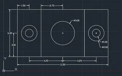
Result - The geometry using decimal units is completed
Q6.
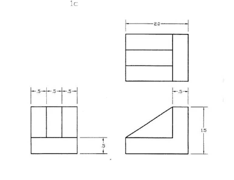
Procedure -
Type Rec or Rectangle in the command line and press Enter.
Specify the first corner of the rectangle as E.
Enter D for Dimensions.
Enter the length: 1.5
Enter the width: .5
Specify the other corner.
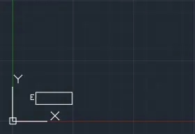
Type Rec or Rectangle in the command line and press Enter.
Specify the first corner of the rectangle as E.
Enter D for Dimensions.
Enter the length: .5
Enter the width: 1.5
Specify the other corner.
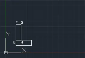
Type CO and press enter
Select the rectangle EFGH and click D for displacement and type @0, .5
Specify the base point as B and click enter
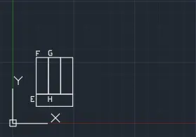
Type L in the command line and press Enter.
Specify the start point E
Specify next point: @0, -.5
Specify next point: @1.5, 0
Specify next point: @0, 1.5
Specify next point: @-.5, 0
Specify next point: @0, -1
Specify next point: @-1, 0
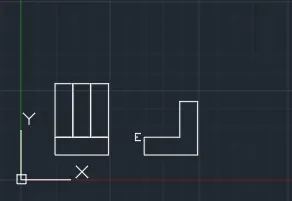
Type L in the command line and press Enter.
Specify the start point E
Specify next point: F
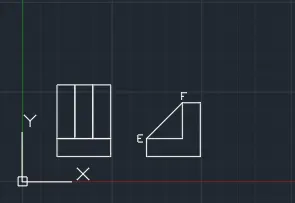
Type Rec or Rectangle in the command line and press Enter.
Specify the first corner of the rectangle as B.
Enter D for Dimensions.
Enter the length: .5
Enter the width: 1.5
Specify the other corner.
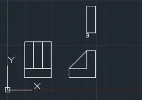
Type Rec or Rectangle in the command line and press Enter.
Specify the first corner of the rectangle as B.
Enter D for Dimensions.
Enter the length: 1.5
Enter the width: .5
Specify the other corner.
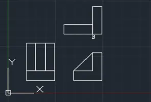
Type CO and press enter
Select the rectangle ABCD and click D for displacement and type @0, .5
Specify the base point as B and click enter
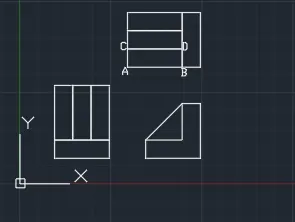
Type DLI or DIMLINEAR on the command line and press Enter.
Give the dimensions as per the drawing.
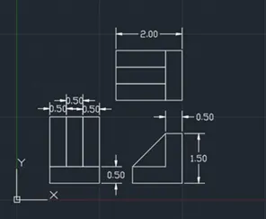
Result - The geometry using decimal units is completed
Q7.
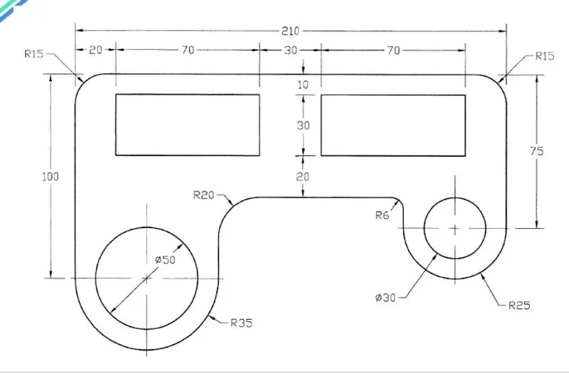
Procedure -
Type L in the command line and press Enter.
Specify the start point L.
Specify next point:@0, -100
Specify next point:@210, 0
Specify next point:@0, 75
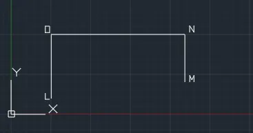
Type F and press enter
Select the first line LO
Specify radius as 15
Select the second line as ON and press enter
Type F and press enter
Select the first line MN
Specify radius as 15
Select the second line as MN and press enter
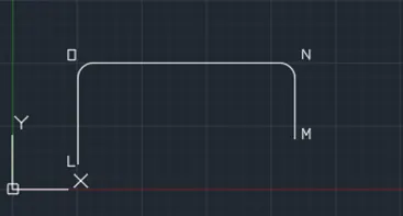
Type L in the command line and press Enter.
Specify the start point L.
Specify next point:@70, 0
Type L in the command line and press Enter.
Specify the start point M.
Specify next point:@-50, 0
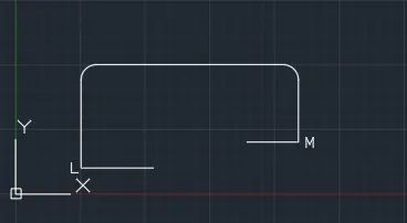
Type C and press enter
Specify centre point of circle: k
Specify radius of circle: 25
Type C and press enter
Specify centre point of circle: j
Specify radius of circle: 15
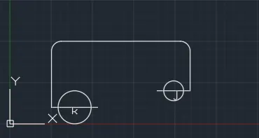
From draw panel select start end radius option from arc menu
Specify start point as g
Specify end point as h
Radius of arc as 35
From draw panel select start end radius option from arc menu
Specify start point as i
Specify end point as h
Radius of arc as 25
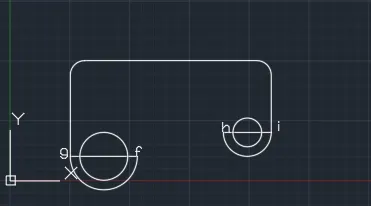
Trim of the lines fg and hi
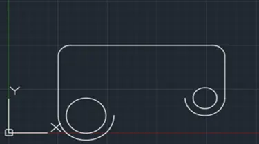
Type Rec or Rectangle in the command line and press Enter.
Specify the first corner of the rectangle.
Enter D for Dimensions.
Enter the length: 70
Enter the width: 30
Specify the other corner.
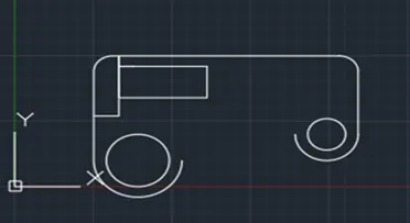
Type CO and press enter
Select the rectangle and click D for displacement and type @100,0
Specify the base point and click enter
Using trim command erase of unwanted lines
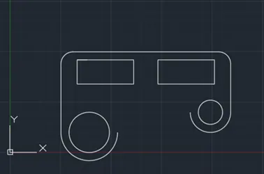
Type L in the command line and press Enter.
Specify the start point e.
Specify next point:0,20
Now draw a line perpendicular to the above line and draw lines starting from a and d respectively
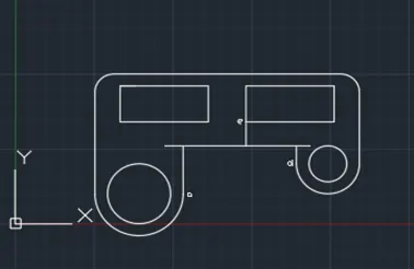
Trim off and erase the unwanted lines.
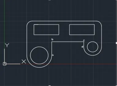
Type F and press enter
Select the first line ab
Specify radius as 20
Select the second line as bc and press enter
Type F and press enter
Select the first line cd
Specify radius as 20
Select the second line as bc and press enter
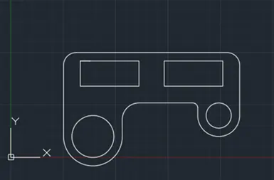
Type DLI or DIMLINEAR on the command line and press Enter.
Give the dimensions as per the drawing.
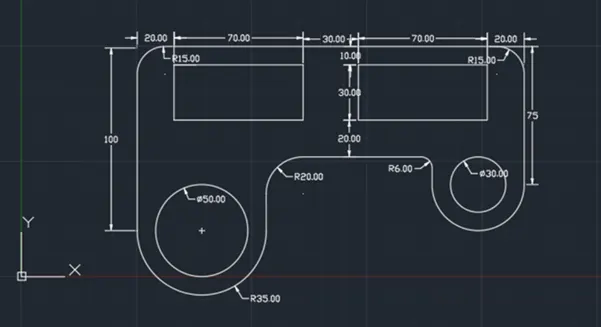
Result - The geometry using decimal units is completed
Q8.
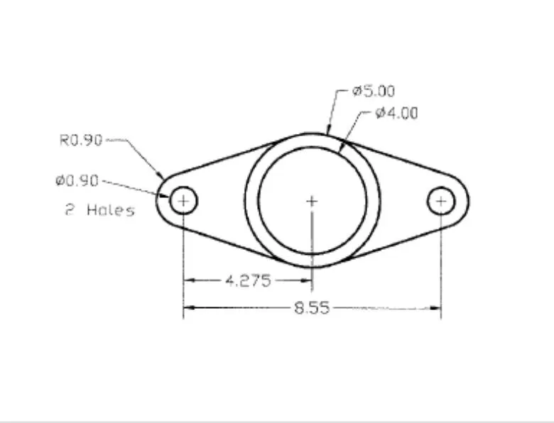
Procedure -
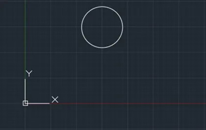
Type C and press enter
Specify centre point of circle: 5, 5
Specify radius of circle: 2
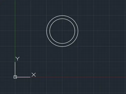
Type O or offset on the command line and press Enter.
Specify the value of offset distance:.5
Select the object to offset and click outside of the circle
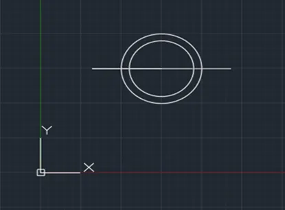
Type L in the command line and press Enter.
Specify the start point 5, 5.
Specify next point:@8.55,0
Type O or offset on the command line and press Enter.
Specify the value of offset distance:.9
Select the object to offset and click on top and bottom
Close the figure with two lines on both the sides
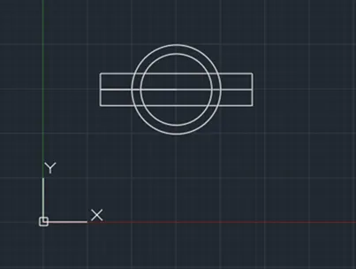
Trim and erase the top and bottom line
Type C and press enter
Specify centre point of circle: a
Specify radius of circle: .45
Type C and press enter
Specify centre point of circle: b
Specify radius of circle: .45
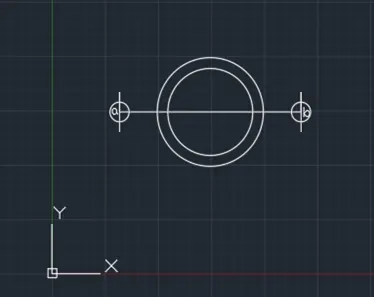
From draw panel select start end radius option from arc menu
Specify start point as c
Specify end point as d
Radius of arc as .90
From draw panel select start end radius option from arc menu
Specify start point as e
Specify end point as f
Radius of arc as .90
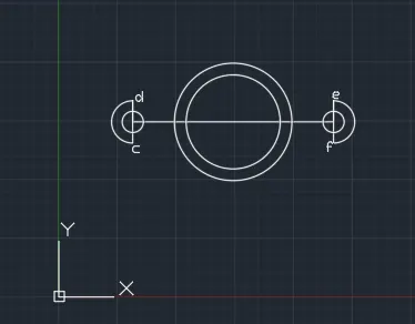
In object snap turn on the tangent
Draw line starting from e to the tangent at the top of big circle
Draw line starting from f to the tangent at the bottom of big circle
Draw line starting from d to the tangent at the top of big circle
Draw line starting from c to the tangent at the bottom of big circle
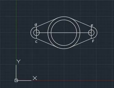
Trim of the unwanted lines to get the geometry
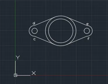
Type DLI or DIMLINEAR on the command line and press Enter.
Give the dimensions as per the drawing.
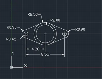
Result - The geometry using decimal units is completed
Q9.
Procedure -
Type L in the command line and press Enter.
Specify the start point 5’, 5’.
Specify next point:@32’-6”, 0
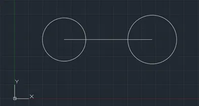
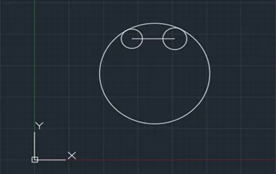
Type C and press enter
Specify centre point of circle: 5’ ,5’
Specify radius of circle: 8’
Type C and press enter
Specify centre point of circle: 5’ ,5’
Specify radius of circle: 9’
Type C and press enter
Select tan, tan, rad
Select first tangent by clicking on top tangent of left circle
Select second tangent by clicking on top tangent of right circle
Specify radius as 41’-8”
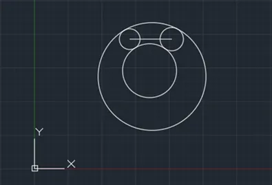
Type C and press enter
Select tan, tan, rad
Select first tangent by clicking on bottom tangent of left circle
Select second tangent by clicking on bottom tangent of right circle
Specify radius as 20’-10”
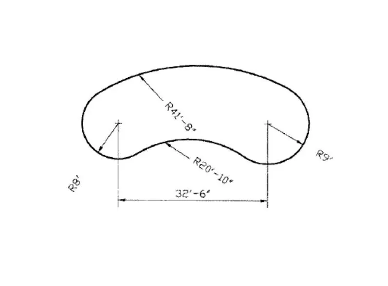
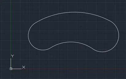
Trim and erase the unwanted parts to get the geometry
Type DLI or DIMLINEAR on the command line and press Enter.
Give the dimensions as per the drawing.
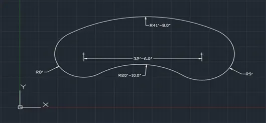
Result - The geometry using engineering units is completed
Q10.
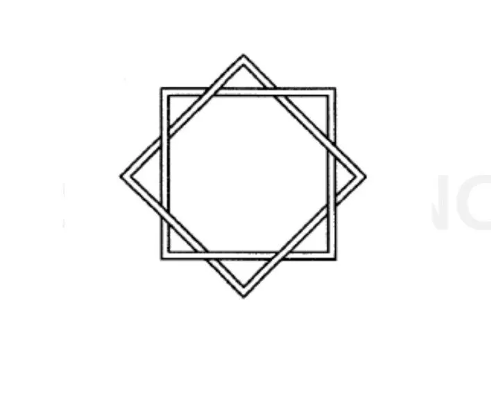
Procedure -
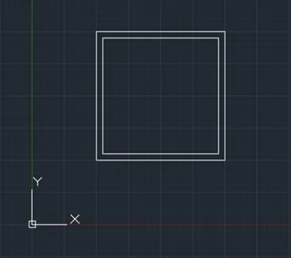
Type Rec or Rectangle in the command line and press Enter.
Specify the first corner of the rectangle.
Enter D for Dimensions.
Enter the length: 10
Enter the width: 10
Specify the other corner.
Type O or offset on the command line and press Enter.
Specify the value of offset distance:.5
Select the object to offset and click inside the rectangle
Type RO and press Enter
Select the object: rectangle
And rotate it by 45 degree by selecting a base point.
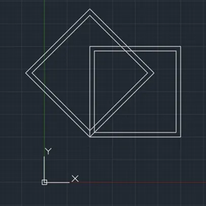
Move the rotated rectangle and place it at the centre.
Trim of the additional lines
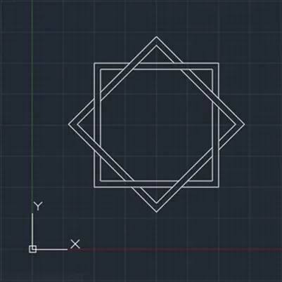
Result - The geometry using decimal units is completed.
Q11.
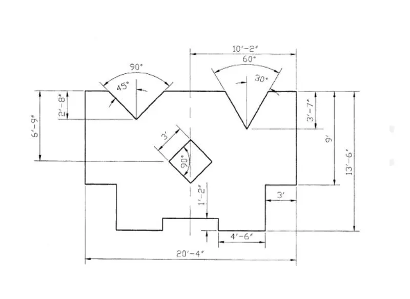
Procedure -
Type L in the command line and press Enter.
Specify the start point g.
Specify next point: @2’-6”, 0
Specify next point:@0, -1’-2”
Specify next point:@4’-6”, 0
Specify next point:@0, 4’-6”
Specify next point:@3’, 0
Specify next point:@0, 9’
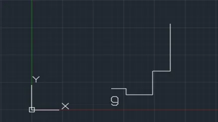
Type MI and press enter
Select the mirror objects.
Specify the first point of the mirror as g
Specify the second point at the top
At Erase source object type N.
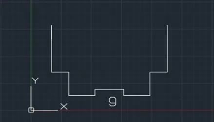
Type L in the command line and press Enter.
Specify the start point e.
Specify next point: @0, -3’-7”
Specify next point:@-8’-7”, 0
Turn on the polar tracking for 30,60,90 degree
With d as centre draw a line at an angle of 30 degrees till it touches the bottom line and 120 degrees towards up and close the figure at f
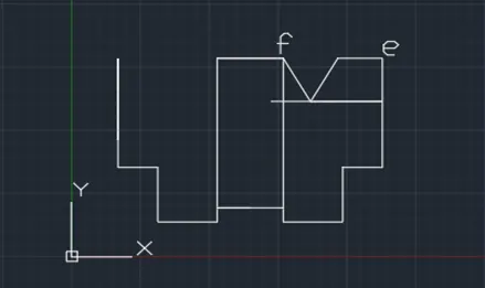
Type L in the command line and press Enter.
Specify the start point c.
Specify next point: @0, -2’-8”
Specify next point:@6’-7”, 0
Turn on the polar tracking for 45,90,135 degree
With d as centre draw a line at an angle of 45 degrees till it touches the line and 135 degrees towards up and close the figure at c
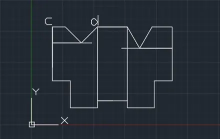
Delete the unnecessary lines.
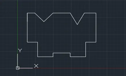
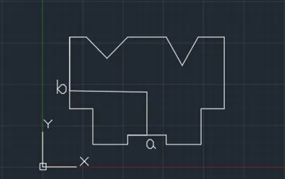
Draw a line from b and a so that they will intersect at the centre.
Point b is at a distance of 6’-9’ from the top and point a is at the centre of the baseline.
Type Rec or Rectangle in the command line and press Enter.
Specify the first corner of the rectangle.
Enter D for Dimensions.
Enter the length: 3’
Enter the width: 3’
Specify the other corner.
Type RO and press Enter
Select the object: rectangle
And rotate it by 45 degrees by selecting a base point.
Also, draw a line as diagonal to the rectangle
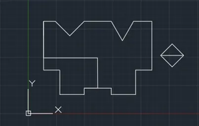
Place the rectangle created in the correct place using the diagonal line
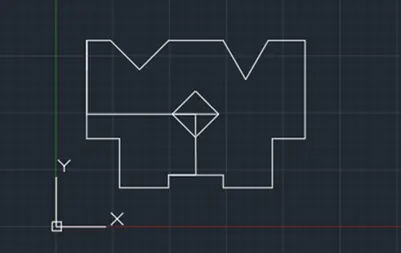
Delete or trim off the unwanted lines to get the final geometry
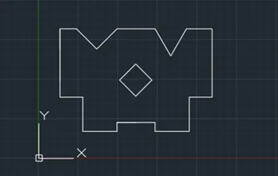
Type DLI or DIMLINEAR on the command line and press Enter.
Give the dimensions as per the drawing.
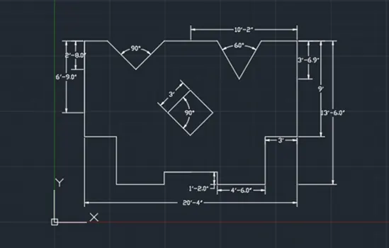
Result - The geometry using engineering units is completed