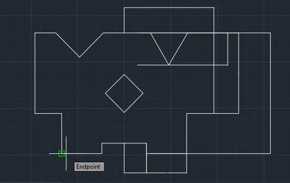
Drafting of various geometries using Chamfer, Fillet tool in AutoCad
1.
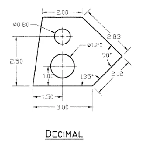
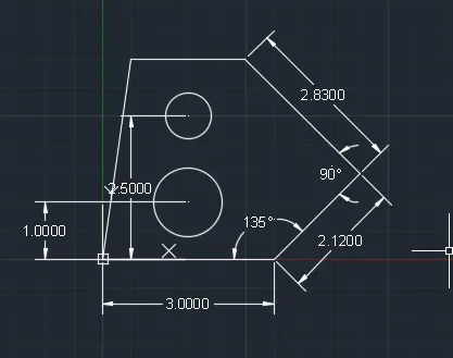
Aim: to draw the above figure.
Procedure:
1. Draw line of 3 units.
2. Drawing line of 2.12 units at an angle of 135 degree
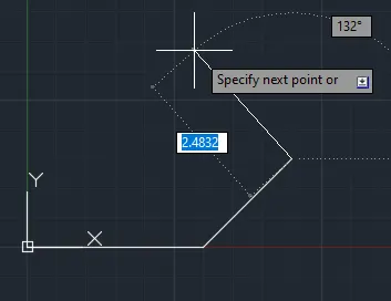
3. Drawing line of 2.83 units at an angle of 90 degree
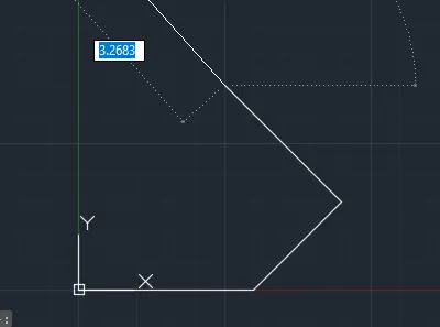
4. Drawing a perpendicular line and thren closing the shape, the outer geometry is completed.
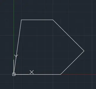
5. Drawing a line from the midpoint of the bottom line.
6. Drawing two offsets at 1 unit and 2.5 unit from the bottom line.
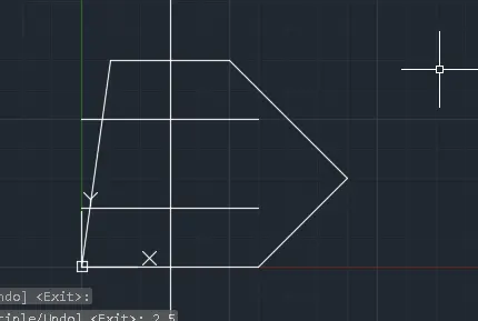
7. The intersection of the first offset and the vertical line is the centre for the circle1
8. Drawing a circle of diameter 1.2
9. The intersection of the second offset and the vertical line is the centre for the circle 2
10. Drawing second circle of diameter 0.80
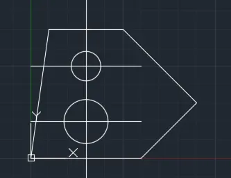
11. Triming the vertical line and the offsets (as they were drawn for reference)
12. giving dimenssions.
2.
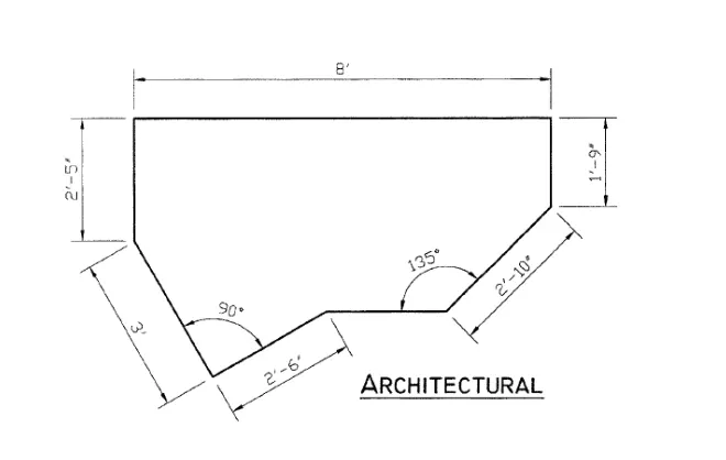
Aim: To draw the above given figure.
Procedure:
1. Drawing a horizontal li ne of 8'
2. Drawing a vertical line of 1'-9" from the end point of line 1
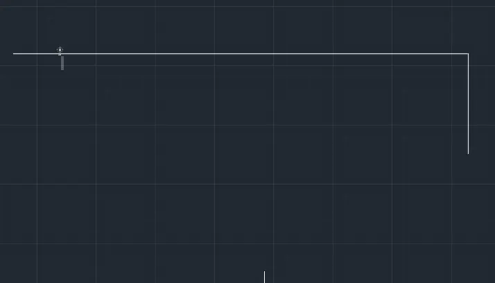
3. seperately drawing a line and another line of 2'-10" at an angle of 135 degree from that line.
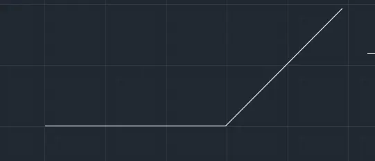
4. Seperately drawing another line of 3' and a connected line of 2'6" at an angle of 90 degree.
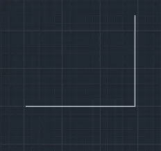
5. drawing a line of 2'-5" from the first line of 8'
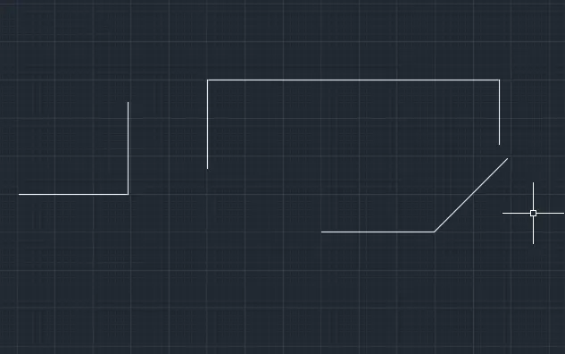
6 now joining all the components.
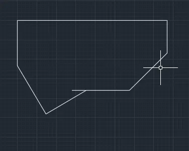
7. trimming the additional line.
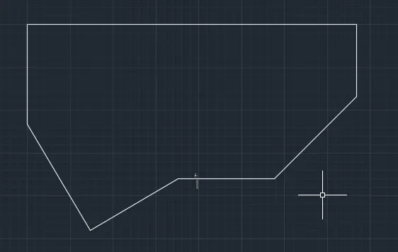
8. Mentioning the dimensions.
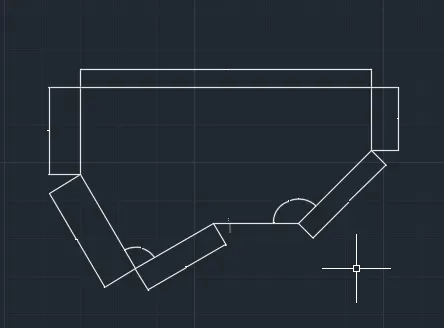
3.
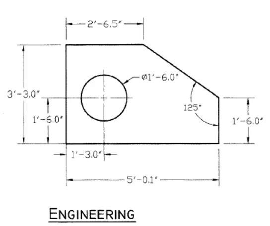
Aim: To draw the above shown figure.
Procedure:
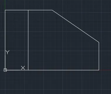
1. Draw a horizontal line of 5'-01" from point (0,0) and a vertical line of 1'-6" from the end point.
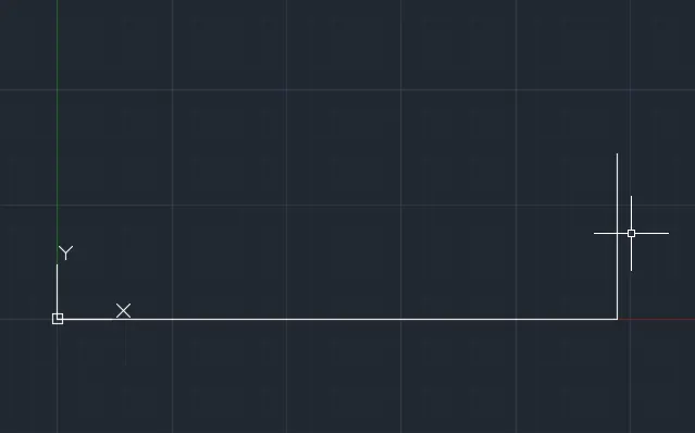
2. From the start point (0,0) draw another verticl line of 3'-3"
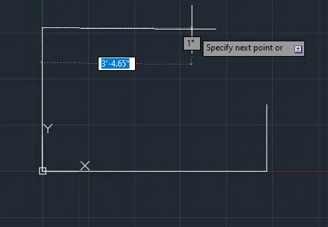
3. a horizontal line of 2'-6.5" from the end
4. joining the two ends
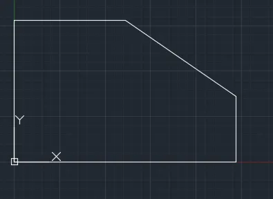
5. Taking offset from the left line at a distance of 1'-3"
6. Drawing another offset from the bottom at 1'-6.0"
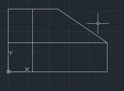
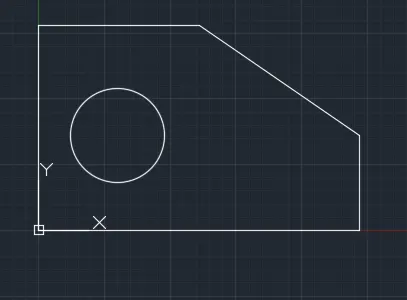
7. Drawing a circle with diameter 1'-6.0" considering the intersection of the two offsets as the centre.
8. Triming the offsets.
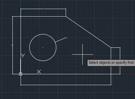
9. mentioning the dimenssions
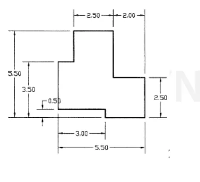
4. Aim: to draw the figure below
procedure:
1. Draw a base line of 2.5 units, and a vertical line of 2.5 units from the end.
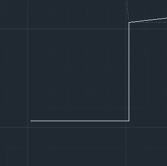
2. continuing with a line of (-2) units that is 2 units in the reverse direction.
3. draw a line of 3 units in the upwards direction.
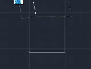
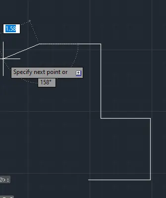
4. Drawing a line of 2.5 units in the reverse direction
5. Drawing a line of 2 units in the downward direction
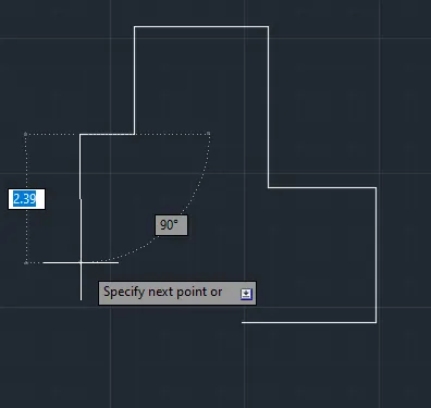
6. Drawing a horizontal line of 1 unit in the reverse direction and 3 units in the downward direction.
7. Drawing a line of 3 units towards the right, and closing the figure.
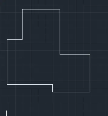
8. Mentioning dimenssions.
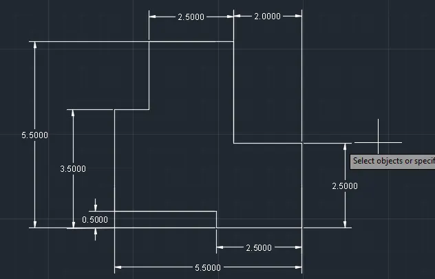
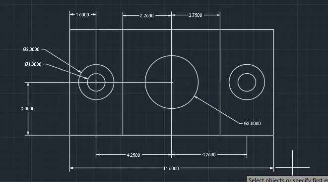
5. Aim: To draw the below given figure:
Procedure:
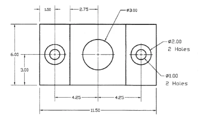
1. Draw a rectange with length as 11.50 units and breadth as 6 units.
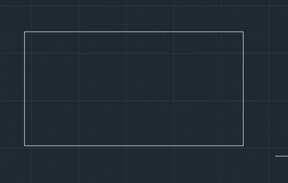
2. taking the midpoint of the base and drawing a vertical line through it.
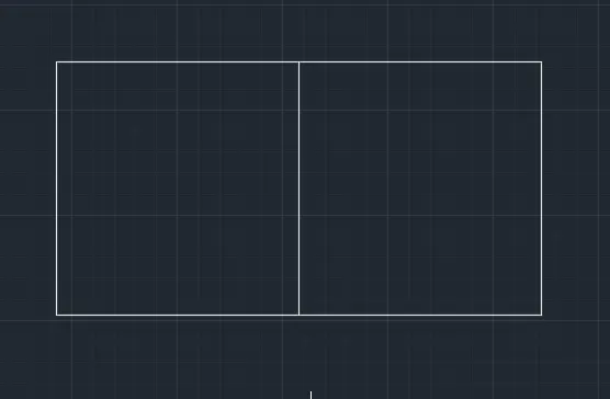
3. Drawing offset at 2.75 unit on both side of the centre line.
4. Drawing offset at 4.25 unit on both sides of the centre line.
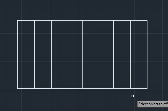
5. Drawing a line bisecting the midpoints of the breadths.
6. The intersection points are the centres of the circles.
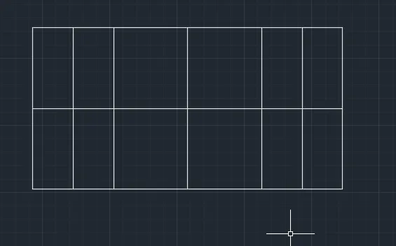
7. Drawing the circles
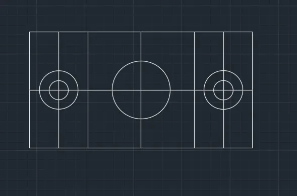
8. Trimming the reference lines and mentioning dimensions.
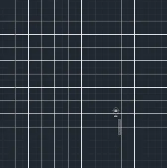
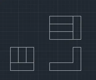
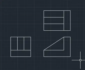
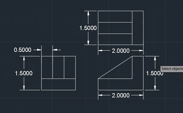
6. To draw the below shown figure:
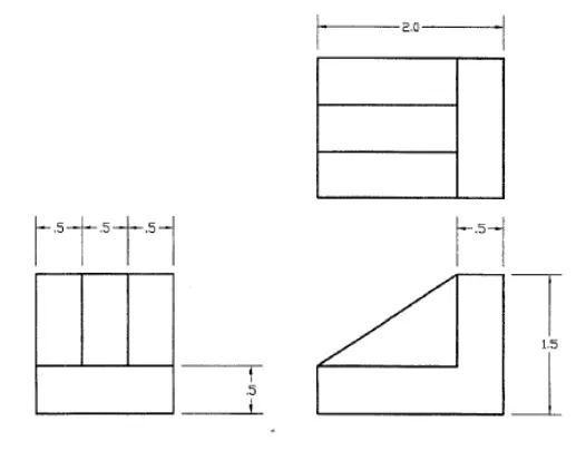
procedure:
1. Drawing vertical and horizontal xlines
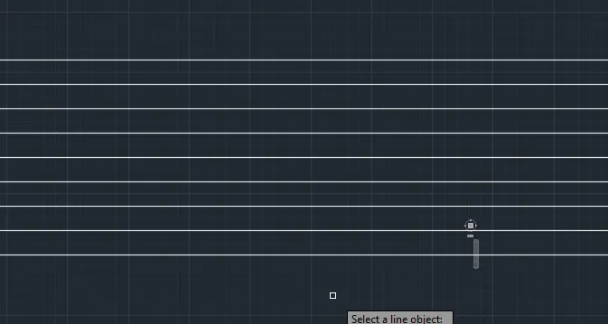
2. Using Trim option
3. mentioning the dimenssions
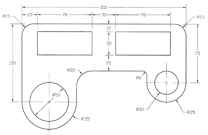
7.Aim : To draw the below shown figure.
Procedure:
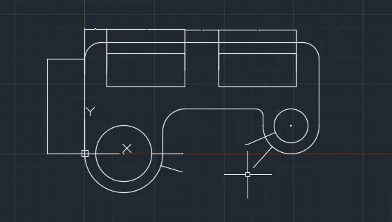
1. Starting from pt (0,0) draw a line of 00 units in Y direction (0,100) from there draw a line of 210 unit in the x direction (210,0).
2. From this point drawing a line of 75 unit in -y direction( 0, -75)
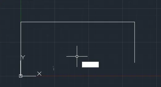
3. Filleting the first edge useing radius as 15 units.
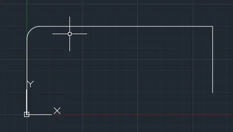
4. Filleting the second edge uswing radius as 15 units.
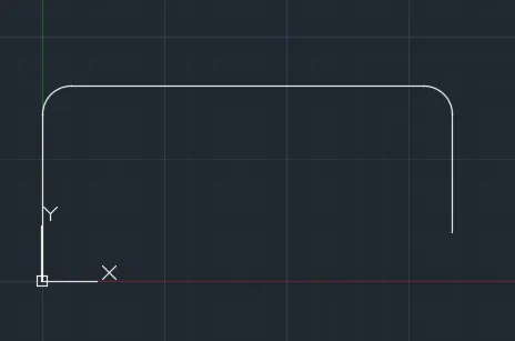
5. From the start point (0,0) drawing a horizontal line of 70 units in the x direction (70,0), continuing with a line of 40 units in the y direction (0,40), from here drawing a vertical line of 90 units in the x direction (90,0).
6. Drawing a vertical line of 15 units in the -y direction, and closing the geometry.
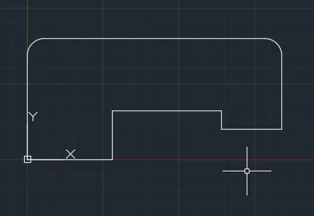
7. From the midpoint of the first baseline drawing 2 circles of diameter 50 and radius 35.
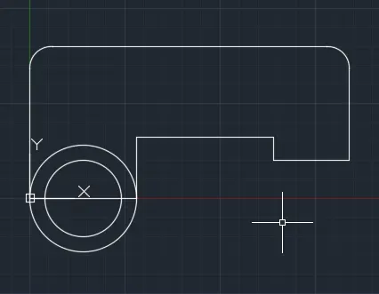
8. From the midpoint of the second baseline drawing 2 circles of diameter 30 and radius 25.
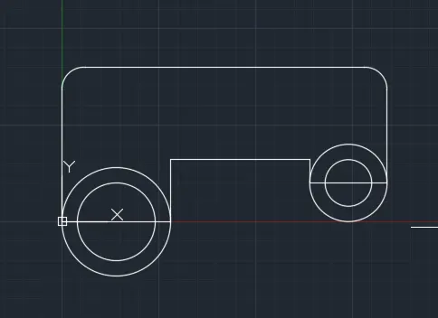
9. Filleting the first internal edge with radius 20.
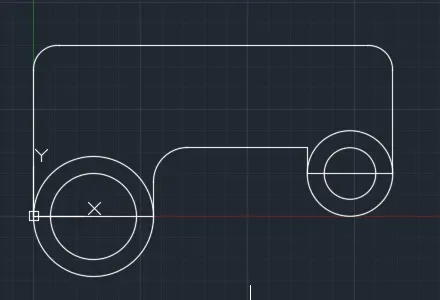
10. Filleting the second internal edge with radius 6.
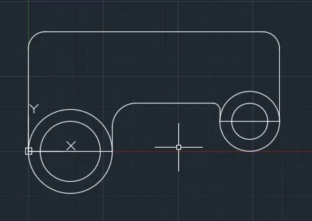
11. Triming the extra halves of the circles and he baselines.
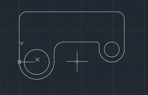
12. offsets from the first line at 20 units and the top line at 40 units. The intersection of these offsets is the start point of the first rectangle.
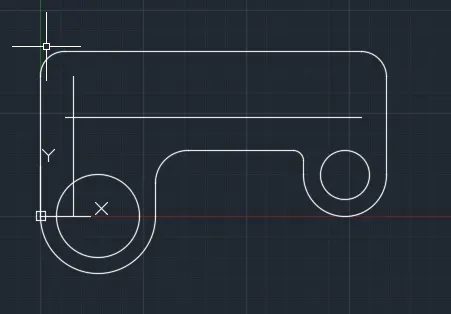
13. Drawing a rectangle from the intersection of offsets with length 70 amd breadth 30. Makin a copy and moving it to the appropriate distance for the second rectangle.
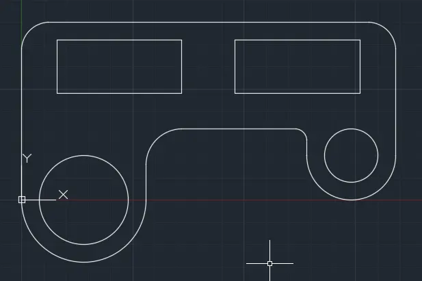
14. Mentioning dimensions.
8. Aim: To draw the below shown figure.
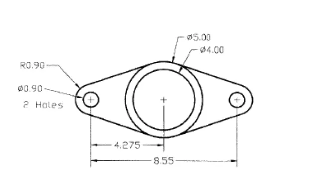
Procedure:
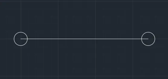
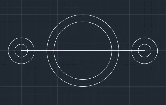
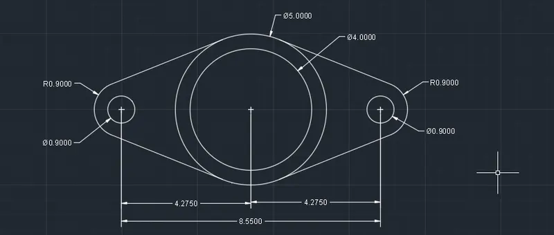
1. Draw a line of 8.55 units
2. Drawing circles of diameter 0.9 units on both the ends.
3. From the midpoint of the line drawing 2 circles of diameter 4 units and 5 units respectively.
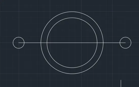
4. Drawing circles of radius 0.9 units at the end points of the line
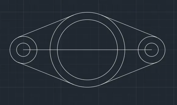
5. Drawing tangents from circle of radius 0.9 unit to the circle of diameter 5 units. (used line option with transperent command of tangent. )
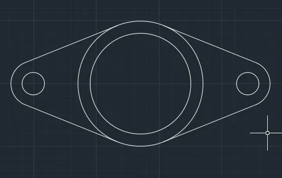
6. Using trim option on both the corner circles and th reference baseline.
7. Mentioning the dimensions
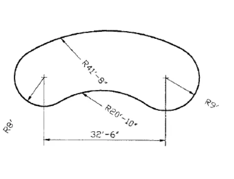
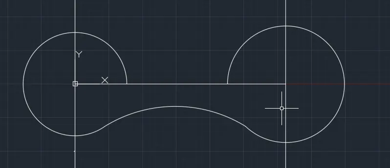
9. Aim : To draw the below shown figure.
procedure:
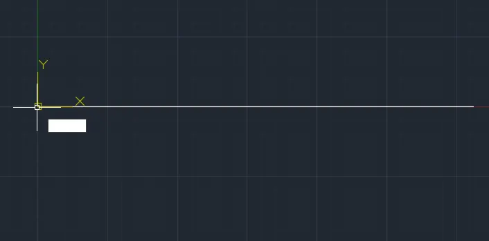
1. Drawing a baseline of 32'-6"
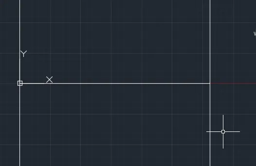
2. Drawing two vertical xlines at the ends
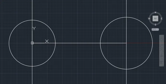
3. At the endpoints of our baseline drwing two circles one of radius 8' and the other of radius 9'
4. Taking the intersection of the circle(R9) and the Xline as start point and intersection of circle (R8) and the X line as the end point drawing an arc of radius 20'- 10"
Triming the circle part
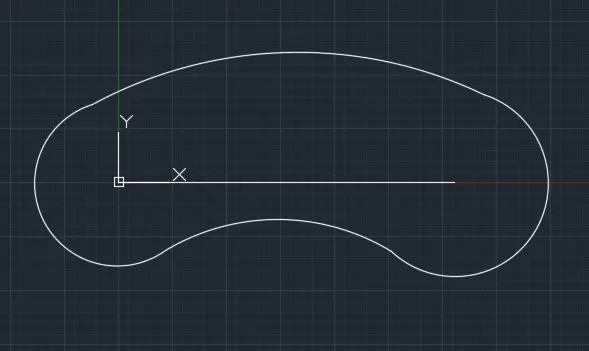
5. Similarly taking the intersection of the circle(R9) and the Xline as start point and intersection of circle (R8) and the X line as the end point drawing an arc of radius 41'- 8" .
Triming the circle additional part and the reference baseline
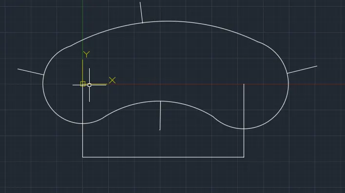
Mentioning the dimensions.
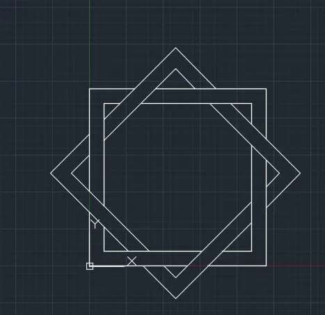
10. Aim: To draw the below shown figure:
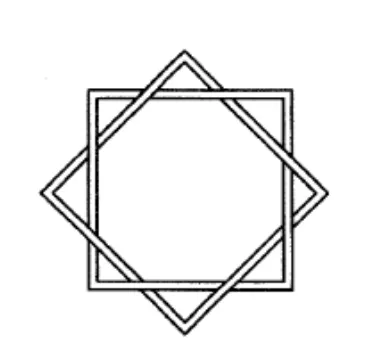
Procedure:
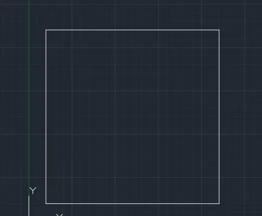
1. Drawing a square
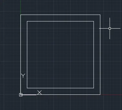
2. Taking offset of the polygon.
3. Rotating a copy by 45 degree
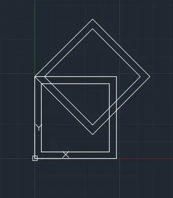
4. moving the rotated copy.
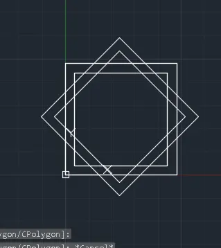
5. Triming the overlaping lines
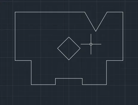
11. Aim : To draw the below shown figure
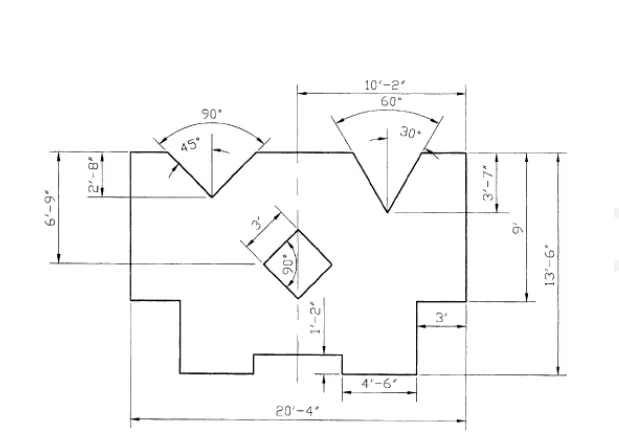
Procedure:
1. starting with a vertical Xline.
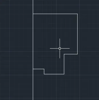
2. Drawing line in X direction (2'-6",0) continuing to 1'2" in y direction, 4'-6" in x direction, 4'-6" in y direction, 3' in x direction , 9' in Y direction and 10'-2" in negative X direction to get the following geometry.
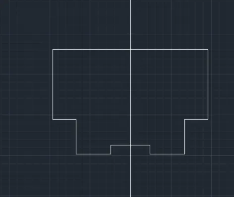
3. Using mirror option to create other part of the geometry.
4. creating a rectangle of length and breadth of 3'
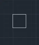
5. Rotaing this rectangle to 45 degree
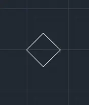
6. marking an offset from the top line at a distance 6'-9", and moving theabove rectangle so the edges co incide with the xline and the offset.
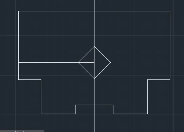
7. Erasing the offset anad the Xline. from the centre of the right top half drawing a line of 3'-7"
8. From the end point marking two lines at 30 degree on either side.
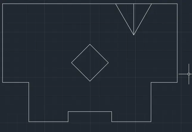
9. Triming the extra lines.
10. from the centre of the left top half marking a reference line of 2'-8". From the end point of this line marking lines at 45 degree on either side.
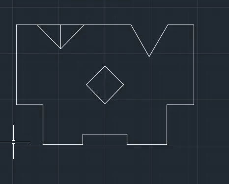
11. erasing the extra lines.
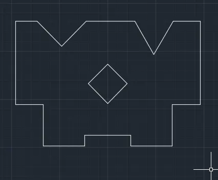
12. mentioning dimensions