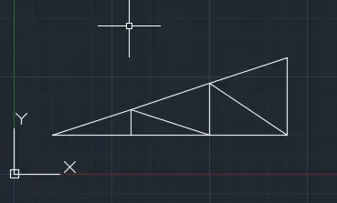
Creation of geometries by Coordinate system methods using AutoCad
1. Sketching Geometeries from P1 using all the co-ordinate system methods.
Aim : Skectching geometeries from P1 using all the co- ordinate system methods.
Introduction: The procedure would involve sketching of geometries using the following methods;
-
Absolute Coordinate system
-
Relative Coordinate system
-
Relative polar coordinate system
-
Direct Distance Entry method
Procedure :
1. Absolute coordinate system
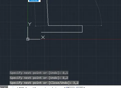
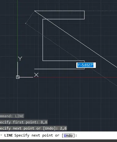
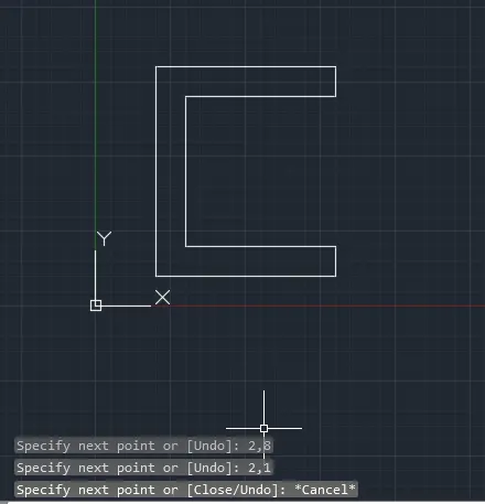
- Using the line tool we mark the first point that is (2,1)
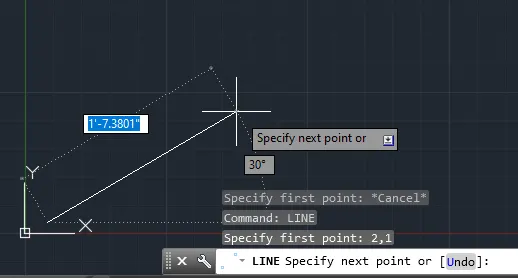
- The next point is 6 units far on the X axis from point A, therfeore the co-ordinates for the next point are (8,1)
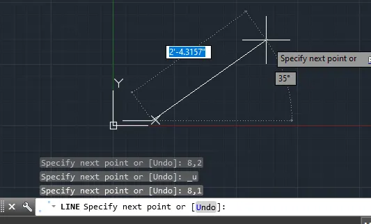
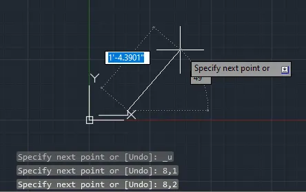
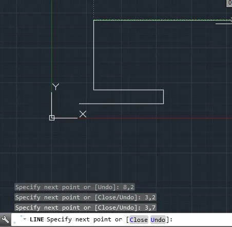
- The third point is 1 unit above the point B, therefore adding 1 in the Y axis making the coordinates for point C as (8,2)
-
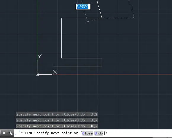
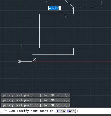
Similarly we will mark the rest of the points to complete P1
2. Relative co-ordinate system
- In case of relative co ordinate system the based on the first point.
We will mark the first point (2,1) using the line tool.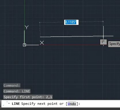
- Now the second point is 6 units further in the X direction and does not have any change along the y direction, therefore dx is equal to 6 and dy is equal to 0.
For marking the second point we will use the character @ along with dx and dy.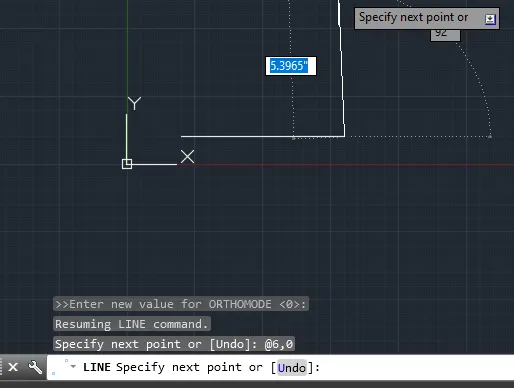
- In case of third point dx is 0 wherein dy is 1.
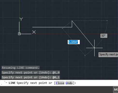
- For point 4 we have to come back 5 units from point 3, therefore dx here is -5, and dy is 0.
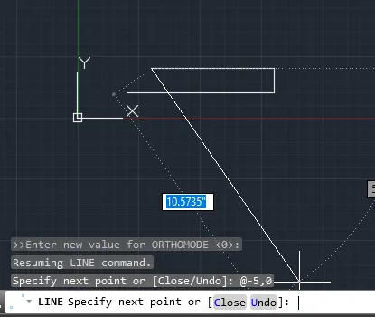
- Similarly marking the rest of the points
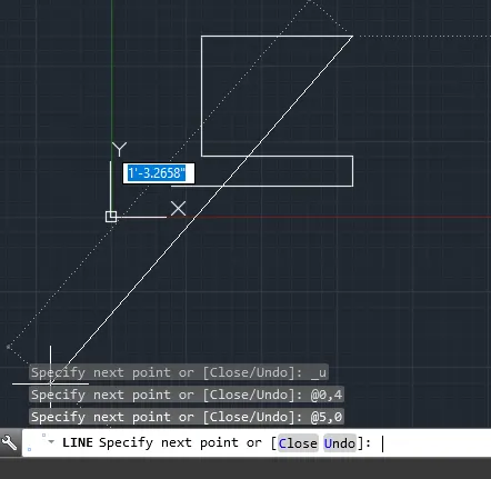
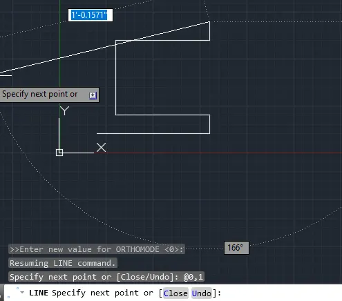
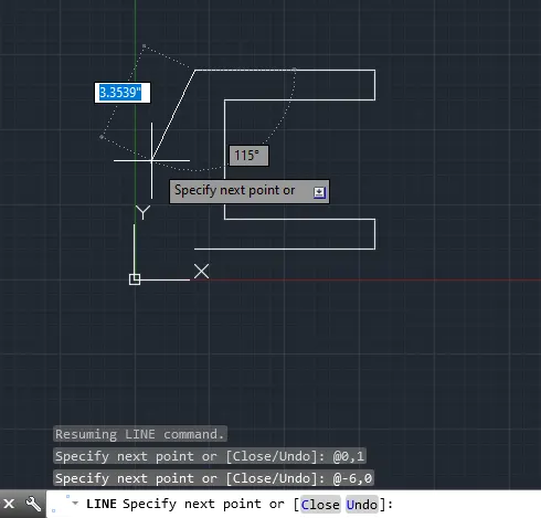
- Finally using the command C to close the geometry.
3. Polar coordinate system
- In case of polar coordinate system we use only the length and the angle.
So we will mark the first point (2,1)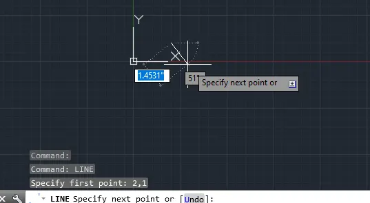
- The length to point 2 is 6 and the angle is 0
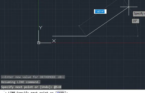
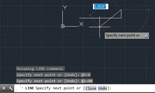
- Point 3 is at a length of 1 unit and an angle of 90 to point 2, therefore we will use (@1,<90)
-
Point 4 is at a length of 5 units and at an angle of 180, therefore we will use (@5,<180)
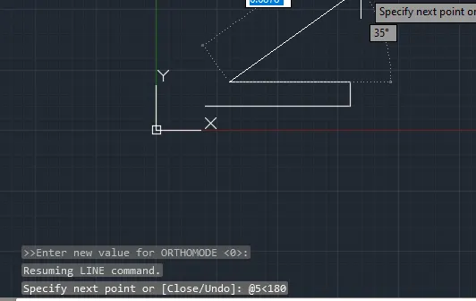
- distance 4 at an angle of 90
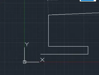
- distance 5 angle 0
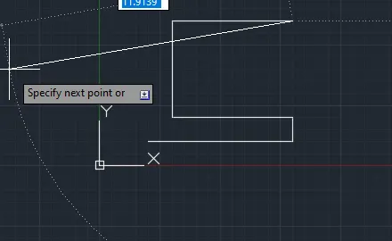
- distance 1 angle 90
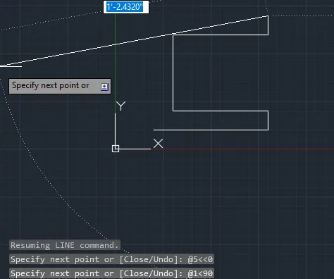
- distance 6 angle 180
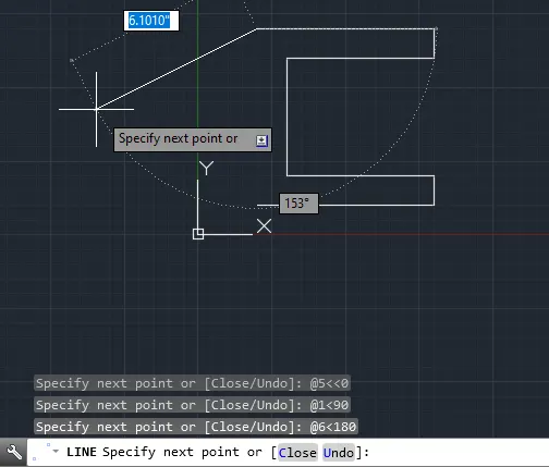
- closing the figure
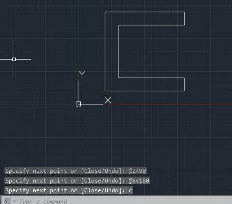
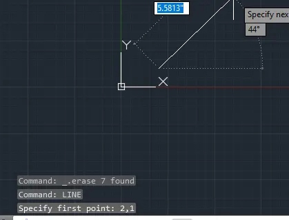
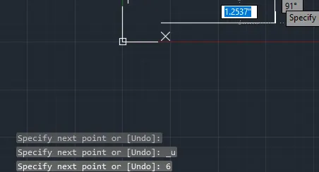
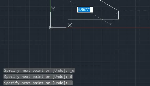
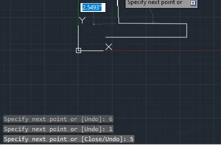
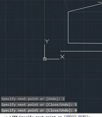
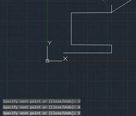
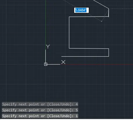
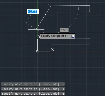
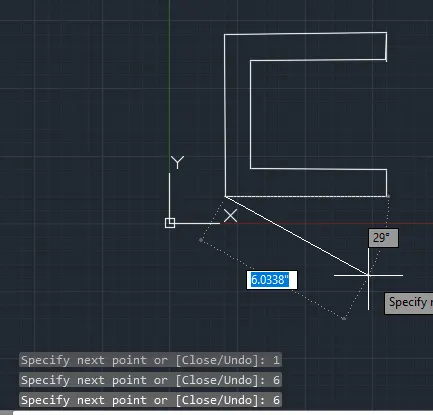
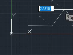
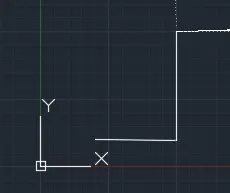
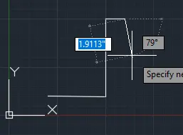
4. In direct distance entry method, we have to point the cursor and enter the distance. So in whichever direction our cursor goes the line will be extended as per the distance we enter.
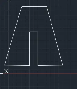
2. Sketching Geometeries from P2 using all the co-ordinate system methods.
Aim : Skectching geometeries from P1 using all the co- ordinate system methods.
Introduction: The procedure would involve sketching of geometries using the following methods;
-
Absolute Coordinate system
-
Relative Coordinate system
-
Relative polar coordinate system
-
Direct Distance Entry method
Procedure :
1. Absolute coordinate system:
- Marking the first point (2,1) using the line tool.
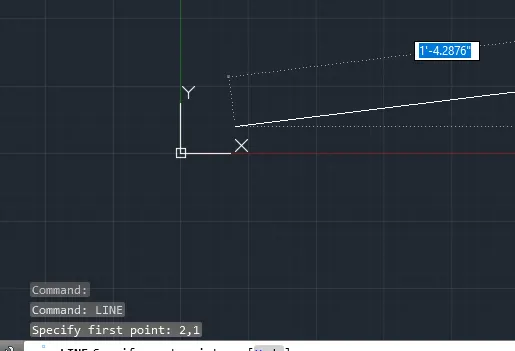
- Second point (5,1)
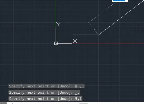
- Third point (5,5)
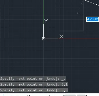
- Fourth point (6,5)
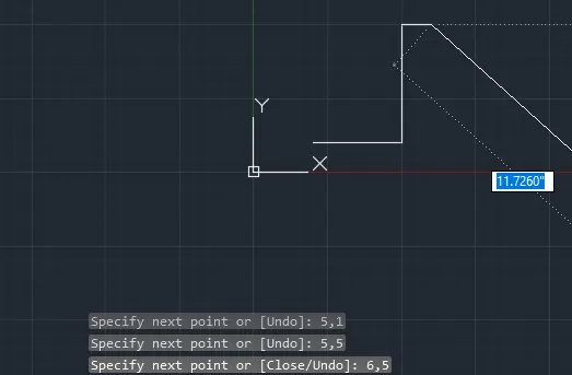
- Fifth point (6,1)
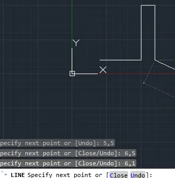
- Sixth point (9,1)
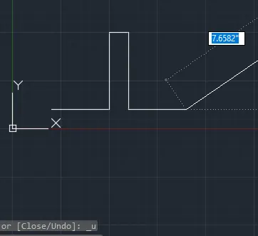
- Seventh point (7,8)
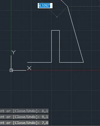
- Eight point (4,8)
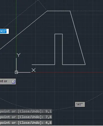
- close.
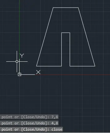
2. Relative coordinate system
- Marking the first point (2,1)
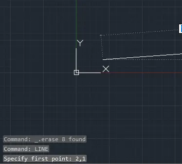
- Second point: dx=3 dy=0
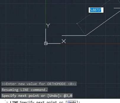
- Third point: dx=0 dy=4
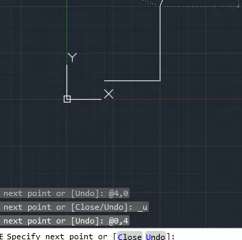
- Fourth point: dx=1 dy=0
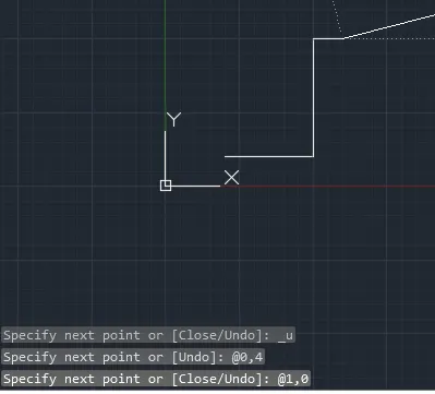
- Fifth point: dx=0 dy=-4
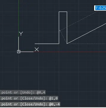
- Sixth point: dx=3 dy=0
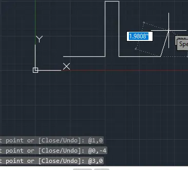
- Seventh point: dx=-2 dy=7
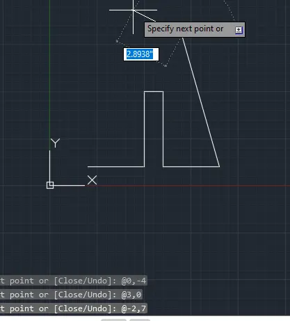
- Eigth point: dx=-3 dy=0
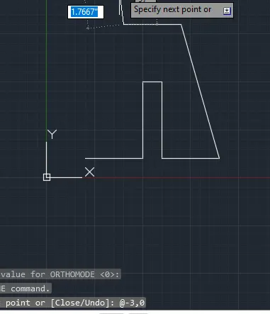
- close
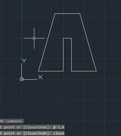
3. Relative polar coordinate system
- Marking the first point (2,1)
- second point: distance 3 angle 0
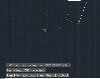
- third point: distance 4 angle 90
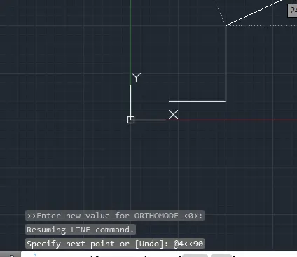
- Fourth point: distance 1 angle 0
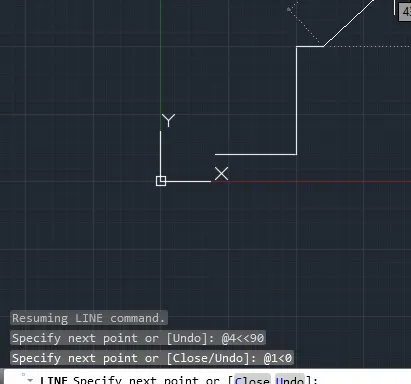
- Fifth point: distance 4 angle 270
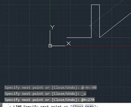
- Sixth point: distance 3 angle 0
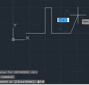
- Seventh point: distance 7.28 angle 105
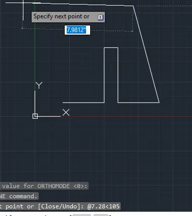
- Eigth point: distance 3 angle 180
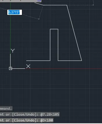
- close
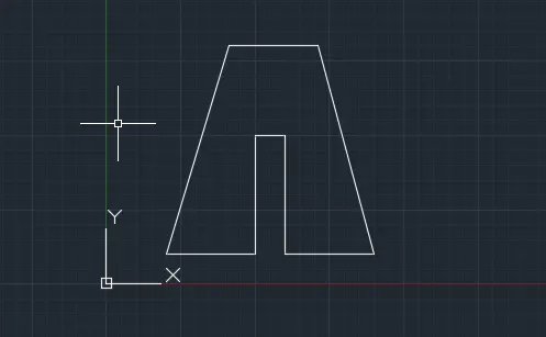
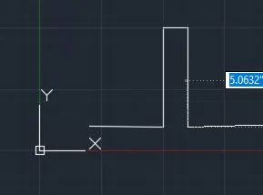
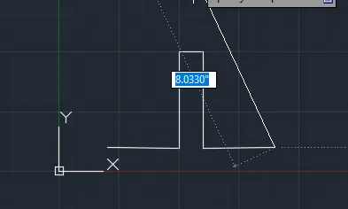
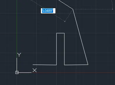
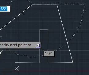
4. Direct Distance Entry method
3. P3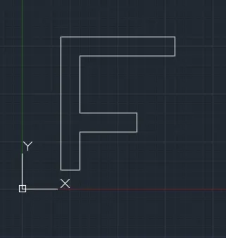
4. P4
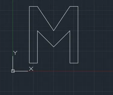
5. P5
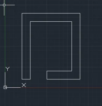
6. P6
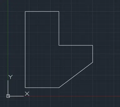
First we will draw the outer shape
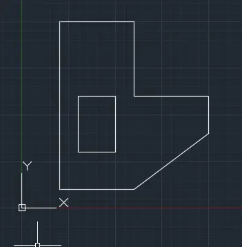
For the internal shape taking the coordinates (3,3) as start point and drawing the rectangle.
7. P7
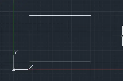
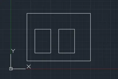
First we will draw the outer rectangle
second we will draw first of the two internal rectangles. We will take start point as (3,2)
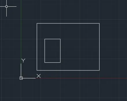
Next we will draw the second rectangle taking the start point as (6,2)
8. P8
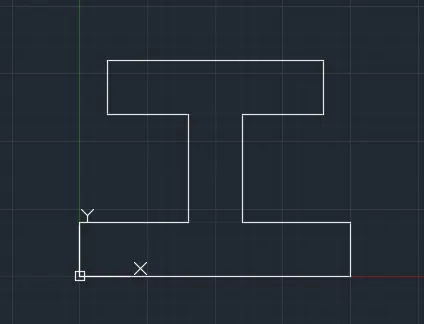
9. P9
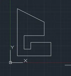
10. P10
First we will draw the external figure.
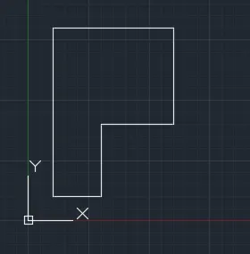
Next we will draw the internal figure taking (2,5) as the start point.
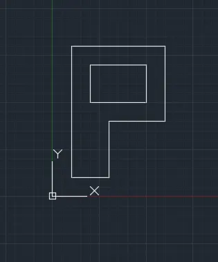
11. Wood profile
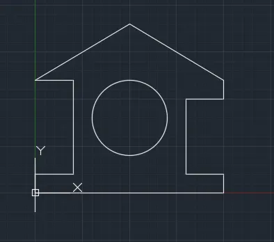
12. Queen post truss
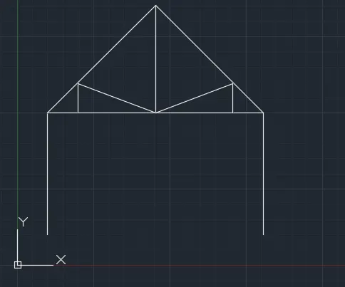
13. Howe truss
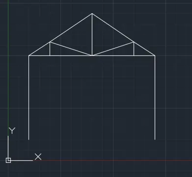
14. Flat truss
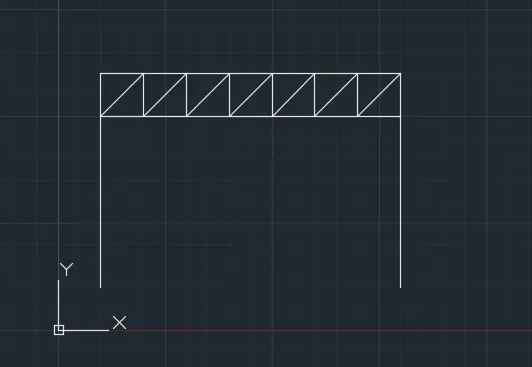
15. Mono Pitch