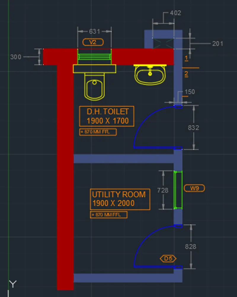
Creating a Residence Layout, Seating plan, Toilet and Utility room plan using AutoCad
Week 4-Assignment 4-Module 2
Aim: To sketch and edit the requested layout using the different drawing, modifying tools with application of Layer command covered in week 4 sessions.
Introduction:
- The topics covered in week 4 (titled Start Advanced Sketching and Editing II and Drawing Aids) which are essentials in plotting the requested geometries are as follows;
- Layers, it the primary method for organizing objects in a drawing by function or purpose. It can reduce the visual complexity of a drawing and improve display performance by hiding information that you don’t need to see at some point. There are many properties under the Layer Tools such as Layer Off/On, Isolate/ Unisolate, Freeze/ Thaw, Lock/ Unlock, Make Current, Match Layer etc. depending on your needs and requirements to the drawings you are going to plot and for presentation purposes. Layer Properties Manager can be can be enabled as below;
- Ribbon : Home>Layers
- Command: LAYER
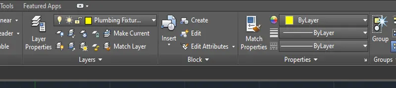
- Drawing a Simple Plan using layer option, a sample drawing was made and presented by applying all the options/ tools applicable to Layers.
Procedure:
A. Starting AutoCAD;
- Search for the AutoCAD icon from your desktop and double click it to make it run or you may search it from windows search tool and open from there if no shortcut in the desktop.
- You may simply click the “Get Started-Start Drawing” icon once the AutoCAD is opened or you may click the Application Menu tab with the “A” AutoCAD logo on the top -left most side of the screen and select new. From the new you may find a variety of templates that suits your requirements.
- For this exercise, we will just simply proceed on Get Started-Start Drawing” icon and set up the measurement units inline with the drawing requirements.
B. Setting the Drawing Parameters;
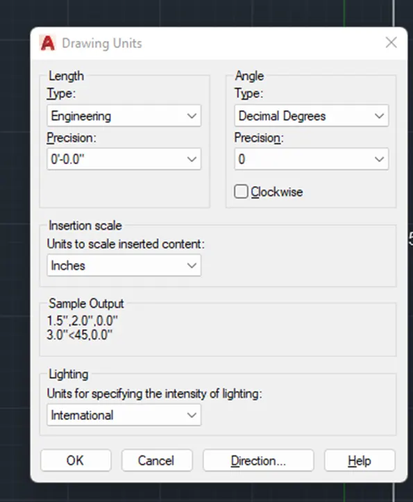
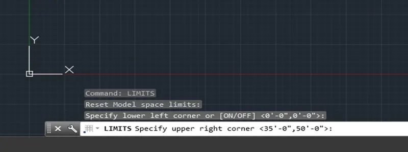
- Set up the measurement units according to sketched information provided.
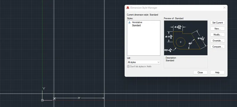
- To set up that, a much faster way is to type “units” in the command line and hit enter or space bar. The Drawing Units Dialog box will then pop up and measurement parameters will then set up in line with the requirements. Similar thing, you need to set up the dimension through the DDIM command.
- As for the gridlines, you may right click gridline icon in the status bar and go for the drafting settings. Under the Snap and Grid of the Drafting Settings Dialog box, you may set up the needed spacing of grids along its X and Y axis. “DS” command will also work to pop up the Drafting Settings Dialog box.
C. Starting the exercise;
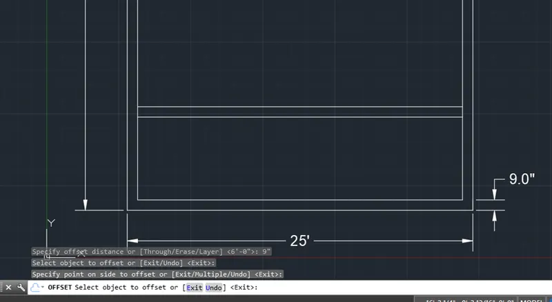
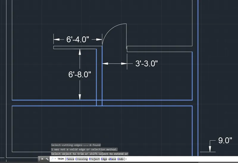
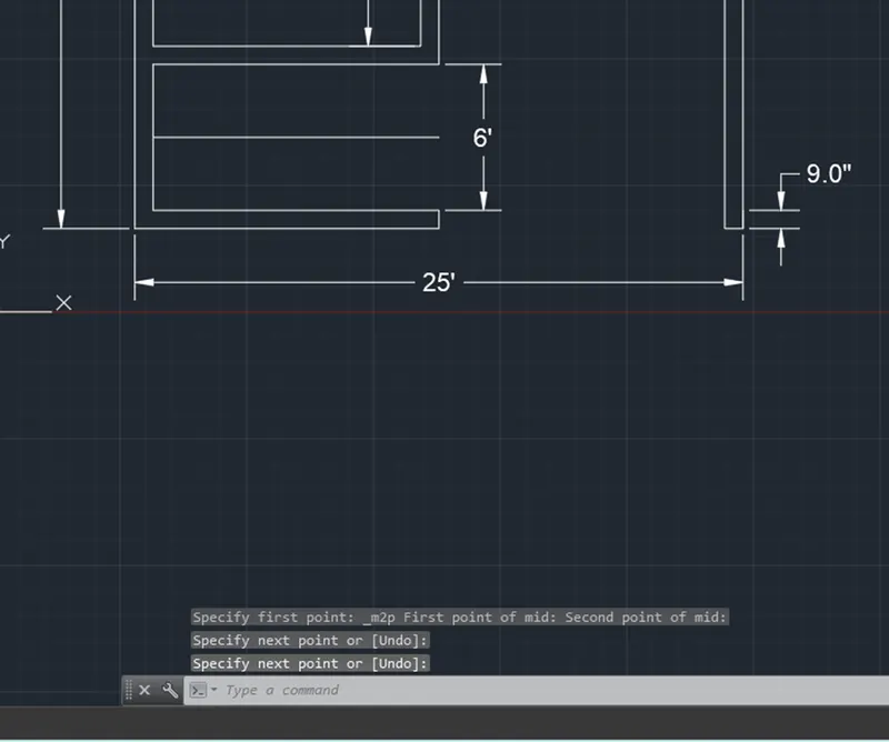
- Combination and manipulation of all the different coordinate entry methods, drawing and modifying tools learned from weeks 1 to 4 were being used here in the completion of all the exercises given and result as pasted below.
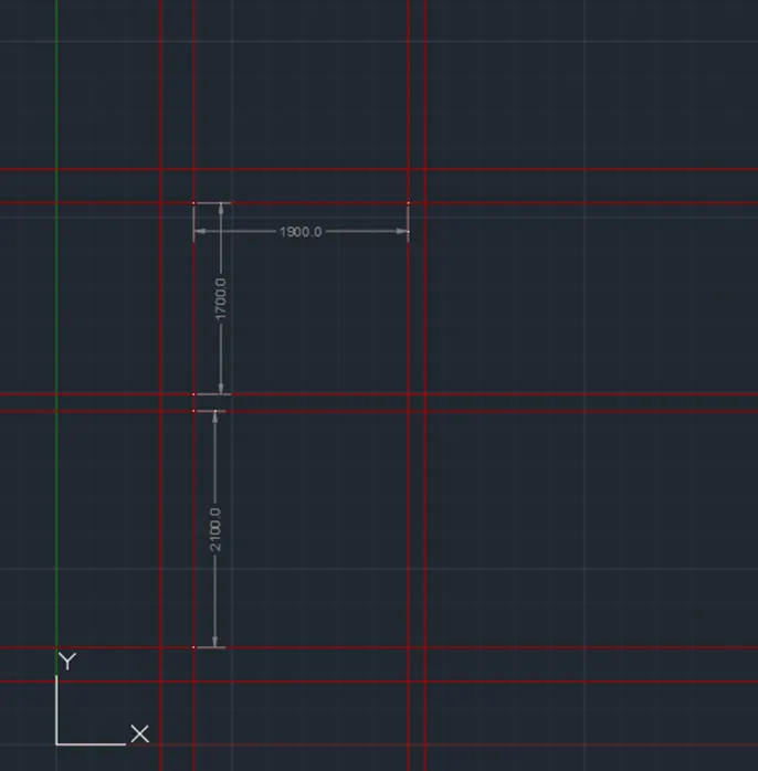
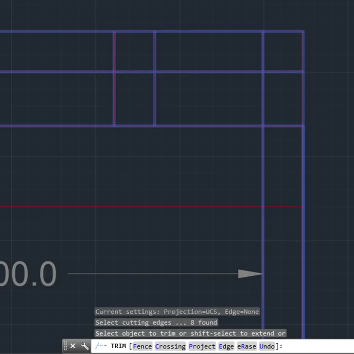
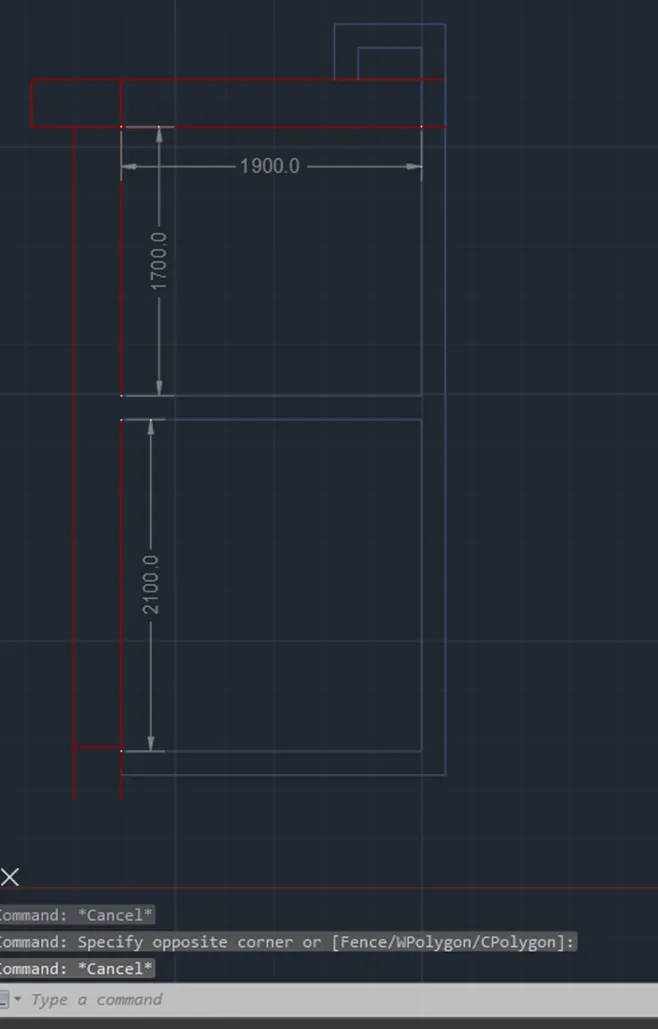
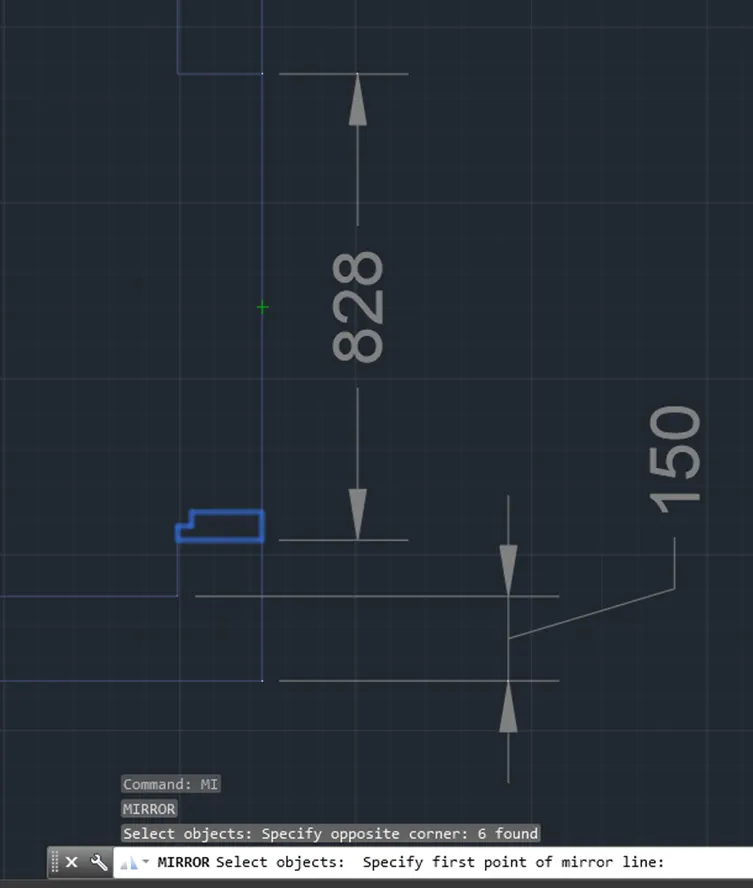
- I have attached some screenshots while plotting the needed three exercises to show the procedure on how it was done to come out with the requested layouts.
D. Challenge;
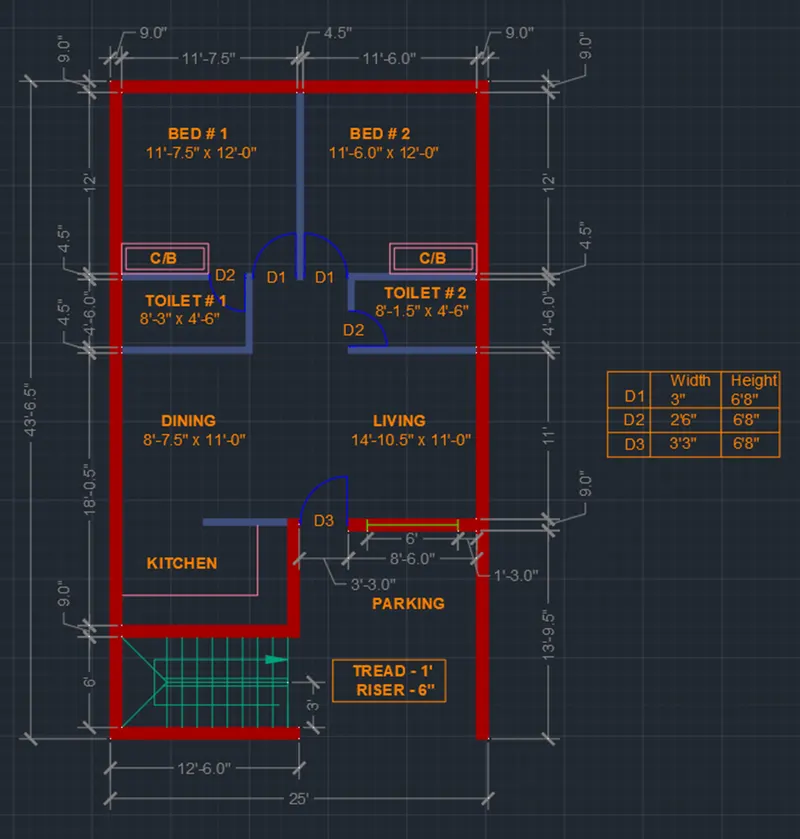
Challenge 1:
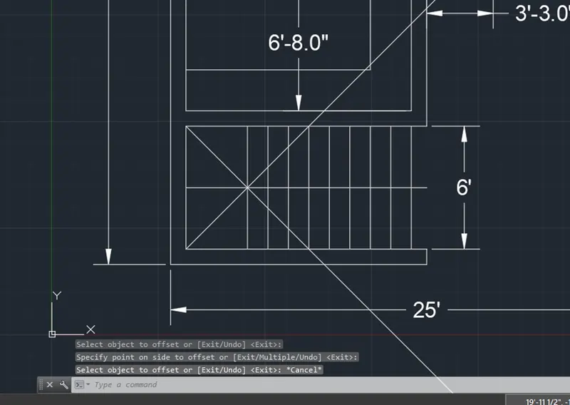
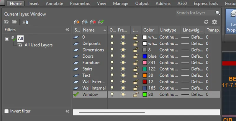
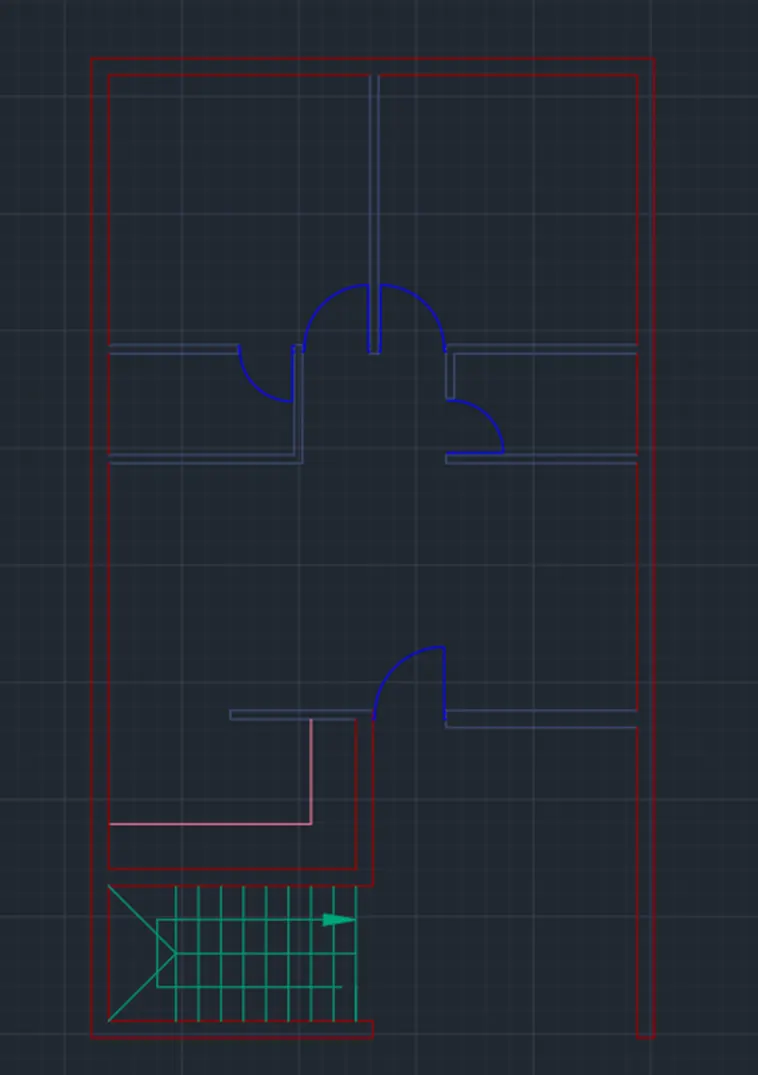
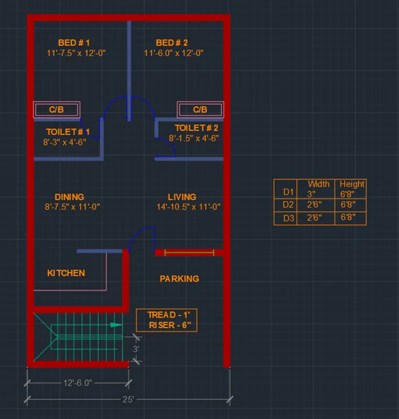
Completed Layout for Challenge 1
Challenge 2:
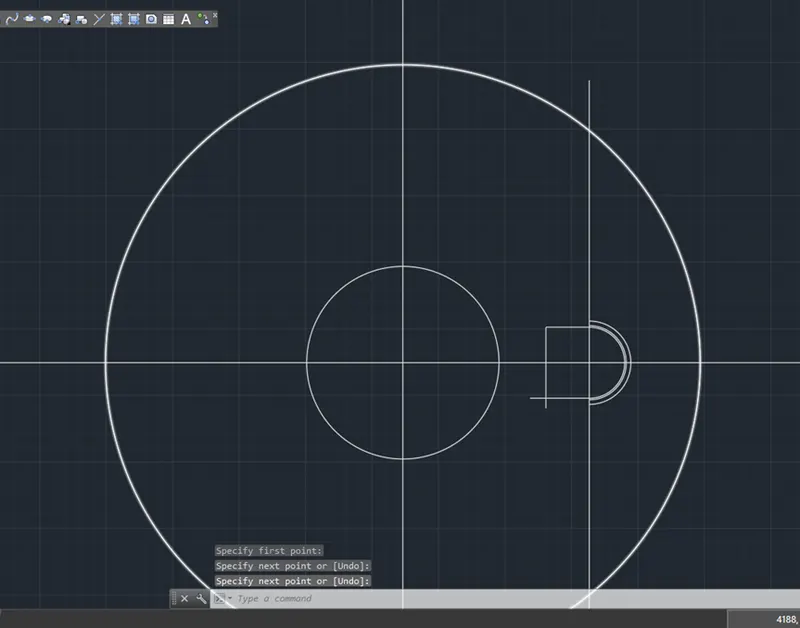
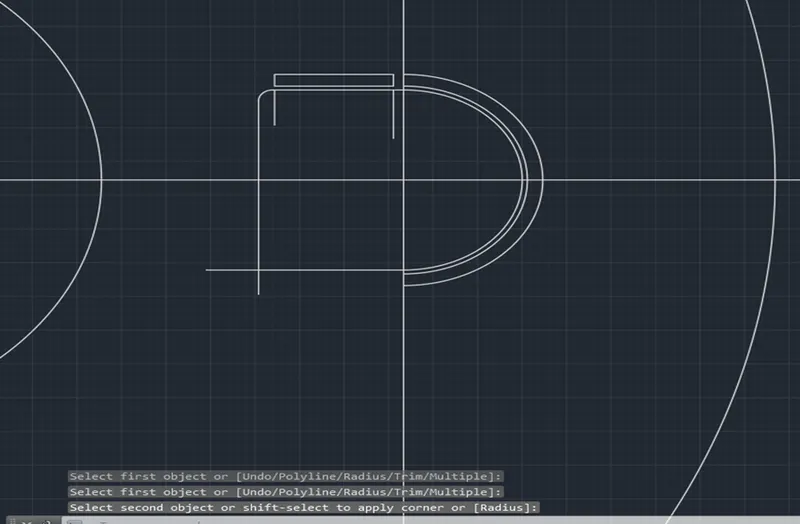
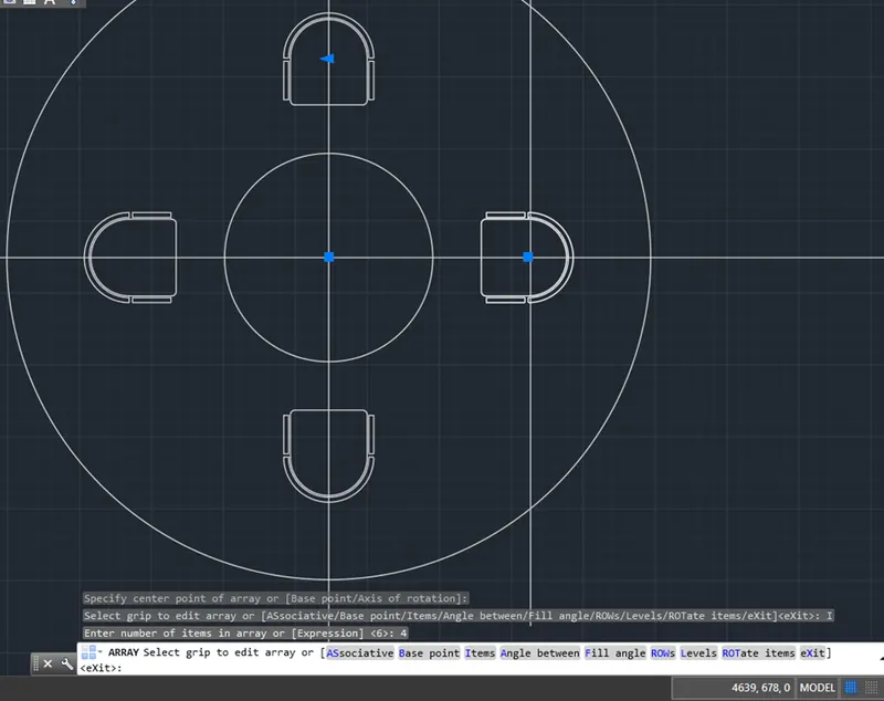
Completed Layout for Challenge 2
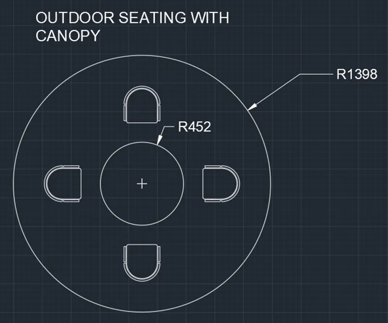
Challenge 3:
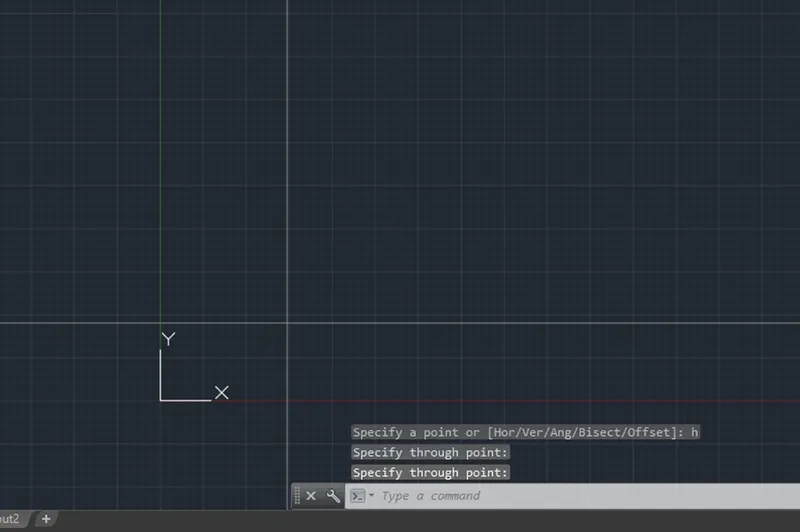
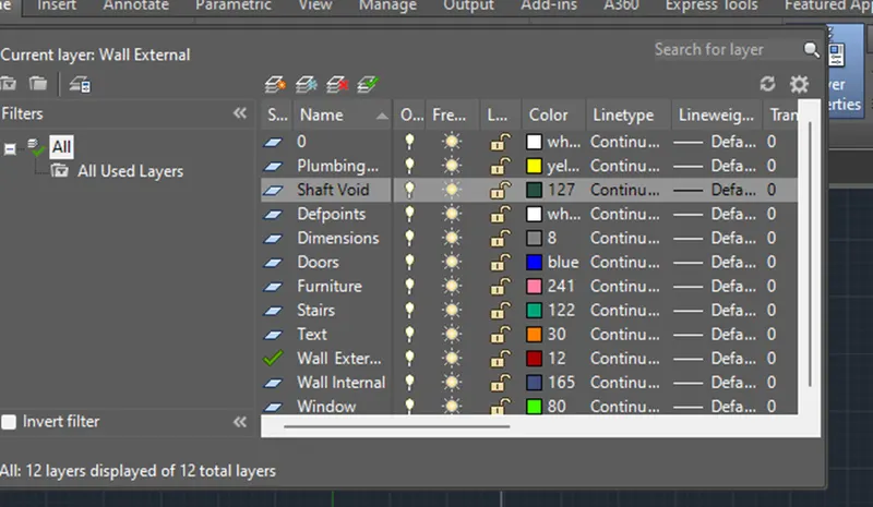
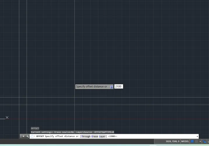
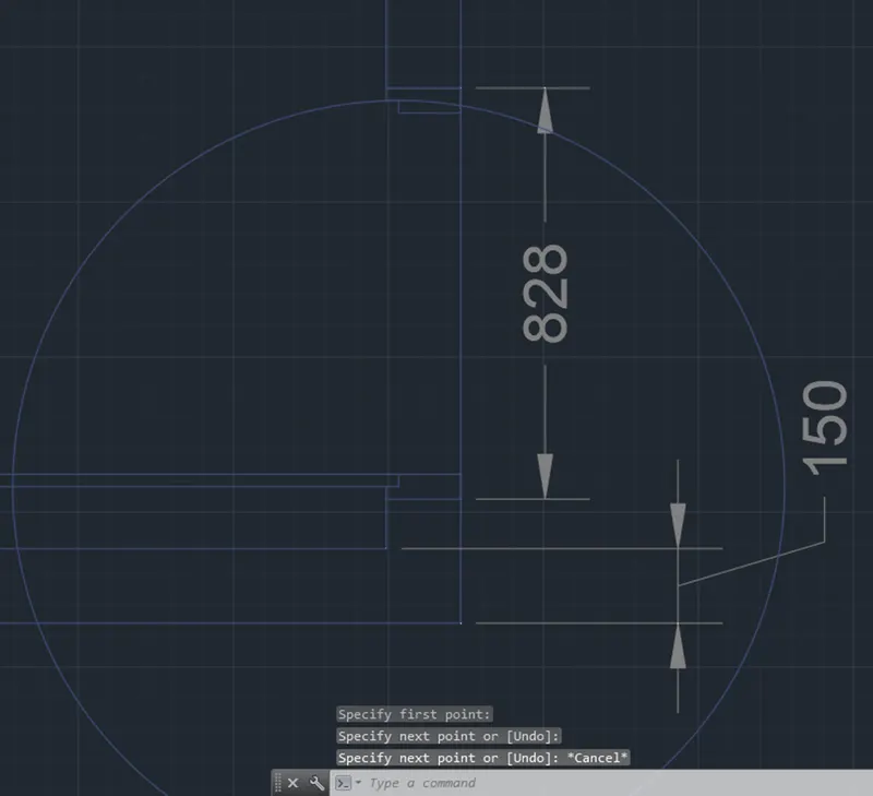
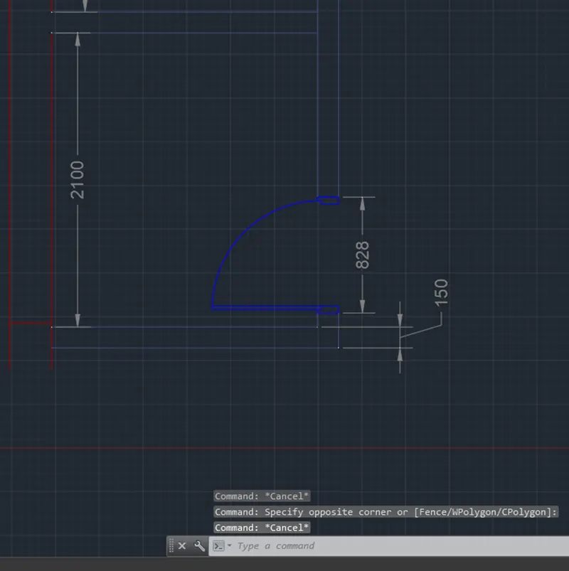
Completed Layout for Challenge 3