Drafting of various geometries using Chamfer, Fillet tool in AutoCad
The various commands used in this challenge are:
- Line
- Circle
- Rectangle
- Copy
- Offset
- Trim
- Polygon
- Point
- Rotate
- Fillet
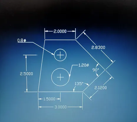
1.) AIM : To draw the given figure using AutoCAD:
A.) PROCEDURE:
Step 1: Drawing outer box
Type line in command box or select line from the draw tool bar
- Specify first point: Type (1,1) and press enter
- Specify next point: Type (4,1) and press enter
- Specify next point: Type @ 2.12<45 and press enter
- Specify next point: Type @ 2.83<135 and press enter
- Specify next point: Type @ -2,0 and press enter
Step 2: Drawing bottom Inner circle
Type circle in the command box or select circle from the draw toolbar
- Specify center point for circle: Type (2.5,2) and press enter
- Specify radius of circle or Diameter: Press diameter and type 1.2 and press enter
Step 3: Drawing top Inner circle
Type circle in the command box or select circle from the draw toolbar
- Specify center point for circle: Type (2.5,3.5) and press enter
- Specify radius of circle or Diameter: Press diameter and type 0.8 and press enter
RESULT:
The resultant figure is shown below with dimensions.
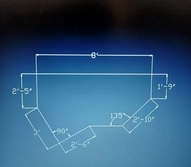
2.) AIM: To draw the given figure using AutoCAD
A.) PROCEDURE:
Step 1: Drawing right side of figure
Type line in command box or select line from the draw tool bar
- Specify first point: Type (1,9) and press enter
- Specify next point: Type @8’,0 and press enter
- Specify next point: Type @ 0, -1’9” and press enter
- Specify next point: Type @ 2’10” <225 and press enter
Step 2: Drawing left side of figure
Type line in command box or select line from the draw tool bar
- Specify first point: Turn on Osnap and select the top left end point or start point
- Specify next point: Type @ -2’5”,0 and press enter
- Specify next point: Type @ 3’ <300 and press enter
- Specify next point: Type @ 2’6” <30 and press enter
- Specify next point (Close: Exit: Undo): Turn on Osnap and select the last end point drawn in last step
RESULT:
The resultant figure is shown below with dimensions.
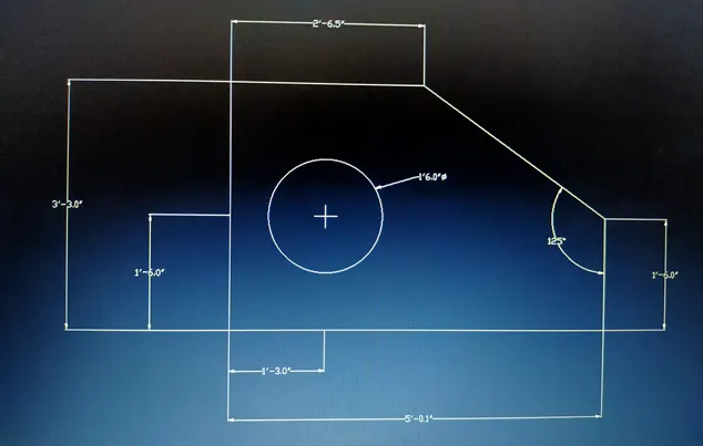
3.) AIM: To draw the given figure using AutoCAD
A.) PROCEDURE:
Step 1: Drawing outer box
Type line in command box or select line from the draw tool bar
- Specify first point: Type (9,5) and press enter
- Specify next point: Type @ 0, -1’6” and press enter
- Specify next point: Type @ -5’0.1”,0 and press enter
- Specify next point: Type @ 0, 3’3” and press enter
- Specify next point: Type @ 2’6.5”,0 and press enter
Step 2: Creating points for inner circle
Type PDMODE and press enter and type 3 and press enter
Type point in command box and press enter
Turn on polar tracking
- Keep the curser on bottom left corner of the box and then move is right side of that point for polar tracking and type 1’3” and press enter
- Keep the cursor on the last point created and move it up for polar tracking and type 1’6” and press enter
Step 3: Drawing Inner circle
Type Circle in the command box or select circle from the draw toolbar
- Specify center point for circle: Turn on Osnap and click on the point created for circle center
- Specify radius of circle or Diameter: Press diameter and type 1’6” and press enter
RESULT:
The resultant figure is shown below with dimensions.
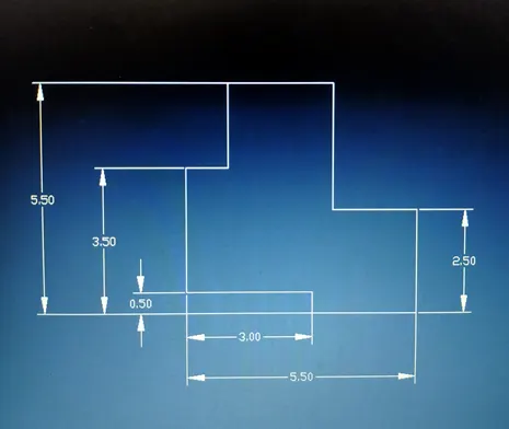
4.) AIM: To draw the given figure using AutoCAD
A.) PROCEDURE:
Step 1: Drawing outer box
Type line in command box or select line from the draw tool bar
- Specify first point: Type (1,1) and press enter
- Specify next point: Type @ 3,0 and press enter
- Specify next point: Type @ 0, -05 and press enter
- Specify next point: Type @ 2.5,0 and press enter
- Specify next point: Type @ 0,2.5 and press enter
- Specify next point: Type @ -2,0 and press enter
- Specify next point: Type @ 0,3 and press enter
- Specify next point: Type @ -2.5,0 and press enter
- Specify next point: Type @ 0, -2 and press enter
- Specify next point: Type @ -1,0 and press enter
RESULT:
The resultant figure is shown below with dimensions.
5. AIM: To draw the given figure using AutoCAD
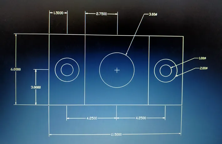
A.) PROCEDURE:
Step1: Drawing rectangle
Type rectangle in the command box or select rectangle from the draw toolbar
- Specify first corner point: Type (10,10) and press enter
- Specify other corner point or [ Area: Dimension: Rotation]: Click on dimensions
- Specify length for rectangle: Type 11.5 and press enter
- Specify width for rectangle: Type 6 and press enter and set the direction as first quadrant
Step 2: Drawing geometric center on the rectangle and the geometric center of left rectangle
Type line in command box or select line from the draw tool bar
- Specify first point: Type (13,10) and press enter
- Specify next point: Turn on perpendicular in Osnap and select the perpendicular point on opposite side of rectangle
Type PDMODE and press enter and type 3 and press enter
Turn on OSNAP and select center and geometric center
Type point in command box and press enter
- Specify a point: Select the geometric center of the rectangle
Type point in command box and press enter
- Specify a point: Select the geometric center of the left rectangle
Step 3: Drawing left side holes of figure and center hole
Type Circle in the command box or select circle from the draw toolbar
- Specify center point for circle: Turn on Osnap and click on the point as geometric center of rectangle
- Specify radius of circle or Diameter: Press diameter and type 3 and press enter
- Specify center point for circle: Turn on Osnap and click on the point as geometric center of left rectangle
- Specify radius of circle or Diameter: Press diameter and type 1 and press enter
- Specify center point for circle: Turn on Osnap and click on the point as geometric center of left rectangle
- Specify radius of circle or Diameter: Press diameter and type 2 and press enter
Step 4: Creating mirror image the holes and left rectangle
Type mirror in the command box and press enter or select mirror from the modify tool bar
- Select objects: Select the left rectangle, center point created and two circle holes and press enter
- Select first point of mirror line: Select the geometric center of the main rectangle
- Select second point of the mirror line: Turn on Orthomode and Select any edge along the length
- Erase source object [ Yes: No]: Click on No
RESULT:
The resultant figure is shown below with dimensions.
6. Aim: To draw the given figure using AutoCAD
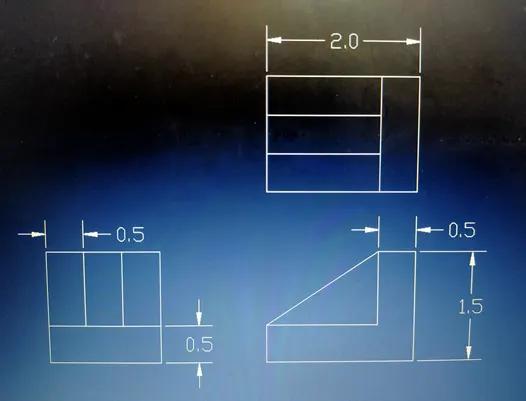
A.) PROCEDURE:
Step1: Drawing Left side view
Type rectangle in the command box or select rectangle from the draw toolbar
- Specify first corner point: Type (10,10) and press enter
- Specify other corner point or [ Area: Dimension: Rotation]: Click on dimensions
- Specify length for rectangle: Type 1.5 and press enter
- Specify width for rectangle: Type 0.5 and press enter and set the direction as first quadrant
- Specify first corner point: Turn on OSNAP and select the top left corner of the previously drawn rectangle
- Specify other corner point or [ Area: Dimension: Rotation]: Click on dimensions
- Specify length for rectangle: Type 0.5 and press enter
- Specify width for rectangle: Type 1 and press enter and set the direction as first quadrant
Type copy in command box or select copy command from the modify tool bar
- Select Objects: Select the rectangle drawn previously with dimensions 0.5X1 and press enter
- Specify base point: Select the bottom left corner of the rectangle selected
- Specify second point: Select the bottom right corner of the selected rectangle
- Specify second point: Select the bottom right corner of the first copied rectangle to draw another
Step2: Drawing Front view
Type rectangle in the command box or select rectangle from the draw toolbar
- Specify first corner point: Type (13,10) and press enter
- Specify other corner point or [ Area: Dimension: Rotation]: Click on dimensions
- Specify length for rectangle: Type 2 and press enter
- Specify width for rectangle: Type 0.5 and press enter and set the direction as first quadrant
Type or rectangle in the command box or select rectangle from the draw toolbar
- Specify first corner point: Turn on OSNAP and select the top right corner of the previously drawn rectangle Specify other corner point or [ Area: Dimension: Rotation]: Click on dimensions
- Specify length for rectangle: Type 0.5 and press enter
- Specify width for rectangle: Type 1 and press enter and set the direction as Second quadrant
Type line in command box or select line from the draw tool bar
- Specify first point: Turn on Osnap and select the top left corner of the bottom horizontal rectangle
- Specify next point: Turn on Osnap and select the top left corner of the top vertical rectangle
Type trim in command box or select trim from the modify tool bar
- Select objects: Press enter to select all the objects
- Press esc to cancel the command
Step3: Drawing Top view
Type rectangle in the command box or select rectangle from the draw toolbar
- Specify first corner point: Type (13,13) and press enter
- Specify other corner point or [ Area: Dimension: Rotation]: Click on dimensions
- Specify length for rectangle: Type 1.5 and press enter
- Specify width for rectangle: Type 0.5 and press enter and set the direction as first quadrant
Type or rectangle in the command box or select rectangle from the draw toolbar
- Specify first corner point: Turn on OSNAP and select the bottom right corner of the previously drawn rectangle
- Specify other corner point or [ Area: Dimension: Rotation]: Click on dimensions
- Specify length for rectangle: Type 0.5 and press enter
- Specify width for rectangle: Type 1.5 and press enter and set the direction as first quadrant
Type copy in command box or select copy command from the modify tool bar
- Select Objects: Select the rectangle drawn previously with dimensions 1.5X0.5 and press enter
- Specify base point: Select the bottom right corner of the rectangle selected
- Specify second point: Select the top right of the selected rectangle
- Specify second point: Select the top right corner of the first copied rectangle to draw another
RESULT:
The resultant figure is shown below with dimensions.
7. AIM: To draw the given figure using AutoCAD
A.) RESULT:
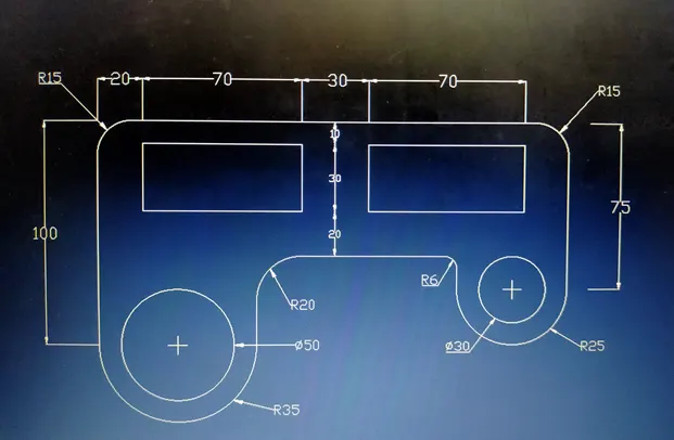
8. AIM: To draw the given figure using AutoCAD
A.) RESULT:
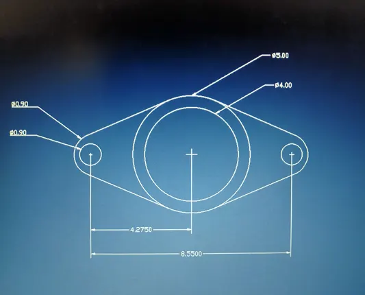
10. AIM: To draw the given figure using AutoCAD
A.) PROCEDURE:
Step 1: Drawing Squares
Type or polygon in command box or select polygon from the draw tool bar
- POLYGON Enter number of sides: Type 4 and press enter
- Specify center of the polygon: Type 10,10 and press enter
- Enter an option [Inscribed in Circle :: Circumscribed in Circle]: Click on Inscribed in Circle
- Specify radius of the circle: Turn on grid and select at the 5 units in horizontal and vertical direction
Type polygon in command box or select polygon from the draw tool bar
- POLYGON Enter number of sides: Type 4 and press enter
- Specify center of the polygon: Type 10,10 and press enter
- Enter an option [Inscribed in Circle :: Circumscribed in Circle]: Click on Inscribed in Circle
- Specify radius of the circle: Turn on grid and select at the 7 units in horizontal direction
Step 2: Drawing Square offsets
Type press enter or click offset from the modify tool bar
- Specify offset distance: Type 0.3 and press enter
- Select object to offset: Select the straight square and select inside of the square to offset
- Select object to offset: Select the inclined square and select outside of the square to offset
Step 3: Trimming
Type or trim in command box or select trim from the modify tool bar
- Select objects: Press enter to select all the objects
- Trim: Trim the portion as per the question
RESULT:
The resultant figure is shown below with dimensions.

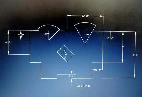
11. AIM: To draw the given figure using AutoCAD
A.) PROCEDURE:
Step 1: Drawing outer box
Type line in command box or select line from the draw tool bar
- Specify first point: Type (10,10) and press enter
- Specify next point: Type @0,-9’ and press enter
- Specify next point: Type @ 3’,0and press enter
- Specify next point: Type @ 0,-4’6” and press enter
- Specify next point: Type @ 4’6”,0 and press enter
- Specify next point: Type @ 0,1’2” and press enter
- Specify next point: Type @ 5’4”,0 and press enter
- Specify next point: Type @ 0,-1’2” and press enter
- Specify next point: Type @ 4’6”,0 and press enter
- Specify next point: Type @ 0,4’6” and press enter
- Specify next point: Type @ 3’,0and press enter
- Specify next point: Type @0,9’ and press enter
Step 2: Drawing Inner polygon
Type PDMODE and press enter and type 3 and press enter
Turn on polar tracking
Turn on OSNAP and select center and geometric center
Type point in command box and press enter
- Specify a point: Turn on OSNAP and keep the curser on the midpoint of top edge and start polar tracking to down and type 6’9” and press enter
Type polygon in command box or select polygon from the draw tool bar
- POLYGON Enter number of sides: Type 4 and press enter
- Specify center of the polygon: Select the point created before
- Enter an option [Inscribed in Circle :: Circumscribed in Circle]: Click on inscribed in Circle
- Specify radius of the circle: Type 3 and press enter
Step 3: Drawing V sections
Type PDMODE and press enter and type 3 and press enter
Turn on polar tracking
Turn on OSNAP and select center and geometric center
Type point in command box and press enter
- Specify a point: Turn on OSNAP and keep the curser on left top edge and start polar tracking to down and type 2’8” and press enter
Type point in command box and press enter
- Specify a point: Turn on OSNAP and keep the curser on right top edge and start polar tracking to down and type 3’7” and press enter
Type line in command box or select line from the draw tool bar
- Specify first point: Turn on OSNAP and Orthomode and select the point created on the left side
- Specify next point: Turn on Orthomode and draw a line to the right of certain distance
- Specify first point: Turn on OSNAP and Orthomode and select the point created on the right side
- Specify next point: Turn on Orthomode and draw a line to the left of certain distance
- Specify first point: Turn on OSNAP and Orthomode and select any point on the line created left side
- Specify next point: Turn on Orthomode and draw a line to the right of certain distance with an angle 450
- Specify first point: Turn on OSNAP and click on same point as before
- Specify next point: Turn on Orthomode and draw a line to the right of certain distance with an angle 1350
- Specify first point: Turn on OSNAP and Orthomode and select any point on the line created right side
- Specify next point: Turn on Orthomode and draw a line to the right of certain distance with an angle 600
- Specify first point: Turn on OSNAP and click on same point as before
- Specify next point: Turn on Orthomode and draw a line to the right of certain distance with an angle 1200
Type trim in command box or select trim from the modify tool bar
- Select objects: Press enter to select all the objects
- Trim: Trim the portions between v sections and inclined lines if longer than section
RESULT:
The resultant figure is shown below with dimensions.