Creating a Residence Layout, Seating plan, Toilet and Utility room plan using AutoCad
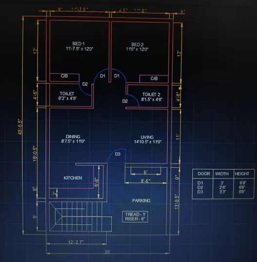
1.) AIM: To Sketch the layout of a residence as shown in the Figure 1.
PROCEDURE:
- The various commands used are: units, line, rectangle, fillet, copy, offset, dimension, layers, explode.
- The units must be set to engineering and select inches.
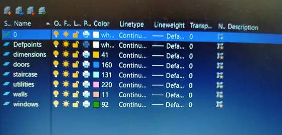
- Create various layers as shown below:
- With the help of the rectangle tool, create a rectangle of 25' and 43'6.5".
- Create a wall of 9" inwards with the help of offset.
- With the help of offset, draw horizontal and vertical lines as show in the given figure.
- Using the trim option, remove the unwanted parts from the drawing.
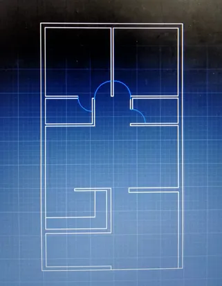
- Use different layers to make doors, windows and utilities.
RESULT:
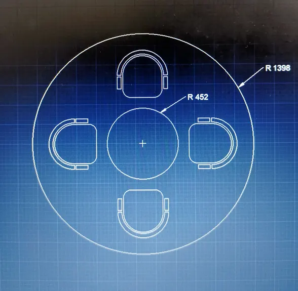
2.) AIM: To sketch the seating plan for an outdoor canopy.
PROCEDURE:
- Various commands used are: Line, rectangle, offset, trim, array, arc, fillet, circle, move.
- With the help of rectangle tool draw a rectangle of 500*280.
- Draw a semicircle above the rectangle.
- Offset the semicirclr with a distance of 20 and 70.
- Using fillet, cut the two bottom corners of the rectangle of radius 100.
- Draw 2 concentric circles of radius 452 and 1398 and make a vertical line passing through the center.
- Move the chair and allign it using the vertical line.
- With the help of array command, make 4 copies of chair seperated by 90 degrees each.
RESULT:
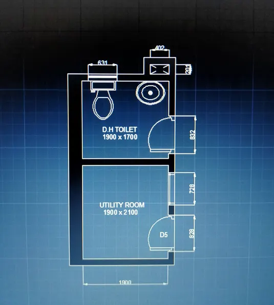
3.) AIM: To sketch the part plan for the toilers and utilities room.
PROCEDURE:
- The various commands used here are: offset, hatch, trim, dc, line, rectangle, fillet.
- The outer wall thickness are considerd as 300mm and inner wall thickness as 150mm.
- With the help of the dimensions given in the figure, rectangle is drawn.
- The doors, windows and ventilators are drawn and placed at their respective places.
- The toilet and sink are taken from dc command > sample> en-us> design center > house designer.dwg > blocks, and are placed at their respective places.
- Finally draw the duct with the following dimensions.
RESULT: