Drafting of various geometries using Chamfer, Fillet tool in AutoCad
AIM:
The aim is to draw all the diagram using Decimel, Engineering and Architectural units by given dimension.
1.
INTRODUCTION:
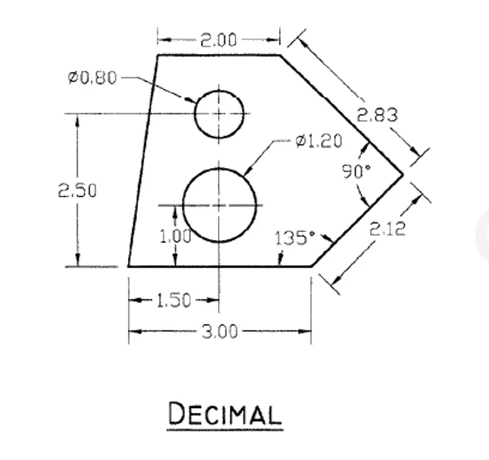
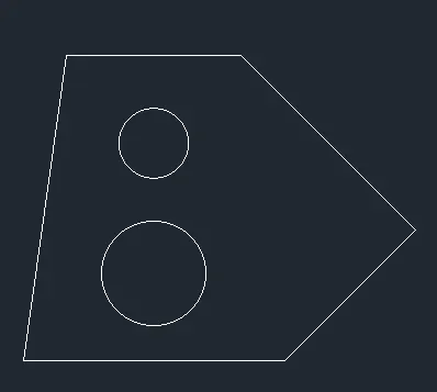
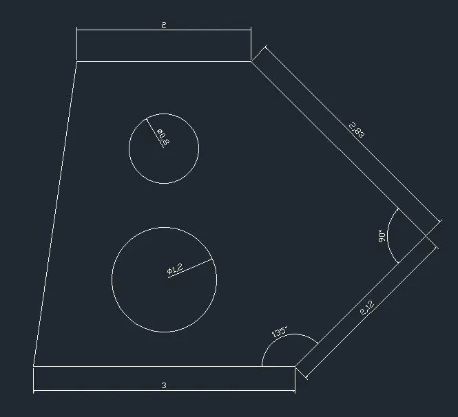
Draw the above diagram using Decimal unit by given dimension. In this decimal unit I have used the Meter unit. It is in the Drafting Setting (DS). The procedure is given below.
PROCEDURE:
- Open the AutoCAD and Create a New Sheet.
- Set the Unit as Decimal and Meters.
- Use the Line command and draw a line at a distance of 3.00 m in X-axis.
- Then use XL command and option Angle and Reference and select the reference line and give angle as 135.
- Then create a line over the XLine, then use the TR command and trim the unwanted lines.
- Then use LEN command and lengthen use option Total and put the length as 2.12 and lengthen the last line we have drawn.
- Again use the XL command and option Angle and Reference and select the last line as reference line and give the angle as 90.
- Then create a line over the XLine, then use the TR command and trim the unwanted lines.
- Then use LEN command and lengthen use option Total and put the length as 2.83 and lengthen the last line we have drawn.
- Then use the Line command and draw a line at a distance of 2.00 in -X-axis.
- Then Join the end point of the last line and starting point.
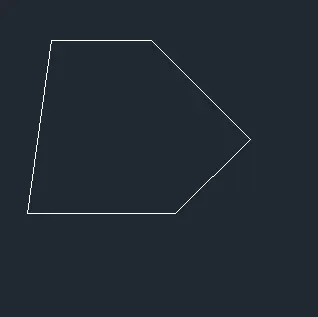
- Then use the OSnap setting and select the Center point, End point and Mid point.
- Use the line Command and using the midpoint of the 3.00 m line draw a line at a distance of 1.00 m in Y-axis.
- Then use Circle command and use the end point of the last line as center of the circle and give the Diameter as 1.2 m.
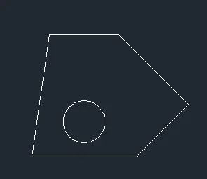
- Use the line command and in the center of circle draw a line at a distance of 1.5 m.
- Use the Circle command and using the end point of the last line as a center point of circle draw a circle at a Diameter of 0.8 m.
- Delete the unwanted lines.
- Save the Drawing (Ctrl+S).
RESULT:
2.
INTRODUCTION:
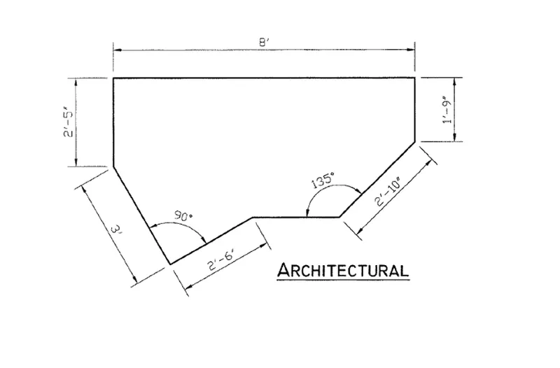
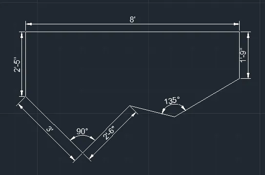
Draw the above diagram using Architectural unit by given dimension. In this Architectural unit I have used the Inches unit. It is in the Drafting Setting (DS). The procedure is given below.
PROCEDURE:
- Open the AutoCAD and Create a New Sheet.
- Set the Unit as Architectural and Inches.
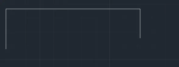
- Use the Line command and draw a line at a distance of 2'1" in Y-axis.
- Then draw a line at a distance of 8' in X-axis.
- Then draw a line at a distance of 1'9" in -Y-axis.
- Draw a line at a distance of 3' in Y-axis seperately. And 2'6" line in X-axis. Then use RO command and rotate it for 45 degree angle.
- Then fit it in the correct point in the drawing.
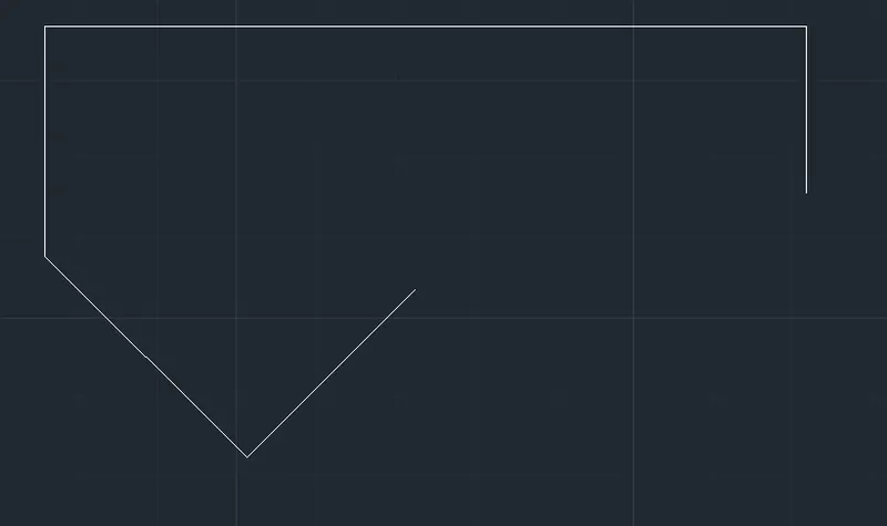
- Use the XL command draw the other line in the angle of 135 degree.
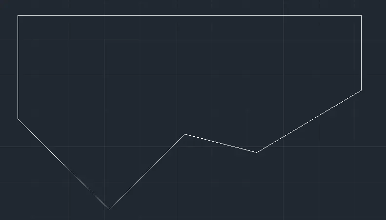
- Save the Diagram (Ctrl+S).
RESULT:
3.
INTRODUCTION:
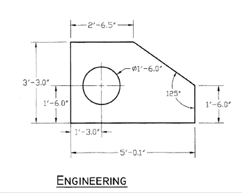
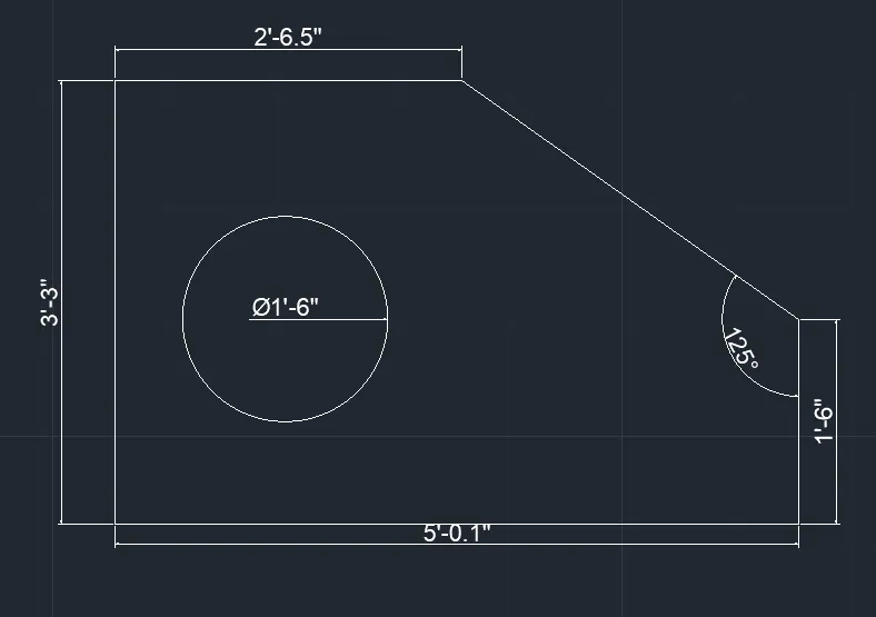
Draw the above diagram using Engineering unit by given dimension. In this Engineering unit I have used the Inches unit. It is in the Drafting Setting (DS). The procedure is given below.
PROCEDURE:
- Open the AutoCAD and Create a New Sheet.
- Set the Unit as Engineering and Inches.
- Use the Line command and draw a line at a distance of 5'0.1" in X-axis.
- Then draw a line at a distance of 1'6.0" in Y-axis.

- Then use XL command and option Angle and Reference line and select the reference line and give the angle as 125 degree.
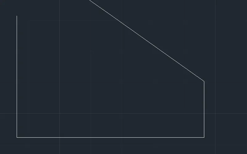
- Then from the starting point draw a line at a distancce of 2'6.5".
- Then use the TR command and trim the excess line.
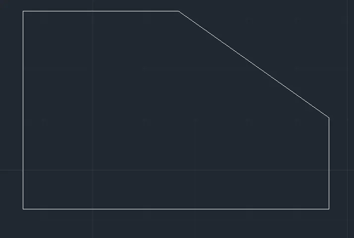
- From the end point of the first line draw a line at a distance of 1'3" in X-axis and 1'6" in Y-axis.
- Then use the Circle command and set the end point of last point as the center point and draw a circle at a Diameter of 1'6".
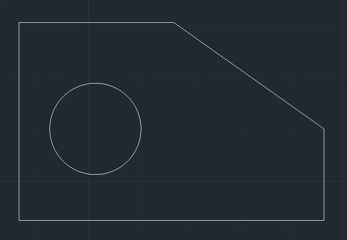
- Save the Drawing (Ctrl+S).
RESULT:
4.
INTRODUCTION:
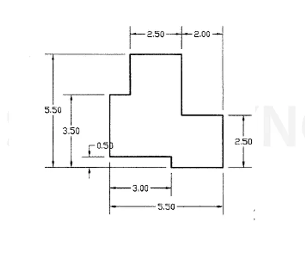
Draw the above diagram using Decimal unit by given dimension. In this decimal unit I have used the Meter unit. It is in the Drafting Setting (DS). The procedure is given below.
PROCEDURE:
- Open the AutoCAD and Create a New Sheet.
- Set the Unit as Decimal and Meters.
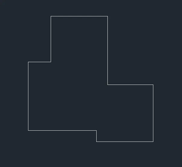
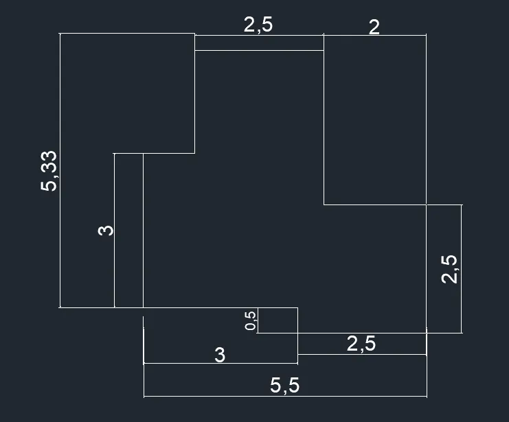
- Use the Line command and draw a line at a distance of 3.00 m in X-axis and 0.50 in -Y-axis.
- And 2.50 in X-axis then 2.50 in Y-axis and 2.00 in -X-axis and 3.00 in Y-axis and 2.50 in -X-axis and 2.00 in -Y-axis.
- Then click the starting point and draw a line at a distance of 3.00 in Y-axis and joint the two end points.
- Save the Drawing (Ctrl+S).
RESULT:
5.
INTRODUCTION:
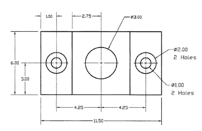
Draw the above diagram using Decimal unit by given dimension. In this decimal unit I have used the Meter unit. It is in the Drafting Setting (DS). The procedure is given below.
PROCEDURE:
- Open the AutoCAD and Create a New Sheet.
- Set the Unit as Decimal and Meters.
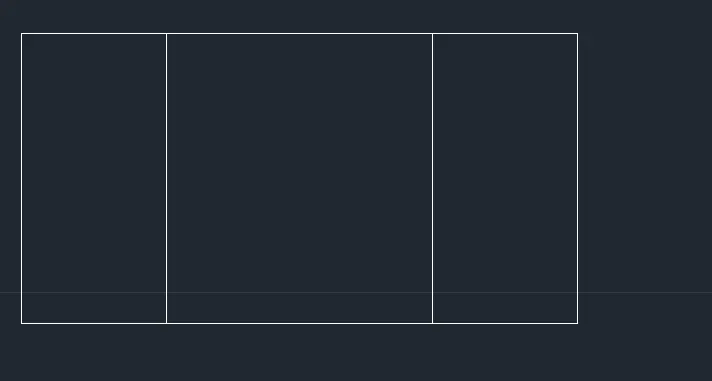
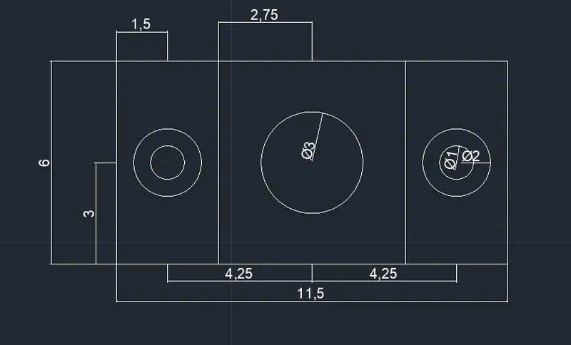
- Use the Line command and draw a line at a distance of 11.50 in X-axis and 6.00 in Y-axis and 11.50 in -X-axis and 6.00 in -Y-axis.

- Use the OFFSET command and offset the 6.00 m line at a distance of 3.00 and 5.50 and again 8.50m.
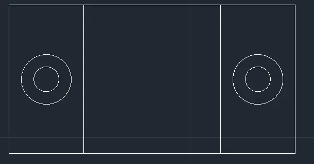
- Use the Circle command and draw a circle at a center point of the first rectangle in the Diameter of 1.00 and 2.00m.
- Use the CO command and copy it and place the base point in the center of the last rectangle.
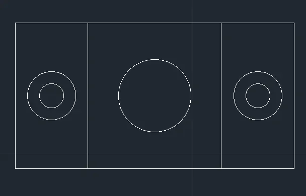
- Then again use the Circle command and draw a circle at the center point of the second rectangle at a Diameter of 3.00m.
- Save the Drawing (Ctrl+S).
RESULT:
6.
INTRODUCTION:
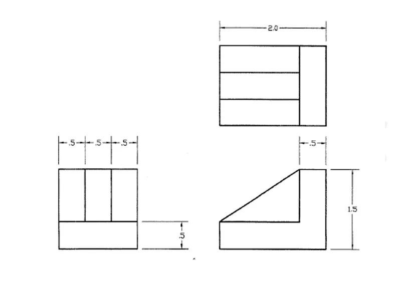
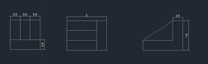
Draw the above diagram using Decimal unit by given dimension. In this decimal unit I have used the Meter unit. It is in the Drafting Setting (DS). The procedure is given below.
PROCEDURE:
- Open the AutoCAD and Create a New Sheet.
- Set the Unit as Decimal and Meters.
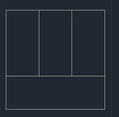
- Use the Line command and draw a line at a distance of 1.5 in X-axis and 0.5 in Y-axis and 1.0 in Y-axis and 1.5 in -X-axis and 1.5 in -Y-axis.
- Then use the OFFSET command and select the 1.0 m length and offset it at a distance of 0.5m and 1m.
- Click the start point.
- Use the Line command and draw a line at a distance of 2.0m in X-axis and 1.5m in Y-axis and 0.5m in -X-axis and 1.5 in -X-axis and 1.5 in -Y-axis.
- Use the OFFSET command and select the 1.5 m length line and offset it at a distance of 0.5m.
- Then again use the OFFSET command and select the 1m length line and offset it at a distance of 0.5 and 1m.

- Click the Start point.
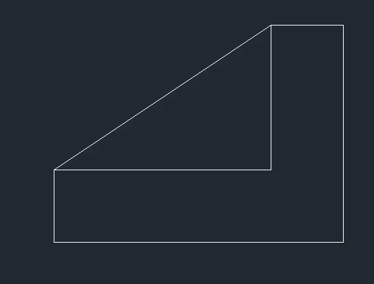
- Use the line command and draw a line at a distance of 2.0 m in X-axis and 1.5 in Y-axis and 0.5 in -X-axis and 1.0 in -Y-axis and 1.5 in -X-axis.
- Join the End points.
- Save the Drawing (Ctrl+S).
RESULT:
7.
INTRODUCTION:
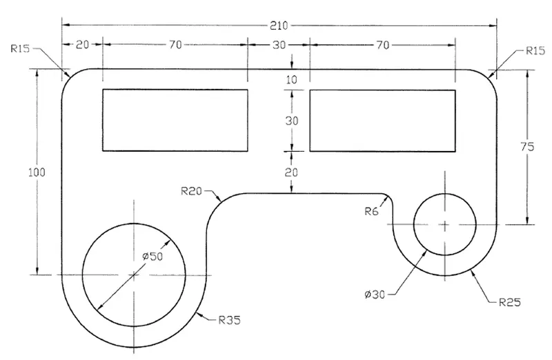
Draw the above diagram using Decimal unit by given dimension. In this decimal unit I have used the Meter unit. It is in the Drafting Setting (DS). The procedure is given below.
PROCEDURE:
- Open the AutoCAD and Create a New Sheet.
- Set the Unit as Decimal and Meters.
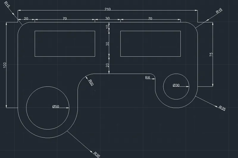
- Use the Line command and draw a line at a distance of 210 in X-axis and 75 in -Y-axis.
- Then from the starting point draw a line at a distance of 100 in -Y axis.
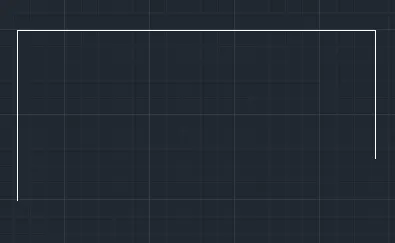
- Use the Osnap command and select the center point and then use line command and draw a line for 70 in X axis and use the circle command and draw a circle at a Diameter of 50.
- Then use arc command and Start,End,Radius and draw an arc at a Radius of 35.
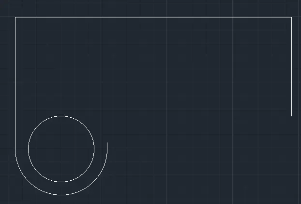
- Use line command and draw a line for 50 in -X axis and use the circle command and draw a circle at a Diameter of 30.
- Then use arc command and Start,End,Radius and draw an arc at a Radius of 25.
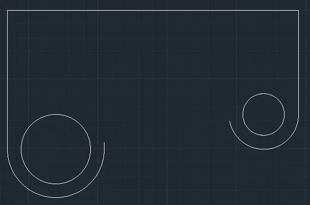
- Then draw a line in the mid point of 210 length line and join them in the arc.
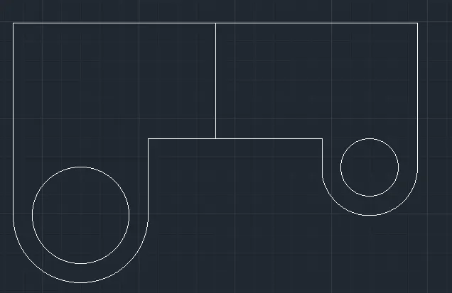
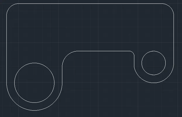
- Use the Fillet command and fillet the corners of the line at a Radius of 15,20 and 6.
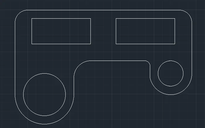
- Use REC command and draw a rectangle at a dimension of 70x30 in both sides of mid point.
- Save the Drawing (Ctrl+S).
RESULT:
8.
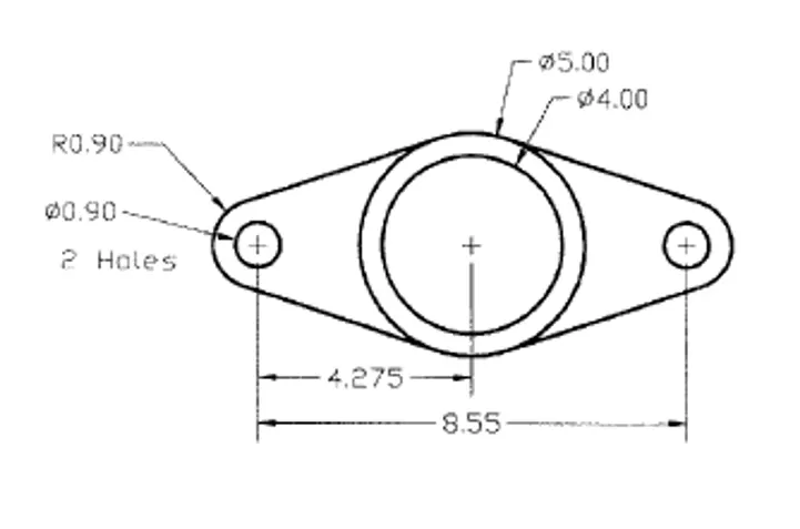
INTRODUCTION:
Draw the above diagram using Decimal unit by given dimension. In this decimal unit I have used the Meter unit. It is in the Drafting Setting (DS). The procedure is given below.
PROCEDURE:
- Open the AutoCAD and Create a New Sheet.
- Set the Unit as Decimal and Meters.
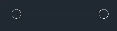
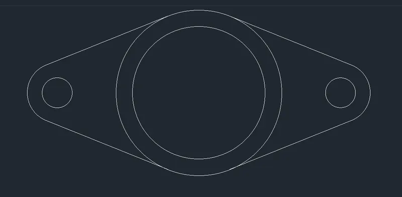
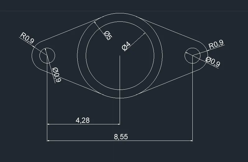
- Use Line command and draw a line at a distance of 8.55 m in X-axis.
- Then Use the Circle command and draw a circle at both end points as center point at Diameter of 0.90.
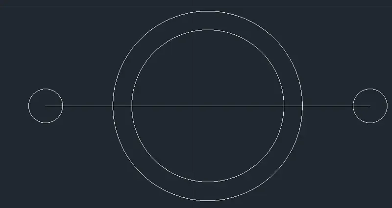
- Then use a Circle command and draw a circle. Take the midpoint of the line as center point of a circle and give the Diameter as 4.0 and 5.0.
- Then use the Circle command again and draw a circle at a radius of 0.9 in each side.
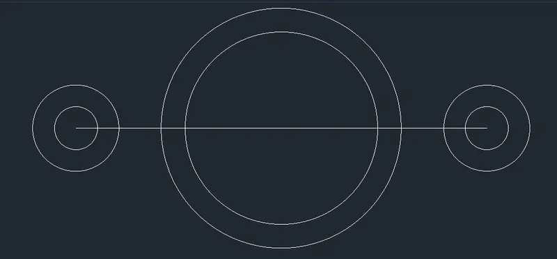
- Now delete the line.
- Next use the OS command and click the Tangent.
- Now ON the OSNAP and drag in circles and click the tangent point and join them.
- Then TRIM or delete the unwanted lines.
- Save the Drawing (Ctrl+S).
RESULT:
9.
INTRODUCTION:
Draw the above diagram using Engineering unit by given dimension. In this Engineering unit I have used the Inches unit. It is in the Drafting Setting (DS). The procedure is given below.
PROCEDURE:
- Open the AutoCAD and Create a New Sheet.
- Set the Unit as Engineering and Inches.
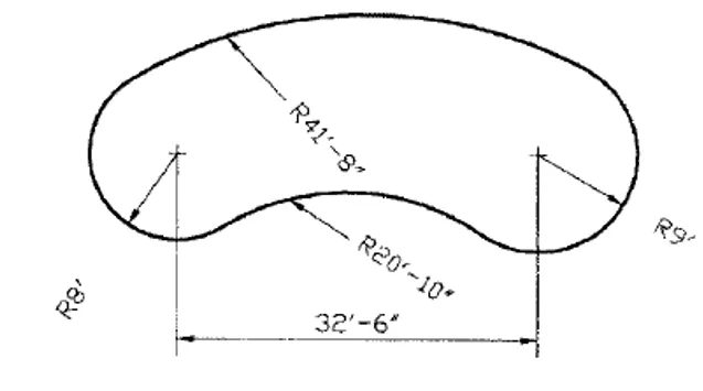
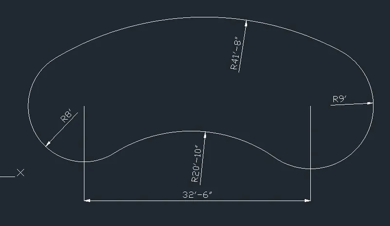
- Use the Line command and draw a line at a distance of 32'6".
- Then use the Circle command and set the start point of the line as the center point of the circle and draw a circle at a Radius of 8'.
- Then use the Circle command and set the end point of the line as the center point of the circle and draw a circle at a Radius of 9'.
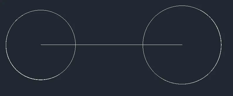
- Go to OS settings and select Tangent.
- Then again use the Circle command and click the option Tan Tan Radius and select the tangent point of two circles and give the radius as 41'8".
- Do it again with the radius of 20'10" for below.
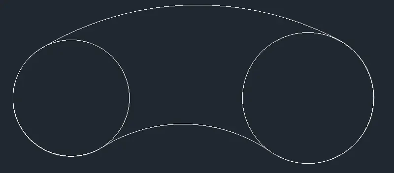
- Use the TR command and trim the unwanted parts.
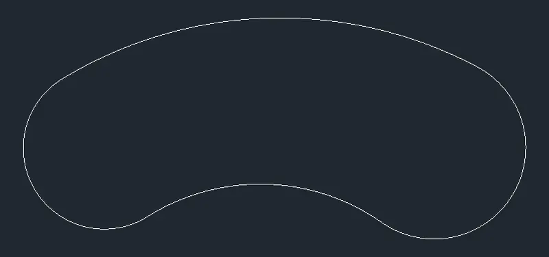
- Save the Drawing (Ctrl+S).
RESULT:
10.
INTRODUCTION:
Draw the above diagram using Decimal unit by given dimension. In this decimal unit I have used the Meter unit. It is in the Drafting Setting (DS). The procedure is given below.
PROCEDURE:
- Open the AutoCAD and Create a New Sheet.
- Set the Unit as Decimal and Meters.
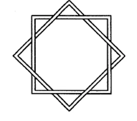
- Use the REC command draw a rectangle at a dimension of 10X10m.
- Then use OFFSET command and offset it for 0.5 m.
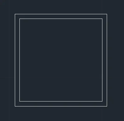
- Draw it again seperately.
- Then use RO command and rotate it for 45 degree. And Fit the base point in the drawing.
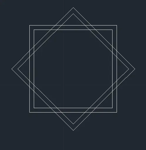
- Now use the TR command and trim the lines as per the given drawing.
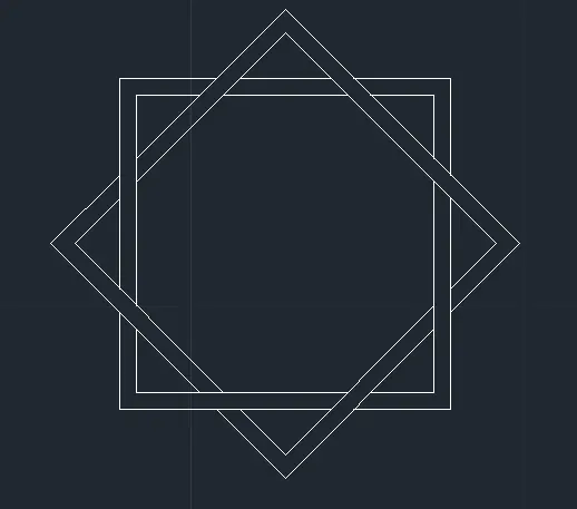
- Save the Drawing (Ctrl+S).
RESULT:
11.
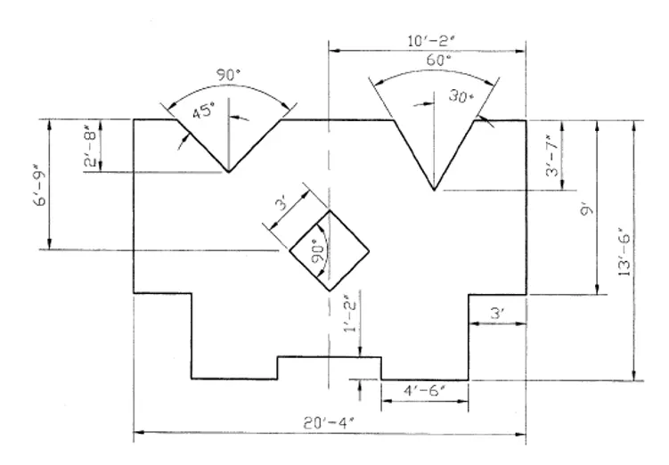
INTRODUCTION:
Draw the above diagram using Engineering unit by given dimension. In this Engineering unit I have used the Inches unit. It is in the Drafting Setting (DS). The procedure is given below.
PROCEDURE:
- Open the AutoCAD and Create a New Sheet.
- Set the Unit as Engineering and Inches.
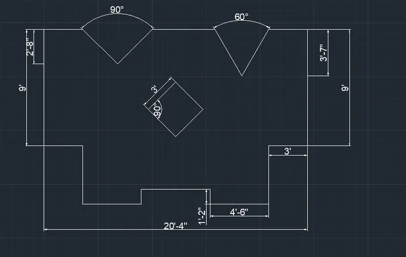
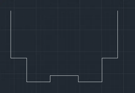
- Use Line command and draw a line at a distance of 9' in -Y-axis and 3' in X-axis and 4'6" in -Y-axis and 4'6" in X-axis and 1'2" in Y-axis and 5'4" in X-axis and 1'2" in -Y-axis and 4'6" in X-axis and 4'6" in Y-axis and 3' in X-axis and 9' in Y-axis.
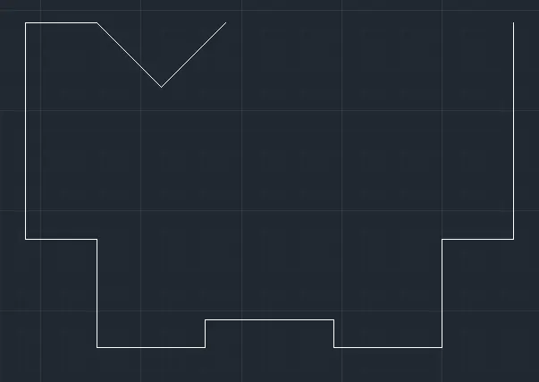
- Then draw a mid line in the drawing and use XL command and draw a line at an angle of 90 degree and in the length of 2'8".
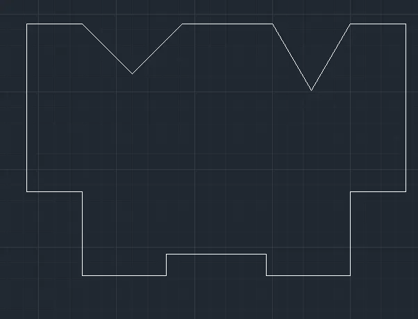
- Then draw a line at an angle of 60 degree in the other end in the length of 3'7" and join the lines.
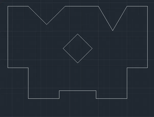
- Now draw a midline again and create a rectangle at an angle of 90 degree and dimension of 3x3.
- Save the Drawing (Ctrl+S).
RESULT: