Creating a Floor plan, Footing detail and Isometric view using AutoCad
AIM:
The aim is to draw C.S. OF LOAD BEARING WALL OVER SPREAD FOOTING, C.S ISOLATED FOOTING, LINE DIAGRAM OF A TWO BEDROOM BUILDING, C.S. OF LOAD BEARING WALL SHOWING FOUNDATION DETAILS, ISOMETRIC VIEW OF STEPS and ISOMETRIC VIEW OF GABLE WALL using AUTOCAD with the given dimensions.
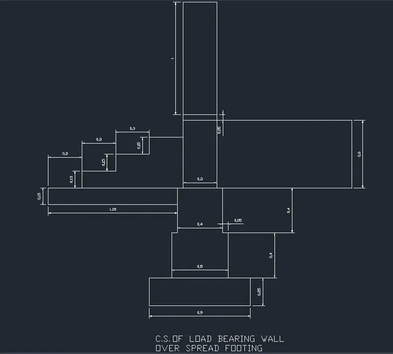
1. C.S. OF LOAD BEARING WALL OVER SPREAD FOOTING
INTRODUCTION:
Draw the C.S. of Load Bearing Wall over Spread Footing by the given dimension shown in below.
PROCEDURE:
- Start the AutoCAD application.
- Create a New Work sheet.
- Set the unit as Decimel and Millimeters.
- Put the Line (L) command in the command box.
- Put the Ortho ON.
- Click a start point.
- By using Direct Distance Method, draw a line at a distance of 0.9 in X-axis.
- Then draw a line at a distance of 0.25 in Y-axis.
- Then again draw a line at a distance of 0.9 in -X-axis.
- Then close the line to the start point.
- From the previous line create a line at 0.2 distance in X-axis and from that point create a line at a distance of 0.4 in Y-axis.
- Create a line at a distance of 0.05 in X-axis. And create a line at a distance of 0.4 in Y-axis.
- Again create a line at a distance of 0.05 in X-axis and a line at a distance of 0.6 in Y-axis and 0.05 in Y-axis and again 1 in Y-axis.
- And create a line at a distance of 0.3 in X-axis and a line at a distance of 1 in -Y-axis and 0.05 in -Y-axis again 0.6 at -Y-axis.
- Then create a line at a distance of 0.05 in X-axis and 0.4 in -Y-axis again 0.05 in X-axis and 0.4 in -Y axis.
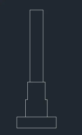
- Now join the end point of the length of 1 in Y and -Y axis. As well as the 0.05 in Y and -Y axis and 0.6 in Y and -Y axis end points.
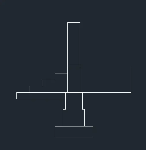
- Then Create a line at a right side of the drawing from the starting point of the 0.6 in -Y-axis and draw a line at a distance of 1.15 in X-axis and 0.6 in Y-axis and again a line at a distance of -X-axis.
- In the left side of the drawing at the starting point of the 0.6 in Y-axis draw a line at a distance of 1.15 in -X-axis and 0.15 in -Y-axis and again 1.15 in X-axis.
- In the previous line in distance 1.15 in -X axis click the end point and create a line at a distance of 0.3 in X axis and 0.15 in Y-axis and again 0.3 in X-axis and 0.15 in Y-axis and again 0.3 in X-axis and 0.15 in Y-axis and at last again 0.3 in X axis to finish the drawing.
- Save the drawing using (Ctrl+S).
RESULT:
2. C.S. ISOLATED FOOTING
INTRODUCTION:
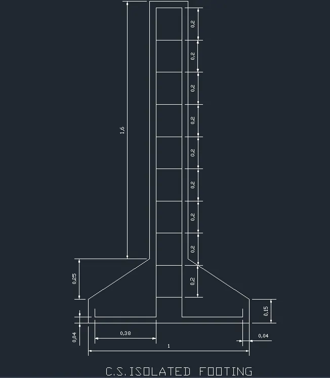
Draw the C.S. Isolated Footing by the given dimension shown in below.
PROCEDURE:
- Start the AutoCAD application.
- Create a New sheet.
- Set the unit as Decimel and Millimeters.
- Put the Line (L) command in the command box.
- Put the Ortho ON.
- Click a start point.
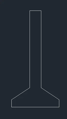
- Create a line at a distance of 1.00 in X-axis.
- Then draw a line at a distance of 0.15 in Y-axis and draw an inclined line at a distance of @-0.38, 0.25.
- Then draw a line at a distance of 1.6 in Y-axis.
- Then a line at a distance of 0.16 in -X-axis.
- Then a line at a distance of 1.6 in -Y-axis.
- Then an inclined line at a distance of @-0.38,-0.25.
- Then a line at a distance of 0.15 in -Y-axis.
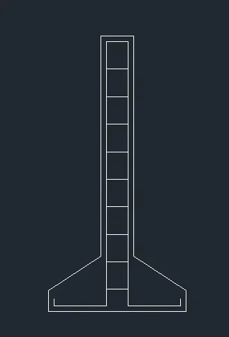
- Create a line from the starting point at a distance of 0.04 X-axis and 0.04 in Y-axis and create a line at 0.38 in X-axis and a line at 0.14 in Y-axis and 0.16 in X-axis again 0.14 in -Y-axis.
- Use the COPY command and copy the 3 previous lines and enter a distance as 0.2 and create it 9 times like in the below diagram.
- Save the drawing using (Ctrl+S).
RESULT:
3. LINE DIAGRAM OF A TWO BEDROOM BUILDING
INTRODUCTION:
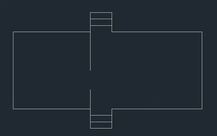
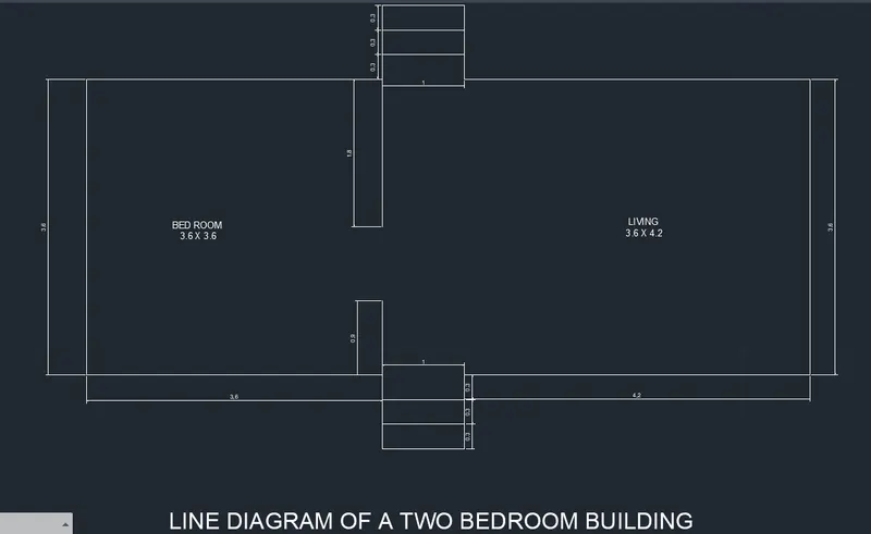
Draw the Line Diagram of a Two Bedroom Building by the given dimension shown in below.
PROCEDURE:
- Start the AutoCAD application.
- Create a new sheet.
- Set the unit as Decimel and Millimeters.
- Put the Line (L) command in the command box.
- Put the Ortho ON.
- Click a start point.
- Create a line at a distance of 3.6 in X-axis.
- Then from the end point of this line draw a line at a distance of 0.9 in Y-axis.Then click ESC.
- Again from the end point of the first line draw a line at a distance of 0.3 in -Y-axis and 1in X-axis and 0.3 in Y-axis.
- Then copy the previous 3 lines and copy it at a distance of 0.3 in -Y-axis.

- From the first end point of the 0.3 line create a line at a distance of 4.2 in X-axis.
- Then draw a line at a distance of 3.6 in Y-axis and again draw a line at a distance of 4.2 in -X-axis.
- Then draw a line at a distance of 0.3 in Y-axis and 1 in -X-axis and 0.3 in -Y-axis.
- Then Copy it and draw at a distance of 0.3 in Y-axis.
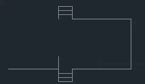
- Then from the end point of the first 0.3 line draw a line at a distance of 3.6 in -X-axis and 3.6 in -Y-axis.
- Save the drawing using (Ctrl+S).
RESULT:
4. C.S. OF LOAD BEARING WALL SHOWING FOUNDATION DETAILS
INTRODUCTION:
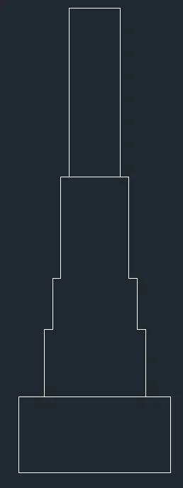
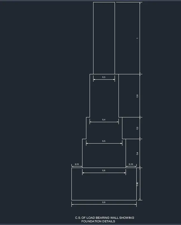
Draw the C.S. of Load Bearing Wall Showing Foundation Details by the given dimension shown in below.
PROCEDURE:
- Start the AutoCAD application.
- Create a new sheet.
- Set the unit as Decimel and Millimeters.
- Put the RECTANGLE (REC) command in the command box.
- Put the Ortho ON.
- Click a start point.
- Create a Rectangle at a distance of 0.9x0.45.
- Then Using LINE (L) Command in the end point of the length draw a line at a distance of 0.15 in X-axis and 0.4 in Y-axis and 0.05 in X-axis and 0.3 in Y-axis and 0.05 in X-axis and 0.6 in Y-axis and 0.05 in X-axis and 1 in Y-axis and 0.3 in X axis.
- Then line at a distance of 1 in -Y-axis and 0.05 in X-axis and 0.6 in -Y-axis and 0.05 in X-axis and 0.3 in -Y-axis and 0.05 in X-axis and 0.4 in -Y-axis.
- Then join the start point of the line of distance 1 in Y and -Y axis.
- Save the drawing using (Ctrl+S).
RESULT:
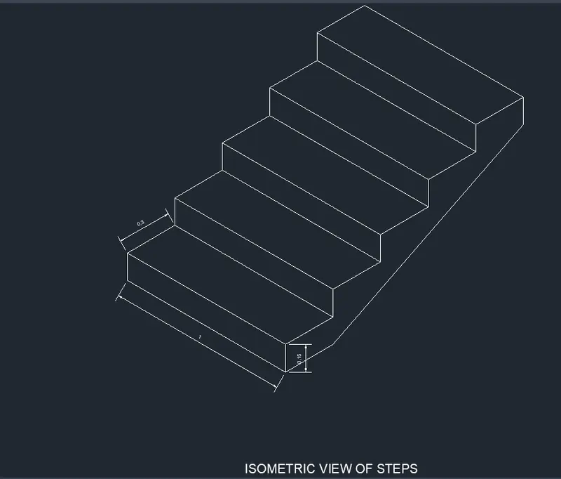
5. ISOMETRIC VIEW OF STEPS.
INTRODUCTION:
Draw the Isometric View of Steps by the given dimension shown in below.
PROCEDURE:
- Start the AutoCAD application.
- Create a new sheet.
- Set the unit as Decimel and Millimeters.
- Write Draft Settings (DS) in the command box.
- In the Dialog box select the Isometric view.
- Click the start point.
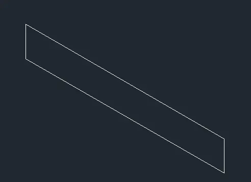
- Then click the isoplane left view then create a line at a distance of 1 X-axis and 0.15 in Z-axis and 1 in -X-axis and 0.15 in -Z-axis.
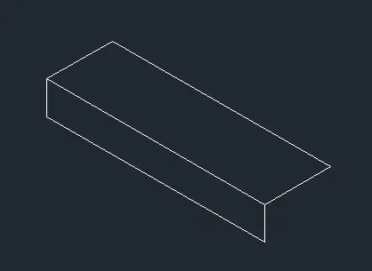
- Then use the Isoplane top view and draw a line at a distance of 0.3 in Z-axis and 1 in -X-axis and 0.3 in -Z-axis.
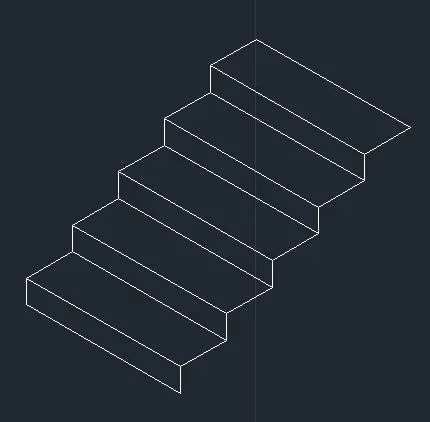
- Repeate the same process for 4 times.
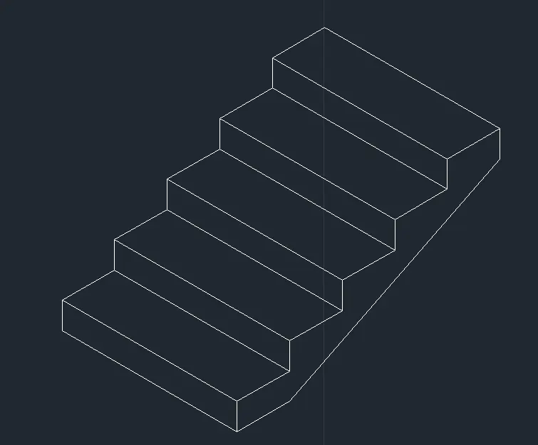
- Then join the side view using isoplane right view.
- Save the drawing using (Ctrl+S).
RESULT:
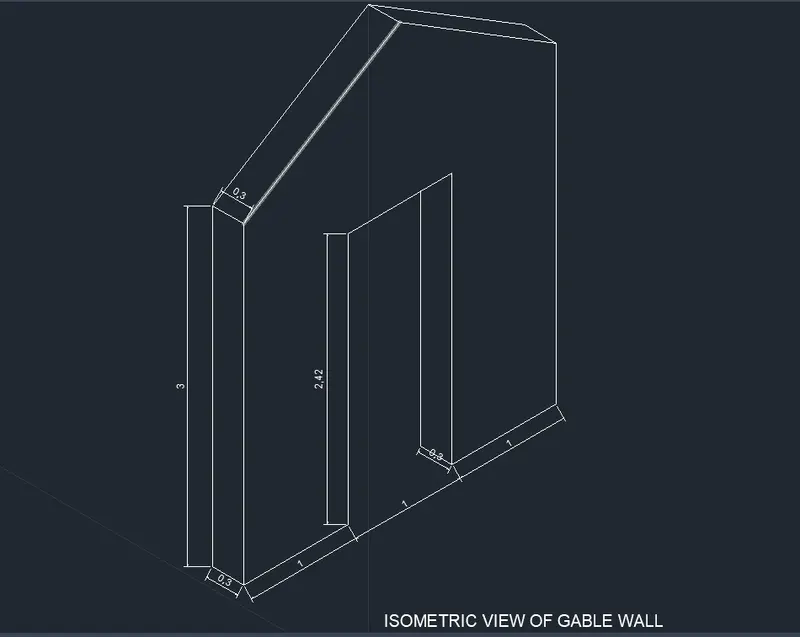
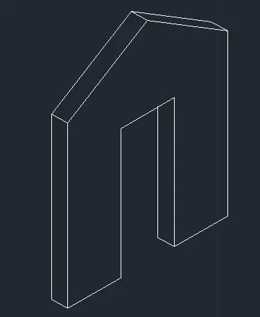
6. ISOMETRIC VIEW OF GABLE WALL.
INTRODUCTION:
Draw the Isometric View of Gable Wall by the given dimension shown in below.
PROCEDURE:
- Start the AutoCAD application.
- Create a new sheet.
- Set the unit as Decimel and Millimeters.
- Write Draft Settings (DS) in the command box.
- In the Dialog box select the Isometric view.
- Click a starting point.
- Draw a line at a distance of 1 in X-axis and 2.42 in Z-axis and 1 in X-axis and 2.42 in -Z-axis and 1 in X-axis and 3 in Z axis.
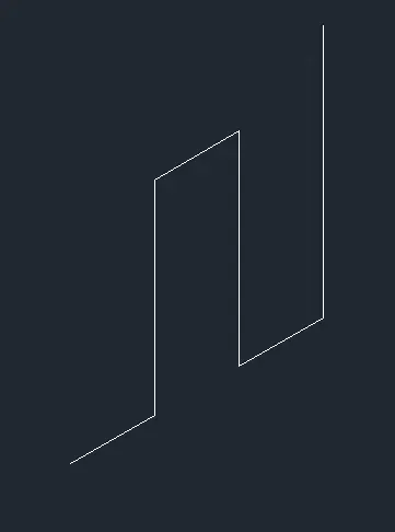
- From the starting point draw a line at a distance of 0.3 in -X-axis and 3 in Z-axis and 0.3 in X-axis and 3 in -Z-axis.
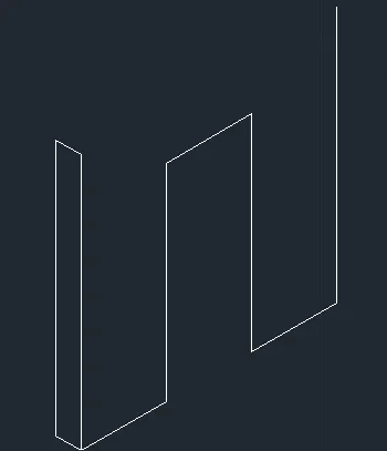
- From the end point of 2.42 length line draw a line at a distance of 0.3 in -Z-axis and 2.12 in X-axis.
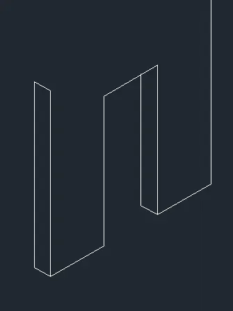
- From the mid point create a line at a distance of 1.5 in Z-axis. And then Join the end points like a truss.
- Save the drawing using (Ctrl+S).
RESULT: