Drafting of various geometries using Chamfer, Fillet tool in AutoCad
AIM: To draw the geometries using Chamfer, fillet tool in Autocad.
Commands used in this challenge are
- Line 'L'
- Copy 'CO' or 'CP'
- PolyLine 'PL'
- Trim 'TR'
- Offset 'O'
- Isometric View
- Text
- Dimension 'DIM'
- Dimstyle 'D'
- MATCHPROP 'MA'
- Move 'M'
- Mirror 'MI'
- Fillet 'F'
- Erase 'E'
- Rotate
- PTYPE
- POINT
- CIRCLE
- RECTANGLE
- CHAMFER
- FILLET
Q.1) Decimal
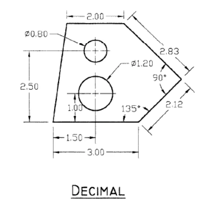
Aim:- To draw the above figure using AutoCAD
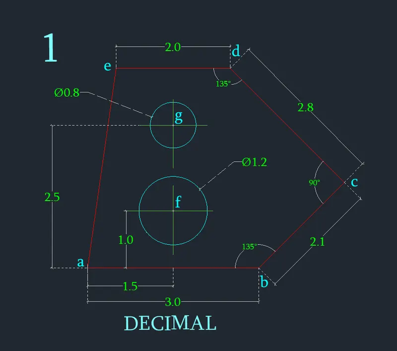
Procedure:-
- line command
- starting point 'a' ( 0, 0 )
- from 'a' 3.0 unit left till 'b'
- after that move 2.1 at an angle of 45 degrees to 'c'. (2.1<45)
- then 2.8 at an angle of 90 degrees inside to 'd'
- 2.0m on left side at 'e'
- close
- else
- type PTYPE command and select point
- mark point 'f' & 'g' at distance 1.5 from point 'a' and at height 1.0 & 2.50 from base
- circle command
- select draw circle from diameter
- now at point 'f' draw circle of dia 1.20 & at point 'g' draw circle of dia 0.8
- else
Result:-
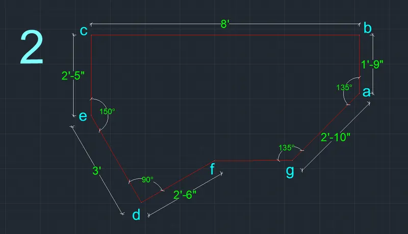
Q.2) ARCHITECTURAL
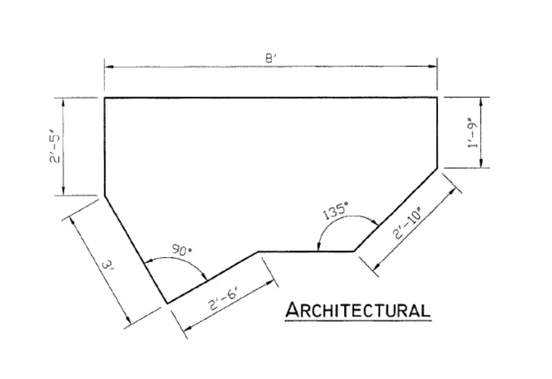
Procedure:-
- line command
- starting point 'g'
- a = 2'-10"< 45 degree
- b = 1'-9" in upward
- c = 8' in leftward
- e = 2'-5" in downward
- d = 3' @ 150degree from 'e'
- f = 2'-6"<90 degree inside
- close
- using DIM command show the dimension of each line & angles also
Result:-
 Q.3) ENGINEERING
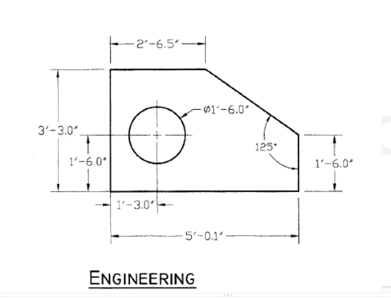 Aim:- To draw the above figure using AutoCADProcedure:-
- new file
- polyline command
- the starting point is 'a'
- 'b' at distance 2'-6.5" in the left direction
- 'c' at distance 3'-3" in a downward direction
- 'd' at distance 5'-0.1" in the left direction
- 'e' at distance 1'-6" in an upward direction
- close
- select a suitable point type by using the PTYPE command
- mark a point 'f' using point command at a distance 1'-3" left from 'c' & 1'-6" up from 'c'.
- esc
Result:-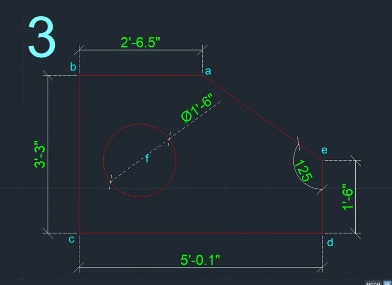 Q.4)
Q.4)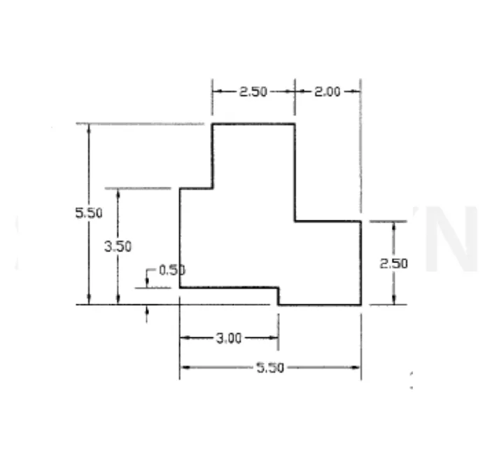 Aim:- To draw the above figure using AutoCADProcedure:-
- open autocad
- new file
- starting point is 'a' ( 0, 0)
- b = 3.0, 0.0
- c = 3.0, -0.5
- d = 5.50, -0.50
- e = 5.50, 2.0
- f =
- g = 8.80, 3.60
- h = 8.80, 0.0
- esc
Result:-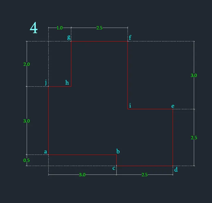
Q.5)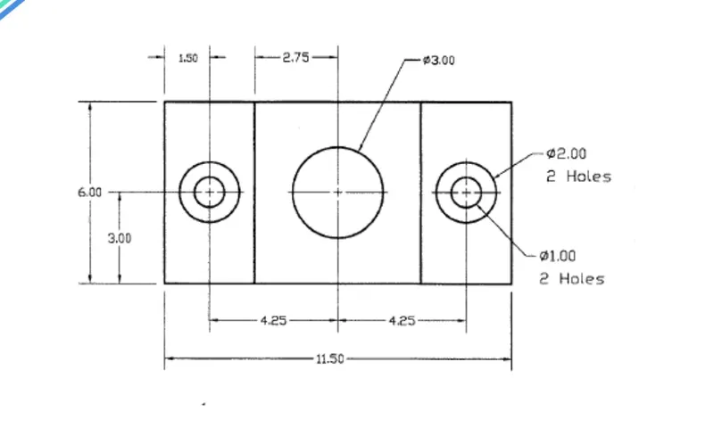
Aim:- To draw the above figure using AutoCADProcedure:-- open a new file using the 'NEW' command
- 'rec' command
- draw a rectangular 'abcd' of 11.5X6.0
- esc
- 'X' command, select rectangular abcd and EXPLODE it.
- esc
- 'O' offset command, select line AD and offset it at distances in right side 3.0 & 8.50 to draw line EF & HG. esc
- again 'O' offset command, select line AB and offset it at distances in upward 3.0 to draw a line and change its property to the dotted line.
- esc
- now mark points i, j, & k as per dimension given to draw a circle.
- circle command, draw two circles of dia 1.0 & 2.0 at point 'i'.
- esc
- copy those two circles at 'i' using the copy command and paste it at 'k'
- esc
- again using the circle command draw a circle of dia 3.00 at 'j'.
- esc
Result:-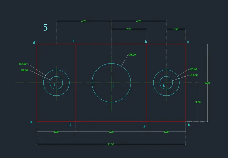
Q.6)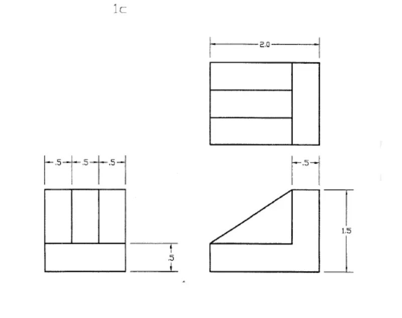
Aim:- To draw the above figure using AutoCAD
Procedure:-- open a new file using the 'NEW' command
- 'rec' command
- draw a rectangular 'abcd' of 1.5 X 1.50
- esc
- 'X' command, select rectangular abcd and EXPLODE it.
- esc
- 'O' offset command, select line AD and offset it two times at distance 0.50.
- esc
- again offset BC at distance 0.5 in upward
- esc
- 'TR' trim command, trim the unrequired line, and the result you can see in the image.
- ecs
- 'L' command, start from point 'f'
- g = 2.0 unit in right side
- h = 1.5 unit in upward direction
- i = 0.5 in left side
- j = 1.0 in downward
- e = 1.5 in leftward
- close
- again line command join 'e' & 'i'.
- esc
- in a similar way draw other parts also.
Result:-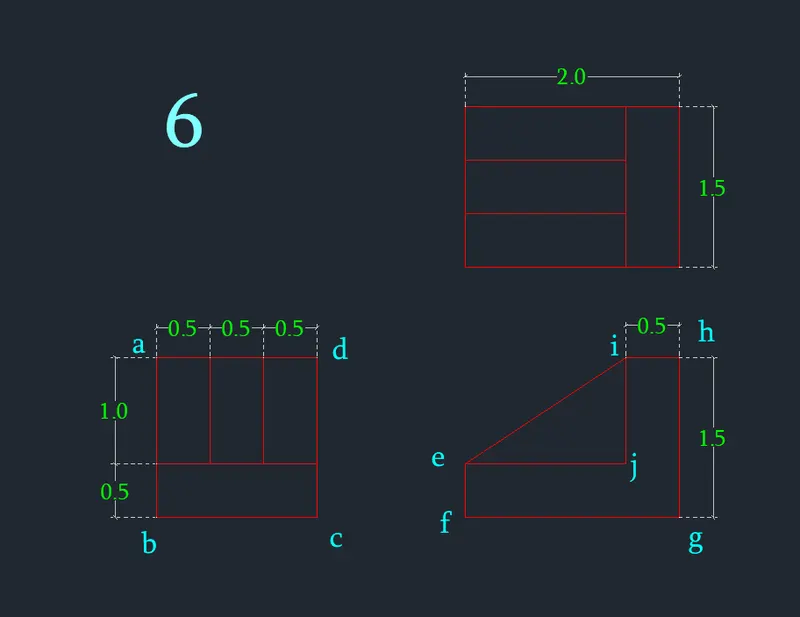 Q.7)
Q.7)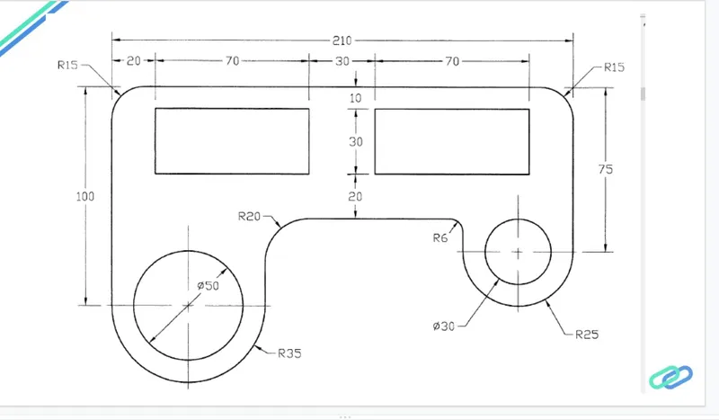
Aim:- To draw the above figure using AutoCADProcedure:-- open a new file using the 'NEW' command
- 'arc' command
- starting point 'a'
- draw arch 'ab' of radius 35
- esc
- 'L' command, start drawing a line from point 'b' to 'e' as per given dimension
- esc
- 'arc' command, draw arch 'ef' of radius 25
- join 'a' & 'f'
- esc
- mark points g, h, i, j using point command
- esc
- draw two circles using circle command of dia 50 & 30 at 'i', & 'j'.
- esc
- now draw of rectangular using 'rec' command of size 70 X 30
- esc
- copy that rectangle and paste it at 'h'
- sec
- 'F' fillet command, sellect radious option & give R15 at 'g' and 'd'.
- esc
- using the same command give R20 at 'a' & R6 at 'f'
- esc
Result:-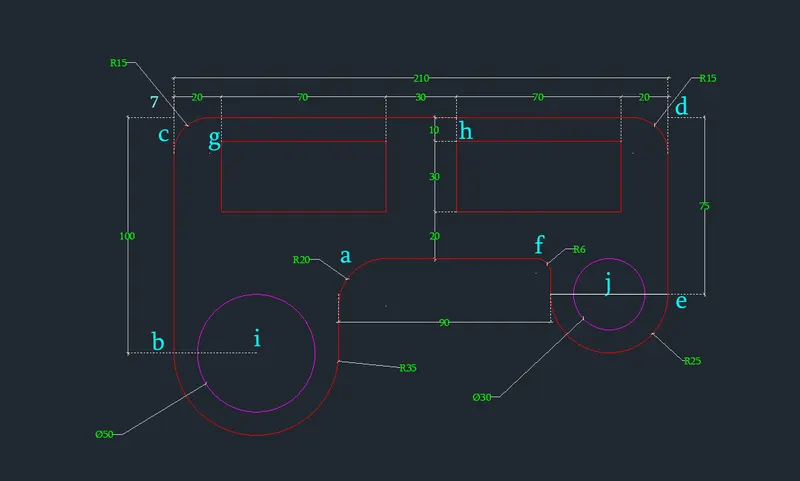
Q.8)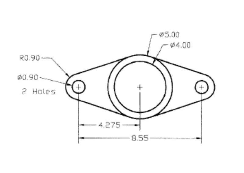
Aim:- To draw the above figure using AutoCADProcedure:-- open AutoCAD new file
- mark three-point 'c', 'a', 'b' at a distance 4.3 each.
- using circle command draw circle at 'a' of R 2.0 & R 2.5
- again at points, c & d make circles of R 0.5 & R 0.9
- esc
- draw tangent lines on both sides.
- using trim command erase unnecessary arch.
Result:-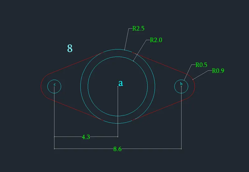
Q.9)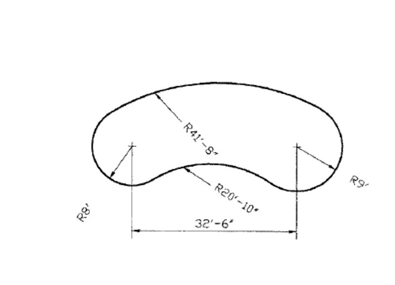
Aim:- To draw the above figure using AutoCADProcedure:-- open AutoCAD new file
- mark two points using point command 'a' & 'b', the distance between those points is 32'-6".
- esc
- using circle command draw two circles at 'a' & 'b' of radius 8' & 9'.
- esc
- go to robbin and select draw circle tangent to tangent and radius
- now draw two circles one is outer nad other is inner of those two circles of radius R41'-8" & R20'-10"
- esc
- using trim command erases the unrequired arch.
- esc
- now give dimension of all arch and circle using different dimension option.
Result:-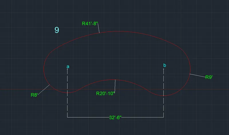 Q.10)
Q.10)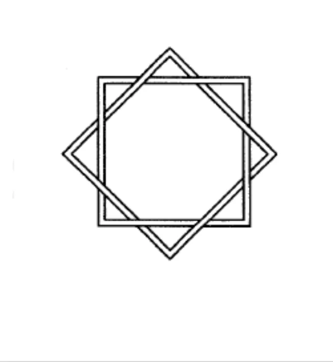 Aim:- To draw the above figure using AutoCADProcedure:-
- open AutoCAD new file
- ''rec' command, draw a rectangle 'abcd' of sides 10.
- esc
- mark point 'e' at the center of rectangle abcd
- esc
- 'O' offset command, offset the rectangle 'abcd' at distance 0.25 toward inside of rectangle abcd
- esc
- now copy the whole thing somewhere else.
- now rotate the copied rectangles at an angle 45 degrees using 'RO' command.
- esc
- now move the rotated rectangles using 'MOVE' command from point 'e' to 'e'
- esc
Result:-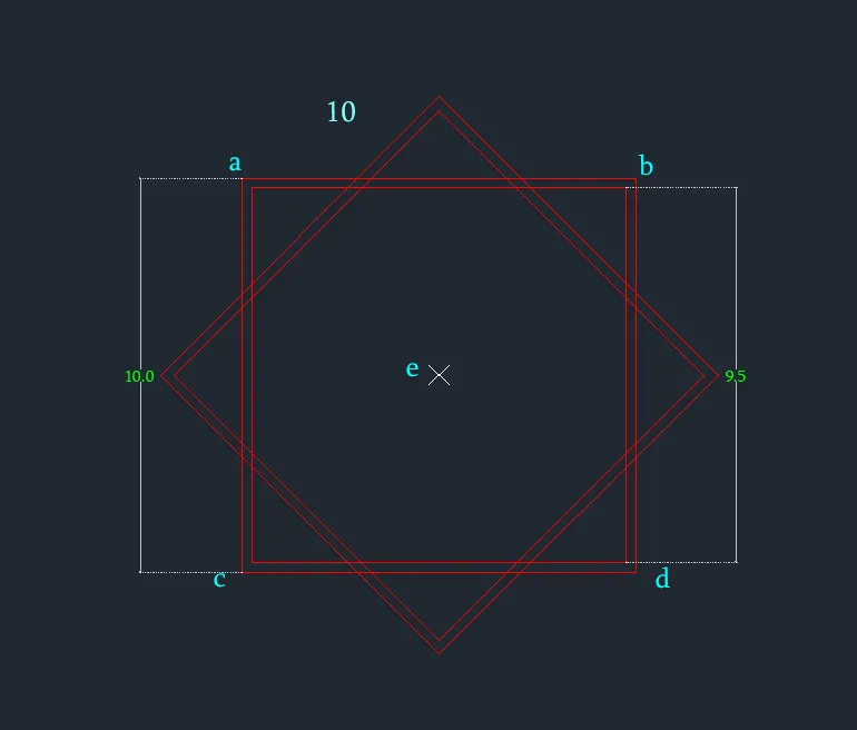 Q.11)
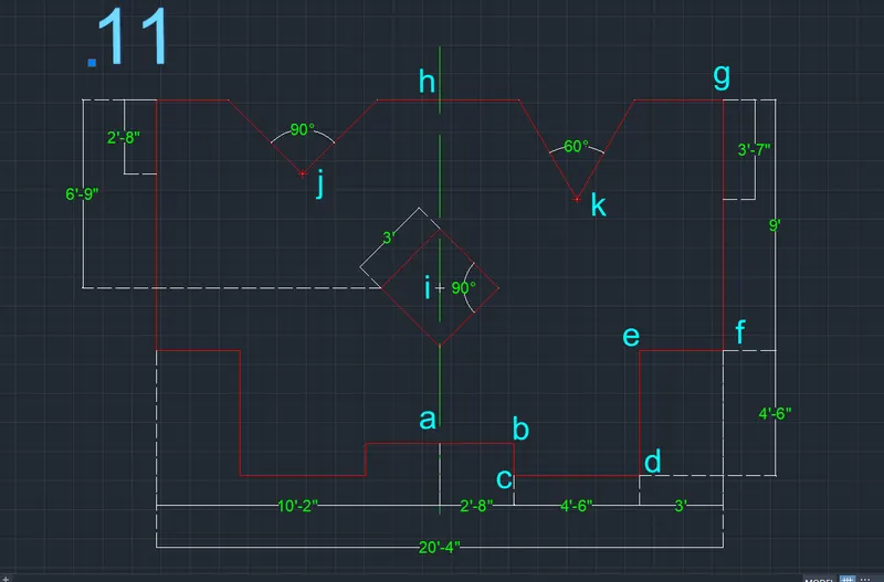
Q.11)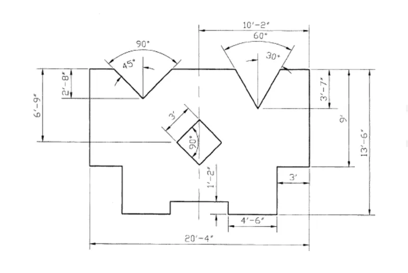 Aim:- To draw the above figure using AutoCADProcedure:-
- open AutoCAD new file
- 'L' command
- start drawing from point 'a' to 'h' as per the given dimension
- esc
- now a select whole thing and mirror it from point 'a' to 'h' using 'MI' command and the main thing is don't erase selected lines.
- esc
- now mark three point 'j', 'k', & 'i' using point command.
- esc
- now draw a rectangle of side 3.0' and rotate it by 45 degrees, after that, move it to point 'i' through the center of that rectangle.
- esc
- line command, start from 'k' at an angle 60 degrees on line HG. and mirror that drawn line (orthomode)
- do the same process at 'j' at 445 degree
- esc
- now erase unrequired lines by using the trim command.
- esc
Result:-