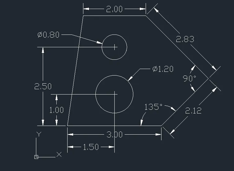
Drafting of various geometries using Chamfer, Fillet tool in AutoCad
1.Decimal
Aim
- Open AutoCad application
- Set units measurement as engineering, angle as decimal degree, angle measure as east, angle direction as clockwise, area as 9x12 inches and close the tab.
- Now enable the dynamic input, right click dynamic input and choose dynamic input settings. Go to pointer input setting and set default to cartesian format.
- Ortho mode is ON
- Enter command line L
- Specify the first point 1,1
- Specify next point : 3 by moving cursor towards right
- Specify next point : @2.12<45
- Specify next point : @135<2.83
- Specify next point : 2 by moving cursor towards left
- Enter close
- Draw a circle at a point 2.5, 2 and diameter of 1.2
- Draw another circle at a point 2.5,3.5 and diameter of 0.8
- Using Dimlinear, Dim aligned and Dim angular mark the dimensions
- Using Chamfer tool
- Enter command line L
- Specify the first point 1,1
- Specify next point : 3 by moving cursor towards right
- Specify next point : 1.499 by moving cursor towards right (assume line A)
- Specify next point : 1.499 by moving cursor upwards (assume line B)
- Specify next point : 2 by moving cursor upwards (assume line C)
- Specify next point : 2 by moving cursor towards left (assume line D)
- Specify next point : 2 by moving cursor towards left
- Enter close
- Enter Chamfer in command
- Select distance
- Enter first distance 1.499, second distance 1.499 and then select the lines
- Press enter
- Similar way using chamfer tool
- Enter first distance 2, second distance 2 and then select the lines
- Press enter
- Now trim off lines A,B,C,D using trim tool
- Press enter
- Draw a circle at a point 2.5, 2 and diameter of 1.2
- Draw another circle at a point 2.5,3.5 and diameter of 0.8
- Using Dimlinear, Dim aligned and Dim angular mark the dimensions
Result
The given diagram is drawn in autocad.
2. Architectural
Aim
To draw the given architectural diagram
Procedure
- Set units to architectural
- Set precision in dimstyle to architectural
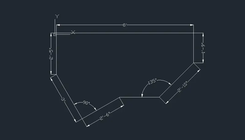
- Enter line L in command
- Specify first point 1,1
- Specify next point 8' by moving cursor towards right
- Specify next point 1'9'' by moving cursor downwards
- Specify next point @2'10''<-135
- Press enter
- Enter line L in command
- Specify first point 1,1
- Specify next point @2'5''<90
- Specify next point @3'<-60
- Specify next point @2'6''<30
- Join the two end points and close
- Using Dimlinear, Dim aligned and Dim angular mark the dimensions
Result
The given architectural diagram is drawn in autocad.
3. Engineering
Aim
To draw the given engineering diagram in autocad.
Procedure
- Enter command UNITS
- Change length type to engineering and precision to 0'-0"
- Enter command DIMSTYLE
- Click on modify
- Change primary units to engineering and and precision to 0'-0.00"
- Click okay and close
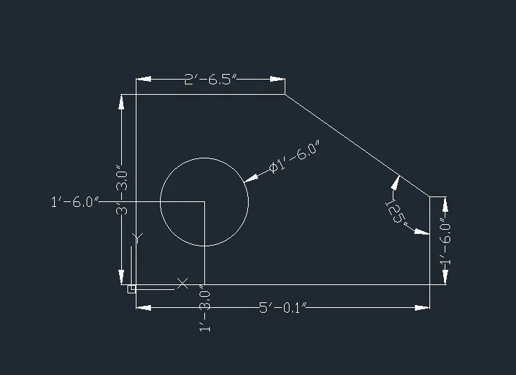
- Enter command line L
- Specify first point 1,1
- Specify next point 5'0.1'' by moving cursor towards right
- Specify next point 1'6'' by moving cursor upward
- Specify next point 1'9'' by moving cursor upward
- Specify next point 2'5.59'' by moving cursor leftside
- Specify next point 2'6.5'' by moving cursor leftside
- Enter close
- Enter Chamfer in command
- Select distance
- Enter first distance 2'5.59'', second distance 1'9'' and then select the lines
- Press enter
- Draw a circle at a distance of 1'3'',1'6'' from point 1,1 with diameter 1'6''
- Using Dimlinear and Dim angular mark the dimensions
Result
The given diagram is drawn in autocad by setting unit in engineering.
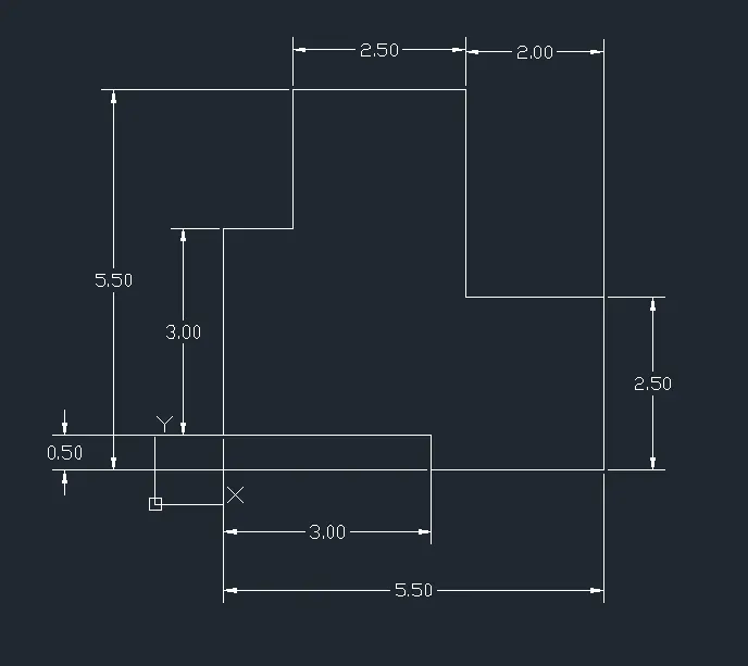
4.
Aim
To draw the given diagram in autocad
Procedure
- Enter command line L
- Specify first point 1,1
- Specify next point 0.5 by moving cursor upward
- Specify next point 3 by moving cursor leftside
- Specify next point 3 by moving cursor upward
- Specify next point 1 by moving cursor rightside
- Specify next point 2 by moving cursor upward
- Specify next point 2.5 by moving cursor rightside
- Specify next point 3 by moving cursor downward
- Specify next point 2 by moving cursor rightside
- Specify next point 2.5 by moving cursor downward
- Specify next point 2.5 by moving cursor leftside
- Press enter
- Using Dimlinear mark the dimensions
Result
Thus the given diagram is drawn in autocad.
5.
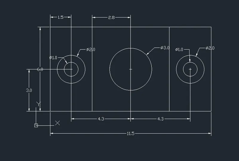
Aim
To draw the given diagram and circles inside
Procedure
- Draw rectangle
- Specify first point 1,1
- Click on dimension and enter length 5.75 and width 6
- Press enter
- Draw circle at point as center 2.5,4 and diameter 2
- At same point as center draw another circle with diameter 1
- Draw circle at point as center 6.5,4 and diameter 3
- Press enter
- Enter mirror
- Select all objects and enter
- Select first, second point of mirror line and create a mirror image
- Press enter
- Trim off unnecessary lines
- Using Dimlinear mark the dimensions
Result
Thus the given diagram and circles are drawn
6.
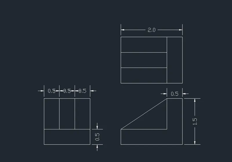
Aim
To draw the given diagram in autocad
Procedure
- Draw rectangle at point 1,1 with length and width as 1.5
- Draw another rectangle at point 1,1.5 with length as 0.5 and width as 1
- Copy this rectangle and make another two rectangles
- Paste it beside one another in the rightside
- Press enter
- Take a point 4,1 and draw rectangle with length 2 and width 1.5
- Enter command line L
- Specify first point as 4,1
- Specify next point 0.5 by moving cursor upward
- Specify next point 1.5 by moving cursor rightside
- Specify next point 1 by moving cursor upward
- Press enter
- Enter chamfer in the command
- Enter the distance
- First distance as 1 and second distance as 1.5
- Select the lines and press enter
- Trim off the lines according to diagram
- Draw rectangle at point 4,3 with length as 2 and width as 1.5
- Draw rectangle at point 4,3 with length as 2 and width as 0.5
- Copy this rectangle and make another two rectangles
- Paste it beside one another in the upperside
- Using Dimlinear mark the dimensions
Result
Thus the given diagram are drawn
7.
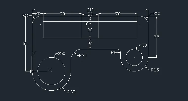
Aim
To draw the given diagram using fillet tool
Procedure
- Enter command line L
- Specify first point 1,1
- Specify next point 100 by moving cursor upwards
- Specify next point 210 by moving cursor rightside
- Specify next point 75 by moving cursor downwards and press enter
- Now draw an arc of radius 25 (diameter 50) using start, end (50) and angle (-180 degree)
- Press enter
- Draw a circle of diameter 30 using center of previous drawn arc and press enter
- Draw a line of length 15 by moving cursor upwards
- Specify next point 90 by moving cursor leftside
- Specify next point 40 by moving cursor downward
- Now draw an arc of radius 35 (diameter 70) using start, end (70) and angle (-180 degree)
- Press enter
- Draw a circle of diameter 50 using center of previous drawn arc and press enter
- Draw two rectangles of length 70 and width 30 at a distance x=20,y=10 at the top of diagram and press enter
- Using fillet tool draw an arc of radius 15 (at @0,100) and press enter
- Using fillet tool draw an arc of radius 15 (at @210,100) and press enter
- Using fillet tool draw an arc of radius 6 (at @160,40) and press enter
- Using fillet tool draw an arc of radius 20 (at @70,40) and press enter
- After fillet, using trim tool trim off the edge lines
- Using Dimlinear, Dimradius and Dimdiameter mark the dimensions
Result
The given diagram is drawn using fillet tool
8.
Aim
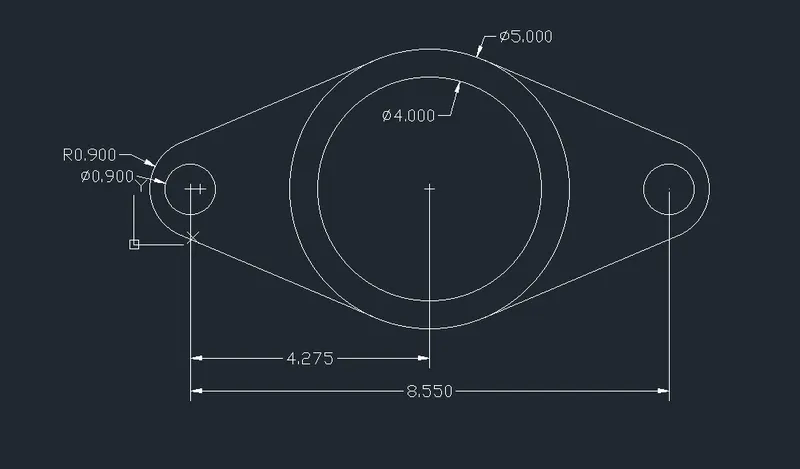
To draw the given diagram using circle and fillet tool
Procedure
- Draw a circle of diameter 0.9 (circle 1)
- Draw two lines of length 4.275 and 8.55 from the center of circle 1
- At a distance of 4.275 from the center of circle 1 draw two another circles of diameter 5 (circle 3)and 4
- At a distance of 8.55 from the center of circle 1 draw a circle of radius 0.9 (circle 2)
- Draw a line of 1.8 length which is tangent to circle 1(on left side)
- Draw a line of 1.8 length which is tangent circle 2 (on right side)
- Draw an arc using start end and radius (0.9) using end points of line 1.8 on both sides of diagram
- Draw tangent from circle 3 to left side arc using line tool ( specify first point : hold shift+right click, click on tangent)
- Draw tangent from circle 3 to right side arc using line tool ( specify first point : hold shift+right click, click on tangent)
- After drawing tangent trim off the remaining arc
- Remove lines 1.8, 4.275 and 8.55
- Using Dimlinear, Dimradius and Dimdiameter mark the dimensions
Result
Thus the given diagram is dtrawn using circle and fillet tool
9.
Aim
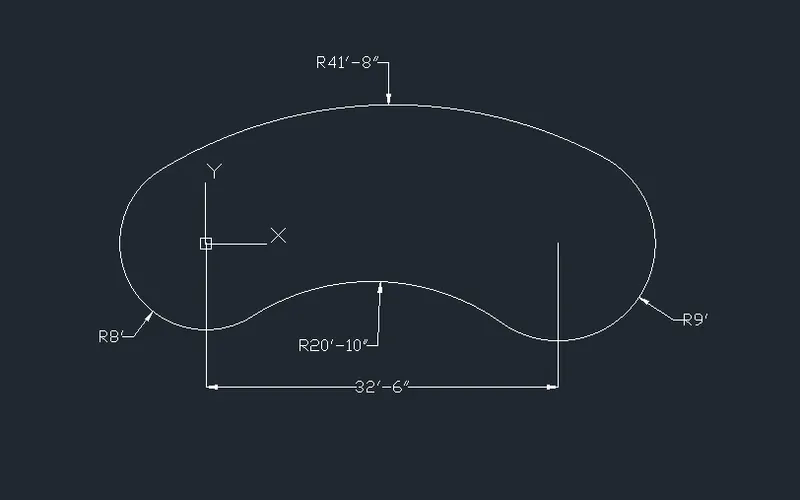
To draw the given diagram using circle tangent tool
Procedure
- Set units to architectural
- Set precision in dimstyle to architectural
- Draw a circle of radius 8' from point 1,1 (circle 1)
- Press enter
- Draw another circle of radius 9' from at a distance of 32'6'' from start point (circle 2)
- Press enter
- Now draw a circle using tangent, tangent, radius with radius 41'8'' (selecting tangents of circle 1, circle 2)
- Press enter
- Now draw another circle using tangent, tangent, radius with radius 20'10'' (selecting tangents of circle 1, circle 2)
- Press enter
- Using trim tool, trim off extra according to diagram
- Using Dimlinear and Dimradius mark the dimensions
Result
Thus the given diagram is drawn using circle tangent tool
10.
Aim
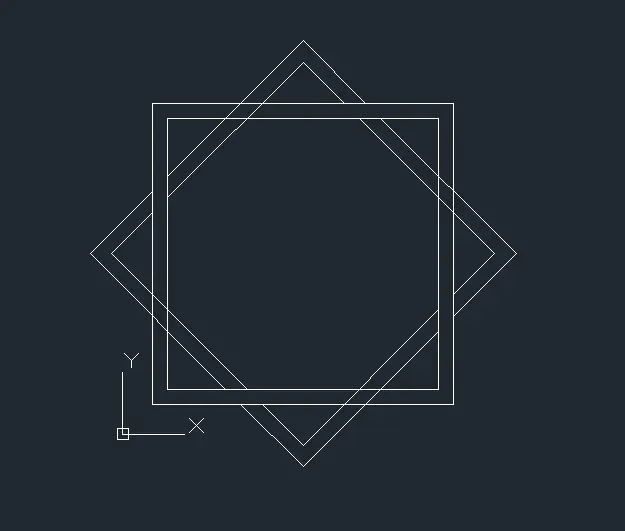
To draw the given diagram using offset command
Procedure
- Enter REC in command
- Specify first point 1,1
- Draw a rectangle with length and width as 10
- Press enter
- Enter OFFSET in the command and offset distance of 0.5
- Select the rectangle and press enter
- Select Polygon
- Enter number of sides of 4
- Specify center of polygon at 6,6
- Then enter the option circumscribed
- Specify the radius of circle @5<45
- Press enter
- Enter OFFSET in the command and offset distance of 0.5
- Select the rectangle and press enter
- Using trim tool, trim off the lines according to diagram
- Press enter
Result
Thus the given diagram is drawn using offset command
11.
Aim
To draw the given diagram using triangle tool
Procedure
- Set units to engineering
- Set precision in dimstyle to engineering
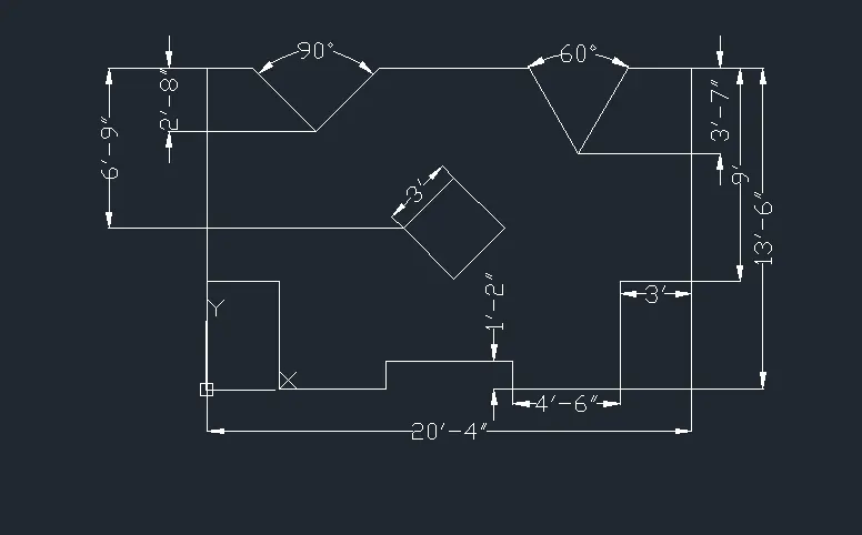
- Draw a rectangle of length 20'4'' and width 13'6" from point 1,1
- Draw a rectangle of length 3' and width 4'6" from point 1,1
- Draw a rectangle of length 3' and width 4'6" from point 20'5",1 towards left side
- Draw a rectangle of length 5'4 and width 1'2" from point 7',7''
- Draw a rectangle of length 3' and width 3' from a distance of 6'9'' from the top with an angle of rotation 45
- Draw a triangle of 45 degree with height and base of 2'8" at a distance of 3' from top left side of diagram
- Using mirror tool, similar triangle is made on other side
- Draw a triangle of 30 degree with height 2'0.82" and base of 3'7" at a distance of 3' from top right side of diagram
- Using mirror tool, similar triangle is made on other side
- Using trim tool, trim off the lines according to diagram
- Using Dimlinear and Dim angular mark the dimensions
Result
Thus the given diagram is drawn using triangle tool