Drafting of various geometries using Chamfer, Fillet tool in AutoCad
Question :- Drafting of various geometries using Chamfer, Fillet tool in AutoCad
Answer =
AIM :- Drafting of various geometries using Chamfer, Fillet tool in AutoCad'
INTRODUCTION :- AutoCad is consists of various tools and functions for drawing and drafting.Its has also the modification tools so by using the such modification tools like Chamfer, Fillet, rotate, copy, move, mirror, trim, offset, object snap, Extend and join
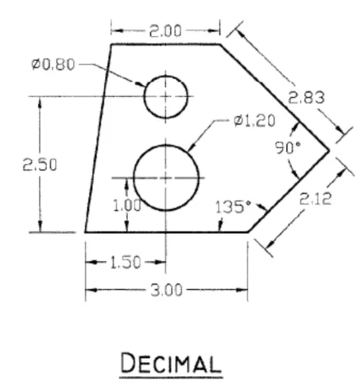
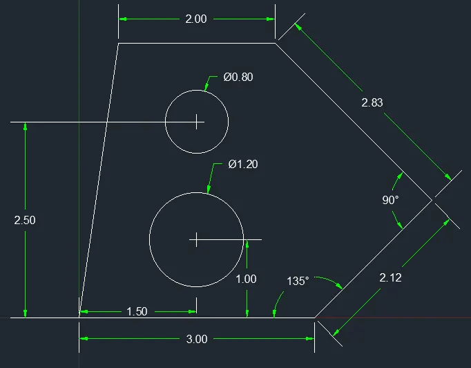
1.Drafting the given geometry using decimal unit system
PROCEDURE =
- Enter UNITS command in the command tool bar
- In the drawing units dialod box Select Decimal Function and below that choose 0.00 precision
- Select Meters in the insersion scale
- Select the line tool by entering LINE command in the tool bar
- Specify the first line as 0,0 in the command tool bar
- Specify the coordinate of next point as @3.00<0 in the command toolbar
- Specify the coordinate of next point as @2.12<45 in the command toolbar
- Specify the coordinate of next point as @2.83<135 in the command toolbar
- Specify the coordinate of next point as @-2.00<0 in the command toolbar
- Click Close on the command tool bar
- Select the circle tool by entering CIRCLE command in the tool bar
- Specify the center point of circle as 1.50,1.00 in the comand tool bar
- Select the diameter option in the command line and specify the diameter as 1.20
- Select the circle tool by entering CIRCLE command in the tool bar
- Specify the center point of circle as 1.50,2.50 in the comand tool bar
- Select the diameter option in the command line and specify the diameter as 0.80
- Type DST command in the command tool bar
- Give the color to the main lines and extension lines
- Under the Symbols and arrows and Text option give specific dimension as per requirements in the drawing
- Gie specific Text height and arrow size as per requirements in the drawing
- Then click on OK THen click Set current option and close the dialog box
RESULT :-
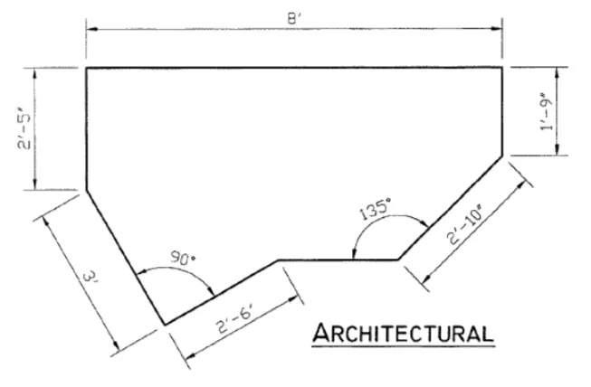
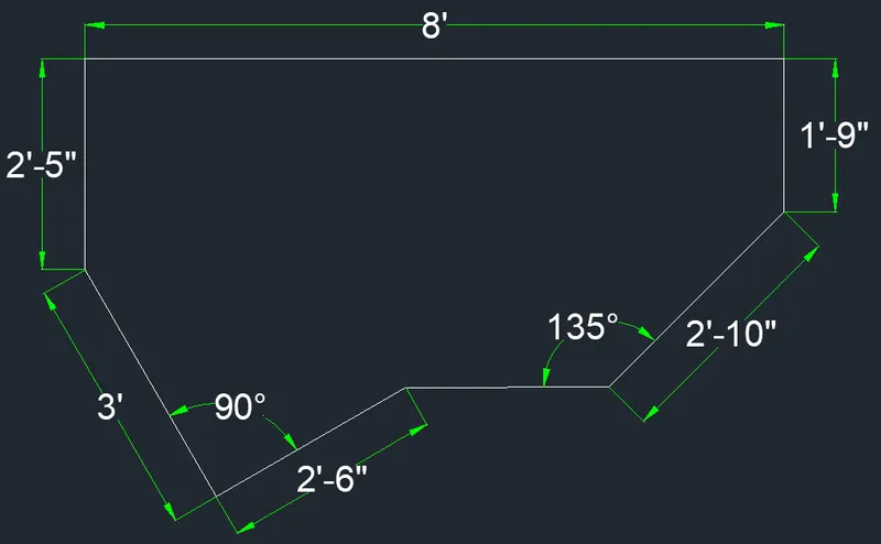
2.Drafting the given geometry using Architectural unit system
PROCEDURE =
- Enter UNITS command in the command tool bar
- In the drawing units dialod box Select Architecture Function and below that choose 0'-0" precision
- Select Inches in the insersion scale
- Select the line tool by entering LINE command in the tool bar
- Specify the first line as 10,10 in the command tool bar
- Specify the coordinate of next point as @2'-10"<45 in the command toolbar
- Specify the coordinate of next point as @0,1'-9" in the command toolbar
- Specify the coordinate of next point as @-8',0 in the command toolbar
- Specify the coordinate of next point as @0,-2'5" in the command toolbar
- Specify the coordinate of next point as @3'<300 in the command toolbar
- Specify the coordinate of next point as @2'6"<30 in the command toolbar
- Click Close on the command tool bar
- Type DST command in the command tool bar
- Give the color to the main lines and extension lines
- Under the Symbols and arrows and Text option give specific dimension as per requirements in the drawing
- Give specific Text height and arrow size as per requirements in the drawing
- Then click on OK THen click Set current option and close the dialog box
RESULT :-
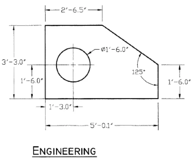
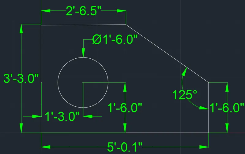
3..Drafting the given geometry using Engineering unit system
PROCEDURE =
- Enter UNITS command in the command tool bar
- In the drawing units dialod box Select Engineering Function and below that choose 0'-0.0" precision
- Select Inches in the insersion scale
- Select the line tool by entering LINE command in the tool bar
- Specify the first line as 0'-0.0",0'-0.0" in the command tool bar
- Specify the coordinate of next point as @5'0.1",0'-0.0" in the command toolbar
- Specify the coordinate of next point as @0'-0.0",3'3.0" in the command toolbar
- Specify the coordinate of next point as @-5'0.1,0'-0.0" in the command toolbar
- Click Close on the command tool bar
- Select CHAMFER command in the command tool bar
- Select the Angle option in the command tool bar
- Specify the chamfer length for te first line as 1'6.0"
- Specify the angle as 125
- Select the chamfer line and then select the Distance option on the command tool bar
- Speify the first chamfer distance as 1'9.0"
- Speify the second chamfer distance as 2'5.6"
- Then select the second line
- Select the circle tool by entering CIRCLE command in the tool bar
- Specify the center point of circle as 1'3.0",1'6.0" in the comand tool bar
- Select the diameter option in the command line and specify the diameter as 1'6.
- Type DST command in the command tool bar
- Give the color to the main lines and extension lines
- Under the Symbols and arrows and Text option give specific dimension as per requirements in the drawing
- Give specific Text height and arrow size as per requirements in the drawing
- Then click on OK THen click Set current option and close the dialog box
RESULT :-
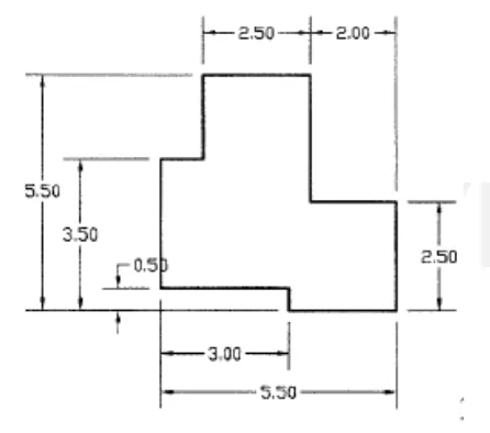
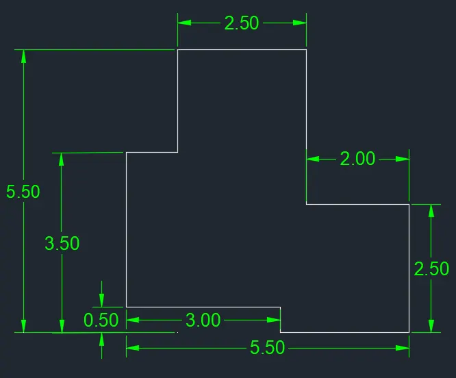
4.Drafting the given geometry using AutoCad tools
PROCEDURE =
- Enter UNITS command in the command tool bar
- In the drawing units dialod box Select Decimal Function and below that choose 0.00 precision
- Select Meters in the insersion scale
- Select the line tool by entering LINE command in the tool bar
- Specify the first line as 0,0 in the command tool bar
- Specify the coordinate of next point as @3.00,0.00 in the command toolbar
- Specify the coordinate of next point as @0.00,-0.50 n the command toolbar
- Specify the coordinate of next point as @2.50,0.00 n the command toolbar
- Specify the coordinate of next point as @0.00,2.50 in the command toolbar
- Specify the coordinate of next point as @-2.00,0.00in the command toolbar
- Specify the coordinate of next point as @0.00,3.00 in the command toolbar
- Specify the coordinate of next point as @-2.50,0.00 in the command toolbar
- Specify the coordinate of next point as @0.00,-2.00 in the command toolbar
- Specify the coordinate of next point as @-1.00,0.00 in the command toolbar
- Click Close on the command tool bar
- Type DST command in the command tool bar
- Give the color to the main lines and extension lines
- Under the Symbols and arrows and Text option give specific dimension as per requirements in the drawing
- Give specific Text height and arrow size as per requirements in the drawing
- Then click on OK THen click Set current option and close the dialog box
RESULT :-
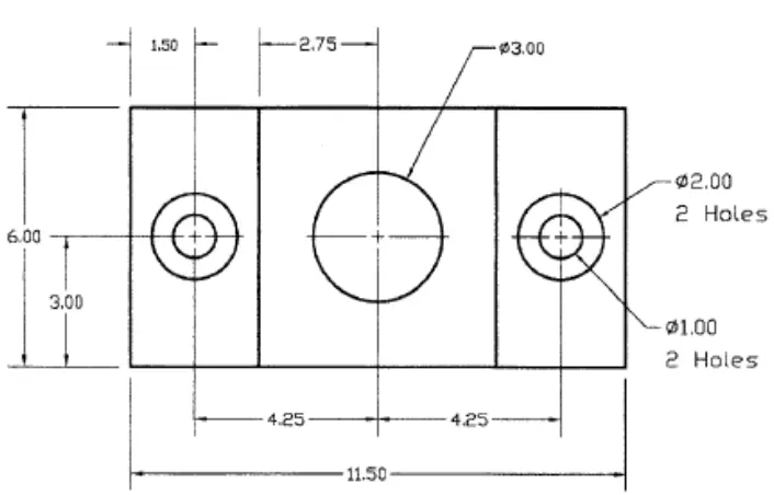
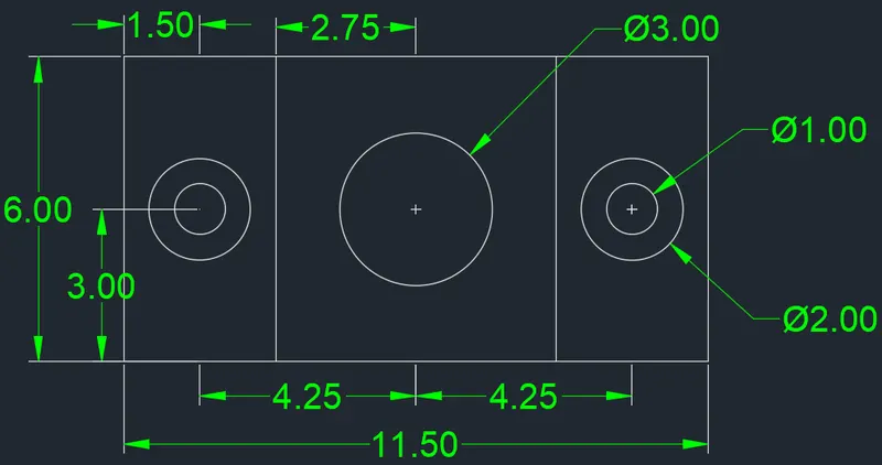
5.Drafting the given geometry using AutoCad tools
PROCEDURE =
- Enter UNITS command in the command tool bar
- In the drawing units dialod box Select Decimal Function and below that choose 0.00 precision
- Select Meters in the insersion scale
- Select the line tool by entering LINE command in the tool bar
- Specify the first line as 0,0 in the command tool bar
- Specify the coordinate of next point as @11.50,0.00 in the command toolbar
- Specify the coordinate of next point as @0.00,6.00 in the command toolbar
- Specify the coordinate of next point as @-11.50,0.00 in the command toolbar
- Click Close on the command tool bar
- Select the offset tool by entering OFFSET command in the tol bar
- Enter 3.00 as offset distance in the command line
- select the line that should be offset and click on the desired side repeat the same for the right line of the drawing
- Press Esc to cancel the offset command
- Select the circle tool by entering CIRCLE command in the tool bar
- Specify the center point of circle as 1.50,3.00 in the comand tool bar
- Select the diameter option in the command line and specify the diameter as 2.00
- Select the offset tool by entering OFFSET command in the tol bar
- Enter 0.50 as offset distance in the command line
- Select the left circle and click on inside the circle
- press Esc to cancel the offset command
- Select the circle tool by entering CIRCLE command in the tool bar
- Specify the center point of circle as 5.75,3.00 in the comand tool bar
- Select the diameter option in the command line and specify the diameter as 3.00
- Select the circle tool by entering CIRCLE command in the tool bar
- Specify the center point of circle as 10.00,3.00 in the comand tool bar
- Select the diameter option in the command line and specify the diameter as 2.00
- Select the offset tool by entering OFFSET command in the tol bar
- Enter 0.50 as offset distance in the command line
- Select the left circle and click on inside the circle
- press Esc to cancel the offset command
- Type DST command in the command tool bar
- Give the color to the main lines and extension lines
- Under the Symbols and arrows and Text option give specific dimension as per requirements in the drawing
- Give specific Text height and arrow size as per requirements in the drawing
- Then click on OK THen click Set current option and close the dialog box
RESULT :-
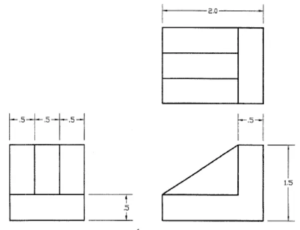
6.Drafting the given geometry using AutoCad tools
PROCEDURE =
- Enter UNITS command in the command tool bar
- In the drawing units dialod box Select Decimal Function and below that choose 0.00 precision
- Select Meters in the insersion scale
- Select the line tool by entering LINE command in the tool bar
- Specify the first line as 4.5,2.5 in the command tool bar
- Specify the coordinate of next point as @2.0,0.0 in the command toolbar
- Specify the coordinate of next point as @0.0,1.5 in the command toolbar
- Specify the coordinate of next point as @-2.0,0.0 in the command toolbar
- Click Close on the command tool bar
- Select the offset tool by entering OFFSET command in the tool bar
- Enter 0.5 as offset distance in the command line
- select the right most line that should be offset and click on the desired side repeat the same for the upper line of the drawing
- Press Esc to cancel the offset command
- Select the Trim tool by entering TR command in the tol bar
- Select the lines that should be trim
- press Esc to cancel the Trim option
- Select the line tool by entering LINE command in the tool bar
- Specify the first line as 4.5,0.0 in the command tool bar
- Specify the coordinate of next point as @2.0,0.0 in the command toolbar
- Specify the coordinate of next point as @0.0,1.5 in the command toolbar
- Specify the coordinate of next point as @-0.5,0.0 in the command toolbar
- Specify the coordinate of next point as @-1.5,-1.0 in the command toolbar
- Click Close on the command tool bar
- Select the line tool by entering LINE command in the tool bar
- Specify the first line as 4.5,0.5 in the command tool bar
- Specify the coordinate of next point as @1.5,0.0 in the command toolbar
- Specify the coordinate of next point as @0.0,1.0 in the command toolbar
- Press Esc to cancel the line tool
- Select the line tool by entering LINE command in the tool bar
- Specify the first line as 0.0,0.0 in the command tool bar
- Specify the coordinate of next point as @1.5,0.0 in the command toolbar
- Specify the coordinate of next point as @0.0,1.5 in the command toolbar
- Specify the coordinate of next point as @-1.5,0.0 in the command toolbar
- Click Close on the command tool bar
- Select the offset tool by entering OFFSET command in the tool bar
- Enter 0.5 as offset distance in the command line
- select the right most line that should be offset and click on the desired side repeat the same for them bottom line of the drawing
- Press Esc to cancel the offset command
- Select the Trim tool by entering TR command in the tol bar
- Select the lines that should be trim
- press Esc to cancel the Trim option
- Type DST command in the command tool bar
- Give the color to the main lines and extension lines
- Under the Symbols and arrows and Text option give specific dimension as per requirements in the drawing
- Give specific Text height and arrow size as per requirements in the drawing
- Then click on OK THen click Set current option and close the dialog box
RESULT :-
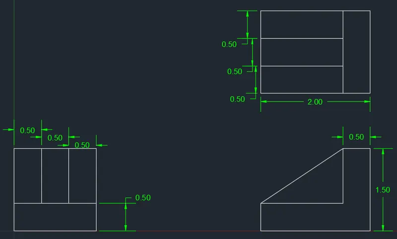
7.Drafting the given geometry using AutoCad tools
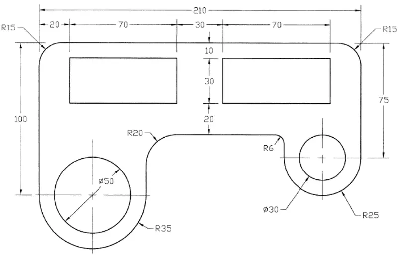
PROCEDURE =
- Enter UNITS command in the command tool bar
- In the drawing units dialod box Select Decimal Function and below that choose 0.00 precision
- Select Meters in the insersion scale
- Select the line tool by entering LINE command in the tool bar
- Specify the first line as 0,0 in the command tool bar
- Specify the coordinate of next point as @0,100 in the command toolbar
- Specify the coordinate of next point as @210,0 in the command toolbar
- Specify the coordinate of next point as @0,-75 in the command toolbar
- Press Esc to cancel the line tool
- Select the Fillet tool by entering FILLET command in the tool bar
- Select the line of length 100 units
- Click on the Radius option in the command tool bar and specify the radius as 15
- Select the second line of length 210 units
- Again Select the Fillet tool by entering FILLET command in the tool bar
- Select the line of length 75 units
- Click on the Radius option in the command tool bar and specify the radius as 15
- Select the second line of length 210 units
- Select the line tool by entering LINE command in the tool bar
- Specify the first line as 0,0 in the command tool bar
- Specify the coordinate of next point as @70,0 in the command toolbar
- press Esc to cancel the line tool
- Select the line tool by entering LINE command in the tool bar
- Specify the first line as 210,25 in the command tool bar
- Specify the coordinate of next point as @-50,0 in the command toolbar
- press Esc to cancel the line tool
- Select the circle tool by entering CIRCLE command in the tool bar
- Specify the center point of circle as mid -point in the line of length 70 Units
- Select the diameter option in the command line and specify the diameter as 50
- Select the circle tool by entering CIRCLE command in the tool bar
- Specify the center point of circle as the mi point of the line length 50 units
- Select the diameter option in the command line and specify the diameter as 30
- Select the Arc tool by ebtering the ARC command in the command tool bar
- Specify the first point of the arc of 70 units circle select the End option in the command tool bar
- Specify the end point of the arc of 70 units circle select the End option in the command tool bar
- Select the radius option in the command line specify the radius as the 35
- Again Select the ARc tool by ebtering the ARC command in the command tool bar
- Specify the start point of arc as the start point of length 50 units select the End option in the command tool bar
- Specify the end point of the arc of 50 units circle select the End option in the command tool bar
- Select the radius option in the command line specify the radius as the 25
- Select the retangle tool by entering Rectang command in the tool bar
- Specify the first point as 20,60 in the command tool bar
- Select dimension of retangle as 70 and 30 then click Enter button
- Select the Mirror tool by entering the MIRROR command in the tool bar
- Select the Rectangle to mirror and click Enter
- Select the fisrt point of mirror line of 210 units then select second point of mirror line and click NO in the Erase source object
- Select the line tool by entering LINE command in the tool bar
- Specify the first point as corner of right side rectangle
- Specify the coordinate of next point as @0,-20 in the command toolbar
- Press Esc to cancel the line tool
- Select the line tool again by entering LINE command in the tool bar
- draw the horizontal ortho line with respect to the line
- Press Esc to cancel the line tool
- Select the line tool by entering LINE command in the tool bar
- Draw the lines join with respect to arc
- Press Esc to cancel the line tool
- Trim the unwanted lines
- Select the Fillet tool by entering FILLET command in the tool bar
- Click on the Radius option in the command tool bar and specify the radius as 20
- Select the two lines where fillet is required
- Select the Fillet tool by entering FILLET command in the tool bar
- Click on the Radius option in the command tool bar and specify the radius as 6
- Select the two lines where fillet is required
- Give the color to the main lines and extension lines
- Under the Symbols and arrows and Text option give specific dimension as per requirements in the drawing
- Give specific Text height and arrow size as per requirements in the drawing
- Then click on OK THen click Set current option and close the dialog box
RESULT :-
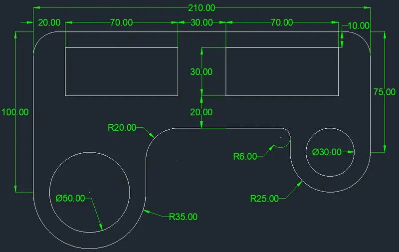
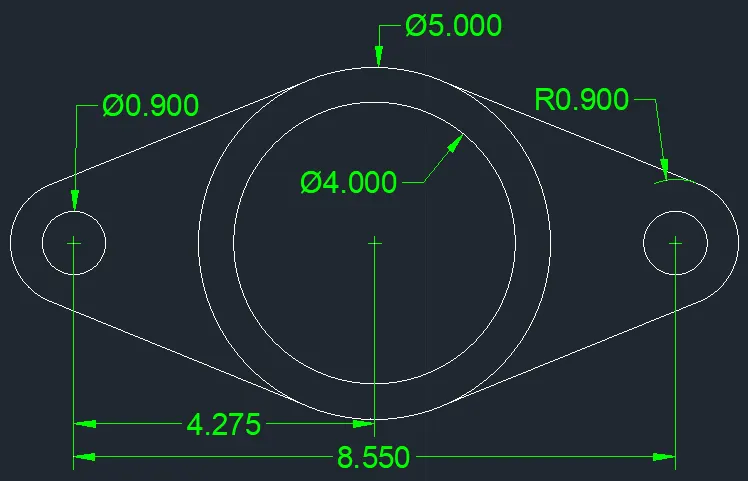
8.Drafting the given geometry using AutoCad tools
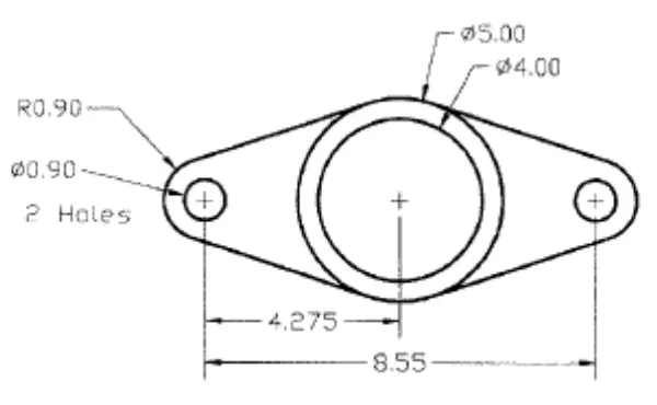
PROCEDURE =
- Enter UNITS command in the command tool bar
- In the drawing units dialod box Select Decimal Function and below that choose 0.000 precision
- Select Meters in the insersion scale
- Select the line tool by entering LINE command in the tool bar
- Specify the first line as 5,5 in the command tool bar
- Specify the coordinate of next point as @8.55,0.0 in the command tool bar
- press Esc to cancel the line tool
- Select the circle tool by entering CIRCLE command in the tool bar
- Specify the center point of circle as mid -point in the line
- Select the diameter option in the command line and specify the diameter as 5.00
- Select the offset tool by entering OFFSET command in the tool bar
- Enter 0.500 as offset distance in the command line
- Select the circle of diameter 5 units and click inside the circle
- Press Esc to cancel the offset command
- Select the circle tool by entering CIRCLE command in the tool bar
- Specify the center point of circle as start -point in the line of length 8.55 units
- Select the diameter option in the command toolbar and specify the diameter as 0.90
- Select the circle tool by entering CIRCLE command in the tool bar
- Specify the center point of circle as end -point in the line of length 8.55 units
- Select the diameter option in the command toolbar and specify the diameter as 0.90
- Select the circle tool by entering CIRCLE command in the tool bar
- Specify the center point of circle as start -point in the line of length 8.55 units created previously
- specify the Radius as 0.90
- Select the circle tool by entering CIRCLE command in the tool bar
- Specify the center point of circle as end -point in the line of length 8.55 units created previously
- specify the Radius as 0.90
- Enter OSNAP in the command line In the drafting setting you have to sekect the tangent command on
- Select the line tool by entering LINE command in the tool bar
- Draw a line joining to a tangent points
- Press Esc to cancel the line tool and repeat the procedure to all four tangents
- Select the Trim tool by entering TR command in the tol bar
- Select the lines that should be trim
- press Esc to cancel the Trim option
- Type DST command in the command tool bar
- Give the color to the main lines and extension lines
- Under the Symbols and arrows and Text option give specific dimension as per requirements in the drawing
- Give specific Text height and arrow size as per requirements in the drawing
- Then click on OK THen click Set current option and close the dialog box
RESULT :-
9.Drafting the given geometry using AutoCad tools
PROCEDURE =
- Enter UNITS command in the command tool bar
- In the drawing units dialod box Select Architecture Function and below that choose 0'-0" precision
- Select Inches in the insersion scale
- Select the line tool by entering LINE command in the tool bar
- Specify the first line as 10,10 in the command tool bar
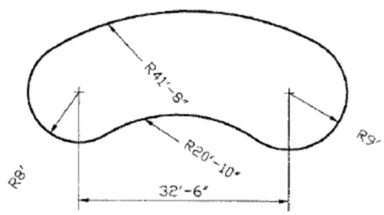
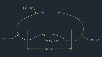
- Specify the coordinate of next point as @32'6',0'00" in the command tool bar
- press Esc to cancel the line tool
- Select the circle tool by entering CIRCLE command in the tool bar
- Specify the center point of circle as start -point in the line of length 32'6" units
- specify the radius as 8'
- Select the circle tool by entering CIRCLE command in the tool bar
- Specify the center point of circle as End -point in the line of length 32'6" units
- specify the radius as 9'
- Select the circle tool by entering CIRCLE command in the tool bar
- Specify the center point of circle as centre of the circle of radius 8'
- specify the radius as 33'8"
- Select the circle tool by entering CIRCLE command in the tool bar
- Specify the center point of circle as centre of the circle of radius 9'
- specify the radius as 32'8"
- Specify the the centre of the circle at the point of intersection of the circle of radius 32'8' and 33'8"
- specify the radius of the circle as 41'8"
- Select the circle tool by entering CIRCLE command in the tool bar
- Select the tan tan radius option in the command tool bar
- Click on first and second circle and specify the radius of the circle as 20'10"
- Select the Trim tool by entering TR command in the tol bar
- Select the lines that should be trim
- press Esc to cancel the Trim option
- Type DST command in the command tool bar
- Give the color to the main lines and extension lines
- Under the Symbols and arrows and Text option give specific dimension as per requirements in the drawing
- Give specific Text height and arrow size as per requirements in the drawing
- Then click on OK THen click Set current option and close the dialog box
RESULT :-
10.Drafting the given geometry using AutoCad tools
PROCEDURE =
- Enter UNITS command in the command tool bar
- In the drawing units dialod box Select Decimal Function and below that choose 0.00 precision
- Select Meters in the insersion scale
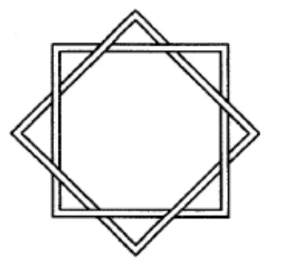
- Select the Rectangle tool by entering RECTANG command in the tool bar
- Specify the length and width of rectangle and click enter
- Select the Offset tool by entering OFFSET command in the command tool bar
- Enter 0.5 as offset distance in the command tool bar
- Select the rectanglre of the size 10 x10 then click inside the rectangle
- Press Esc to cancel the offset command
- Select the copy tool by entering COPY command in the tool bar
- select the object and after its base point and click enter
- Then
- Select the Rotate tool by entering ROTATE command in the tool bar
- Select the copied object and specify the base point
- Specify the angle 45
- Select the move tool by entering MOVE command in the tool bar
- then move the object in the specific direction
- Select the Trim tool by entering TR command in the tol bar
- Select the lines that should be trim
- press Esc to cancel the Trim option
RESULT :-

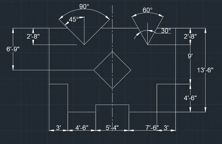
11.Drafting the given geometry using AutoCad tools
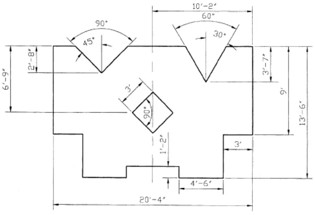
PROCEDURE =
- Enter UNITS command in the command tool bar
- In the drawing units dialod box Select Engineering Function and below that choose 0'-0" precision
- Select Inches in the insersion scale
- Select the line tool by entering LINE command in the tool bar
- Specify the first line as 0'-0",0'-0" in the command tool bar
- Specify the coordinate of next point as @-3',0' in the command toolbar
- Specify the coordinate of next point as @0',-9' in the command toolbar
- Specify the coordinate of next point as @3',0' in the command toolbar
- Specify the coordinate of next point as @0',-4'6" in the command toolbar
- Specify the coordinate of next point as @4'6",0' in the command toolbar
- Specify the coordinate of next point as @0',1'2" in the command toolbar
- Specify the coordinate of next point as @5'4",0' in the command toolbar
- Specify the coordinate of next point as @0',-1'2" in the command toolbar
- Specify the coordinate of next point as @4'6",0' in the command toolbar
- Specify the coordinate of next point as @0',-4'6" in the command toolbar
- Specify the coordinate of next point as @3',0' in the command toolbar
- Specify the coordinate of next point as @0',9' in the command toolbar
- Specify the coordinate of next point as @-3',0' in the command toolbar
- Press Esc to cancel the line command
- Click on the polar tracking and select the 30,60,90 from the list
- Select the line tool by entering LINE command in the tool bar
- select the first point at b then pointing the cursor downword to a length 3'7"
- then pointing the the cursor toward the left of drawing
- Press Esc to cancel the line tool
- Select the mirror tool by entering the MIRROR command in the command tool bar
- Select the object and click enter
- Select first point and second of mirror line and click NO in the erase source object
- Click on the polar tracking and select the 45,90,135 from the list
- Select the line tool by entering LINE command in the tool bar
- select the first point at a then pointing the cursor downword to a length 2'8"
- then pointing the the cursor toward the left of drawing over length of 3'
- Press Esc to cancel the line tool
- Select the mirror tool by entering the MIRROR command in the command tool bar
- Select the object and click enter
- Select first point and second of mirror line and click NO in the erase source object
- Select the line tool and join the two open ends
- Press Esc to cancel the line tool
- Select the line tool and draw lines bisecting both the angles
- Press Esc to cancel the line tool
- Select the Trim tool by entering TR command in the tol bar
- Select the lines that should be trim
- press Esc to cancel the Trim option
- select the line tool and draw aline from the mid point of base line that divides in two parts
- Press Esc to cancel the line tool
- Select the Rectangle tool by entering RECTANG command in the tool bar
- Specify the first point as 7'2",9' in the command tool bar
- Specify the length 3' and width 3' of rectangle and click enter
- Select the Rotate tool by entering ROTATE command in the tool bar
- Select the ractangle object and specify the base point
- Specify the angle 45 about the middle line
- Erase the unwanted lines
- Give the color to the main lines and extension lines
- Under the Symbols and arrows and Text option give specific dimension as per requirements in the drawing
- Give specific Text height and arrow size as per requirements in the drawing
- Then click on OK THen click Set current option and close the dialog box
RESULT :-