Creating a Floor plan, Footing detail and Isometric view using AutoCad
Question :- Creating a Floor plan, Footing detail and Isometric view using AutoCad
Answer =
Aim :- To create the given Floor plan, footing details and isometric view using AutoCad
Introduction :- The main objejective of this assignment is that the cross section of Load Bearing wall over spread footing, Cross section of isolated footing, line diagram of two bedroom building , cross section of Load Bearing wall showing foundation details,Isometric views of steps, Isometric views of gable wall with the help of the various tools of AutoCad
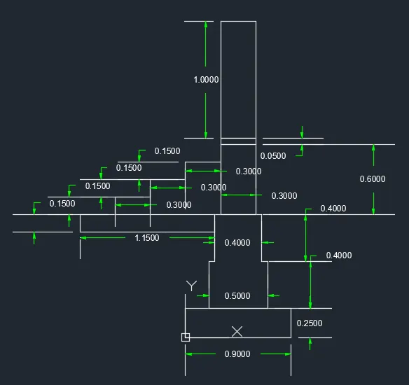
- Cross-Section of Load Bearing wall over spread footing =
Procedure =
- Select the rectangle tool by entering RECTANG in the command toolbar
- Specify the first point 0,0 in the command toolbar
- Then specify the rechangle dimesions as @0.90,0.25 in the command toolbar
- Then click the Enter
- Select the rectangle tool by entering RECTANG in the command toolbar
- Specify the first point 0.20,0.25 in the command toolbar
- Then specify the rechangle dimesions as @0.50,0.40 in the command toolbar
- Then click the Enter
- Select the rectangle tool by entering RECTANG in the command toolbar
- Specify the first point 0.30,1.05 in the command toolbar
- Then specify the rechangle dimesions as @0.30,0.60 in the command toolbar
- Then click the Enter
- Select the rectangle tool by entering RECTANG in the command toolbar
- Specify the first point 0.30,1.65 in the command toolbar
- Then specify the rechangle dimesions as @0.30,0.05 in the command toolbar
- Then click the Enter
- Select the rectangle tool by entering RECTANG in the command toolbar
- Specify the first point 0.30,1.70 in the command toolbar
- Then specify the rechangle dimesions as @0.30,1.00 in the command toolbar
- Then click the Enter
- Select the rectangle tool by entering RECTANG in the command toolbar
- Specify the first point 0.25,1.05 in the command toolbar
- Then specify the rechangle dimesions as @-1.15,-0.15 in the command toolbar
- Then click the Enter
- Select the line tool by entering the LINE in the coomand toolbar
- Specify the first point as -0.60,1.05 in the command toolbar
- Specify the co-ordinate of next point as @0,0.15 in the command toolbar
- Specify the co-ordinate of next point as @0.30,0 in the command toolbar
- Specify the co-ordinate of next point as @0,0.15 in the command toolbar
- Specify the co-ordinate of next point as @0.30,0 in the command toolbar
- Specify the co-ordinate of next point as @0,0.15 in the command toolbar
- Specify the co-ordinate of next point as @0.30,0 in the command toolbar
- Press ESC to cancel the line command
- Select the TRIM option and and trim the line between second and third rectangle
- Press ESC to cancel the TRIM command
- After that specify the Dimensions of Cross-section by Selecting DST and modify the dimension as per requirement
- Then click on Set current option select then close the tab
- And Give the specific dimention to the object
RESULT =
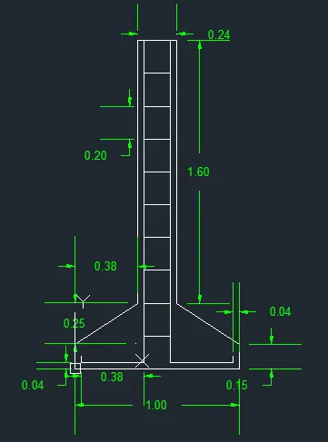
- Cross-Section of Isolated footing =
Procedure =
- Select the LINE tool by type in the command tool bar
- Specify the first point as 0,0 in the command tool bar
- Specify the co-ordinate of next point as @1.00,0 in the command tool bar
- Specify the co-ordinate of next point as @0,0.15 in the command tool bar
- Specify the co-ordinate of next point as @-0.38,0.25 in the command tool bar
- Specify the co-ordinate of next point as @0,1.60 in the command tool bar
- Specify the co-ordinate of next point as @-0.24,0 in the command tool bar
- Specify the co-ordinate of next point as @0,-1.60 in the command tool bar
- Specify the co-ordinate of next point as @-0.38,-0.25 in the command tool bar
- Then Click close on command tool bar
- Select the LINE tool by type in the command tool bar
- Specify the first point as 0.42,2.00 in the command tool bar
- Specify the co-ordinate of next point as @0,-1.96 in the command tool bar
- Specify the co-ordinate of next point as @-0.38,0 in the command tool bar
- Specify the co-ordinate of next point as @0,0.04 in the command tool bar
- Press ESC to cancel the line command
- Select the MIRROR tool by type in the command tool bar
- Select the object that we want to mirror that object and Press ENTER
- Then select first point and second point of mirror line and Select the NO in the Erase source object
- Select the OFFSET tool by type in the command tool bar
- Specify the 0.20 as offset distance by type in the command tool bar
- Select the top most line of the cross section of footing
- Then click on the side that you want offset the line
- Repeat the process 8 times and click on Esc to cancel offset command
- Select the Trim tool by type in the command tool bar and press enter
- Then trim the all 9 offset lines by seclecting Edge option and click on No Extend
- Press Esc to cancel the Trim Command
- After that specify the Dimensions of Cross-section by Selecting DST and modify the dimension as per requirement
- Then click on Set current option select then close the tab
- And Give the specific dimention to the object
RESULT =
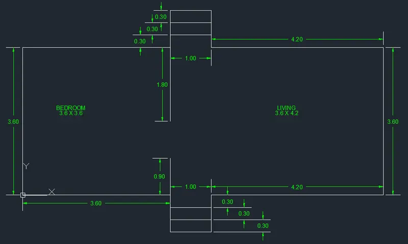
- Line Diagram of two Room Building =
Procedure =
- Select the LINE tool by type in the command tool bar
- Specify the first point as 0,0 in the command tool bar
- Specify the next point as 3.60 , pointing cursor in the Positive x - direction
- Specify the next point as 0.90 , pointing cursor in the Negative y - direction
- Specify the next point as 1.00 , pointing cursorin the Positive x - direction
- Specify the next point as 0.90 , pointing cursor in the Positive y - direction
- Specify the next point as 4.20 , pointing cursor in the Positive x- direction
- Specify the next point as 3.60 , pointing cursor in the Positive y - direction
- Specify the next point as 4.20 , pointing cursor in the Negative x- direction
- pecify the next point as 0.90 , pointing cursor in the Positive y - direction
- Specify the next point as 1.00 , pointing cursor in the Negative x - direction
- Specify the next point as 0.90 , pointing cursor in the Negative y - direction
- Specify the next point as 3.60 , pointing cursor in the Negative y - direction
- Press Close on the command line
- Select the offset tool by type the OFFSET command in the tool bar
- Enter 0.30 as offset distance in the command tool bar
- select the line 1.00 that we have to offset
- Specify the point on the side to offset
- Repeat the process for two times for both the stairs that given in the Line diagram of two room building
- Press Esc to cancel the OFFSET command
- Select the LINE tool by type the LINE command in the tool bar
- Now by selecting line tool we have draw the partition wall
- Specify the next point as 1.80, pointing cursor in the Negative y - direction
- Press Esc to cancel the line command
- Select the LINE tool by type the LINE command in the tool bar
- Specify the next point as 0.90 , pointing cursor in the Positive y - direction
- Press Esc to cancel the line command
- After that specify the Dimensions of Cross-section by Selecting DST and modify the dimension as per requirement
- Then click on Set current option select then close the tab
- And Give the specific dimention to the object
RESULT =
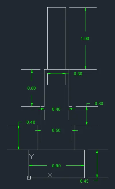
- Cross section of Load Bearing wall showing foundation details=
Procedure =
- Select the rectangle tool by entering RECTANG in the command toolbar
- Specify the first point 0,0 in the command toolbar
- Then specify the rechangle dimesions as @0.90,0.45 in the command toolbar
- Then click the Enter
- Select the LINE tool by type the LINE command in the tool bar
- Keep the ortho mode ON
- Specify the first point as 0.15,0.45 in the command tool bar
- Specify the next point as 0.40 , pointing the cursor in the Positive y - direction
- Specify the next point as 0.05 , pointing cursor in the Positive x- direction
- Specify the next point as 0.30 , pointing cursor in the Positive y - direction
- Specify the next point as 0.05 , pointing cursor in the Positive x - direction
- Specify the next point as 0.60 , pointing cursor in the Positive y- direction
- Specify the next point as 0.30 , pointing cursor in the Positive x - direction
- Specify the next point as 0.60 , pointing cursor in the Negative y - direction
- specify the next point as 0.05 , pointing cursor in the Positive y - direction
- Specify the next point as 0.30 , pointing cursor in the Negative y - direction
- Specify the next point as 0.05 , pointing cursor in the Positive x - direction
- Specify the next point as 0.40 , pointing cursor in the Negative y - direction
- Press Esc to cancel the line command
- Select the LINE tool by type the LINE command in the tool bar
- Specify the first point as 0.30,1.75 in the command tool bar
- Specify the co-ordinate of next point as @0,1.00 in the command tool bar
- Specify the co-ordinate of next point as @0.30,0 in the command tool bar
- Specify the co-ordinate of next point as @0,-1.00 in the command tool bar
- Press Esc to cancel the line command
- After that specify the Dimensions of Cross-section by Selecting DST and modify the dimension as per requirement
- Then click on Set current option select then close the tab
- And Give the specific dimention to the object
RESULT =
- Isometric views of steps =
Procedure =
- Turn on the isometric Drafting
- Select the isoplane left
- Select the LINE tool by type the LINE command in the tool bar
- click on ortho mode on option
- Specify the first point as 0,0 in the command tool bar
- Specify the next point as 1.00 , pointing the cursor in the Right - direction
- Specify the next point as 0.15 , pointing cursor in the Upward - direction
- Specify the next point as 1.00 , pointing cursor in the left - direction
- Specify the next point as 0.15 , pointing cursor in the Downword - direction
- Click Close option on the command toolbar
- Select the isoplane right or press the F5 function key to change isometric view
- Select the LINE tool by type the LINE command in the tool bar
- click on ortho mode on option
- Specify the first point as top corner of the object
- Specify the next point as 0.30, pointing the cursor in the Right - direction
- Press Esc to cancel the line command
- Select the COPY tool by type the CO command in the tool bar
- Select the line of length 0.30
- Specify the basepoint as the left top corner
- Copy the line Press Esc to cancel the command
- Select the COPY tool by type the CO command in the tool bar
- Select the line of length 0.30
- Specify the basepoint as the top right corner in the step
- Copy it at a distance of 0.15 downward rom the basepoint
- Press Esc to cancel the line command
- Select the COPY tool by type the CO command in the tool bar
- Select the diagram created above the two steps
- Specify the basepoint as the bottom left corner of the step
- then copy the selected diagram to the top left corner and repeat the process for three times
- Press Esc to cancel the line command
- Select the COPY tool by type the CO command in the tool bar
- select the line of 1.00
- Specify the basepoint as the top corner in the step and copy the line to the top corner
- Select the LINE tool by type the LINE command in the tool bar
- Specify the first point as top left corner
- specify the next point as 0.15, pointing the cursor in the downward direction then join the two edges of the stair
- Press Esc to cancel the line command
- After that specify the Dimensions of Stairs by Selecting DST and modify the dimension as per requirement
- Then click on Set current option select then close the tab
- And Give the specific dimention to the object
RESULT =
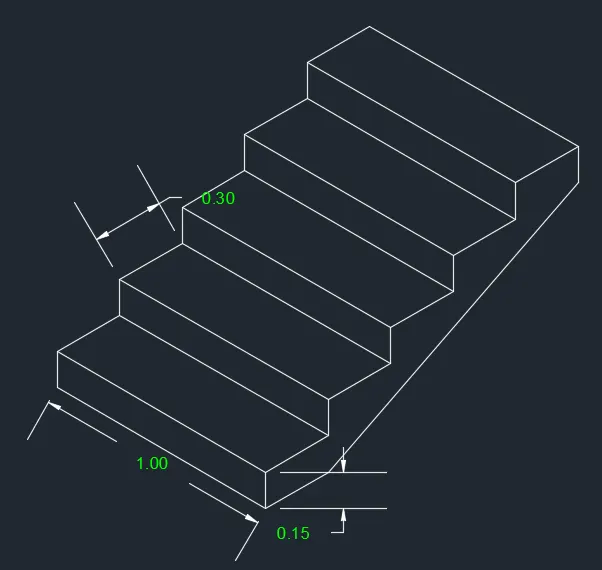
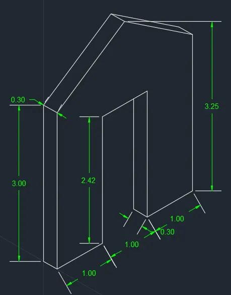
- Isometric views of gable wall =
Procedure =
- Turn on the isometric Drafting
- Select the isoplane left
- Select the LINE tool by type the LINE command in the tool bar
- click on ortho mode on option
- Specify the first point as 0,0 in the command tool bar
- Specify the next point as 3.00 , pointing the cursor in the Upward - direction
- Specify the next point as 0.30, pointing cursor in the left - direction
- Specify the next point as 3.00 , pointing cursor in the Downword - direction
- Click Close option on the command toolbar
- Select the isoplane right or press the F5 function key to change isometric view
- Select the LINE tool by type the LINE command in the tool bar
- click on ortho mode on option
- Specify the first point as top right corner of the object
- Specify the next point as 3.00, pointing the cursor in the Right - direction
- Specify the next point as 3.00, pointing the cursor in the Downword - direction
- Specify the next point as 1.00, pointing the cursor in the Left - direction
- Specify the next point as 2.42, pointing the cursor in the Upword - direction
- Specify the next point as 1.00, pointing the cursor in the Left - direction
- Specify the next point as 2.42, pointing the cursor in the Downword - direction
- Specify the next point as 1.00, pointing the cursor in the Left - direction
- Press Esc to cancel the line command
- elect the isoplane left
- Select the LINE tool by type the LINE command in the tool bar
- click on ortho mode on option
- Specify the first point inthe corner of the door opening
- Specify the next point as 0.30 , pointing the cursor in the left - direction
- Specify the next point as 2.12, pointing cursor in the Upword - direction
- Press Esc to cancel the line command
- Select the isoplane right or press the F5 function key to change isometric view
- Select the LINE tool by type the LINE command in the tool bar
- click on ortho mode on option
- Specify the first point at mid point of top line
- Specify the next point as 1.00, pointing the cursor in the Upword- direction
- Erase the unwanted lines
- Press Esc to cancel the line command
- Select the COPY tool by type the CO command in the tool bar
- select the top left corner line of 0.30 and select it
- Copy the lines in the top left,middle and right of the object
- Press Esc to cancel the line command
- After that specify the Dimensions of gable wall by Selecting DST and modify the dimension as per requirement
- Then click on Set current option select then close the tab
- And Give the specific dimention to the object
RESULT =