Creating a Residence Layout, Seating plan, Toilet and Utility room plan using AutoCad
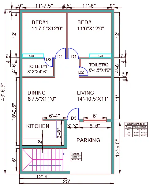
1. Residence Plan:
AIM :- Sketch the layout of a residence as shown in the Figure Consider all dimensions as reference to sketch the unit plan.
Procedure :-
- Type UNITS in the command tool bar
- Select the Enginnering Unit of measurement and select the precision as 0'-0.0"
- Select Inches in the insertion scale
- Click on the Layers properties and create the ne layers for External wall, Internal wall, Doors, Kitchen Slab, Window, Cupboard, Dimenstion & text and also specify the each layers has different colors
- Select the External wall layer as default layer
- Select the XLINE means construction line and draw the two lines intersecting with each other
- Press Esc to cancel the XLINE command
- Type TR coommand in the command tool bar
- Select the lines that should be trim and trim the lines
- press Esc to cancel the XLINE command
- Select the offset tool by entering OFFSET command in the command tab
- Type 9" as offset distance in the command tool bar and select the direction that you should set an offset
- Give the offset for both the horizontal and vertical lines
- press Esc to cancel the Offset command
- Select the offset tool by entering OFFSET command in the command tol bar
- for verical line Type 25' as offset distance in the command tool bar and also offset that line by distace of 9"
- for horizontal line Type 43'6.5" as offset distance in the command tool bar and also offset that line by distace of 9"
- press Esc to cancel the Offset command
- Type TR coommand in the command tool bar
- Select the lines that should be trim and trim the lines
- press Esc to cancel the trim command
- Select the offset tool by entering OFFSET command in the command tab
- for left bottom horizontal inner line is offset at distance of 6' and also offset that line by distace of 9"
- for left bottom horizontal outer line is offset at distance of 13'9.5" and also offset that line by distace of 9"
- for left outer vertical line is offset at distance of 12'6" and also offset that line by distace of 9"
- then extend, trim the lines as per the requirements in the plan
- After that Select the Internal wall layer as default layer
- Select the offset tool by entering OFFSET command in the command tab
- Type 4.5" distance in the command tool bar for all the internal wall
- Then draw the all internal wall as per distances given in the residential plan
- then extend, trim the lines as per the requirements in the plan
- After that Select the Stairs layer as default layer
- Select the line tool by entering LINE command in the command tab
- sketch the line of length 6' at adistance of 2'9" from the left corner of plan
- press Esc to cancel the line command
- Select the offset tool by entering OFFSET command in the command tab
- Type 1' distance in the command tool bar for the stairs and repeat this 1' distance for 8 times
- press Esc to cancel the offset command
- Select the line tool by entering LINE command in the command tab
- Divide the 6' line in to two parts by draw line in in the middle point
- And draw the direction of stairs from left side stairs to right side stairs
- press Esc to cancel the line command
- Type TR coommand in the command tool bar
- Select the lines that should be trim and trim the lines
- press Esc to cancel the trim command
- After that Select the DOORS layer as default layer
- Select the line tool by entering LINE command in the command tab
- Specify the first point in the plan as any point in the plan
- Specify the next point at distance of 3" in downward direction press enter with respect to Specify the next point at distance of 3" in positive horizontal direction
- Specify the next point at distance of 1.5" in verical direction
- Specify the next point at distance of 1.5" in negative horizontal direction
- then click on Close command in the command tool bar
- Select the MIRROR tool by entering MIRROR command in the command tab
- Select the object and mirror that object
- move the object in the doors and place it at a corner of the doors
- Select the Mline tool by entering MLINE command in the command tab
- Select the scale option in the command tool bar
- type 3" in the command tool bar and press Enter
- Select the point of move object and type 2'9" in the command tool bar
- press Esc to cancel the trim command
- select the Arc tool and choose 3 Point option then select the 3 point and draw the arc
- press Esc to cancel the Arc command
- Draw the all doors by this method as per distance given in the residential plan
- After that Select the kitchen layer as default layer
- Select the offset tool by entering OFFSET command in the command tab
- Specify the offset distance as 2' and give the the offset for both horizontal and vertical line of inner line of kitchen
- press Esc to cancel the offset command
- Type TR coommand in the command tool bar
- Select the lines that should be trim and trim the lines
- press Esc to cancel the trim command
- After that Select the Window layer as default layer
- Select the line tool by entering LINE command in the command tab
- draw the 9" at the inner edge of bottom of living room
- press Esc to cancel the line command
- Select the offset tool by entering OFFSET command in the command tab
- Select the offset distance a 1'3"
- select the vertical line of 9" length
- Specify the point on side to offset
- After that again offset the new line to a distance of 6'
- select the vertical line of 9" length
- press Esc to cancel the offset command
- After that Select the Cupboard layer as default layer
- Select the Rectangle tool by entering Rectang command in the command tab
- Select the first point as the left corner of the BED #1 and move the cursor at the end of the line
- Select the offset tool by entering OFFSET command in the command tool bar
- Secify the offset distance as 1"
- Select the rectangle and click inside the rectangle
- press Esc to cancel the offset command
- Select the Copy tool by entering COPY command in the command tool bar
- after that copy to the right corner of BED #2
- press Esc to cancel the copy command
- By Type DST command in the command tool bar open the modify options
- Change the Arrow size to 1'
- Change the Text Height to 1'
- Click OK. Then click on set current and close the window
- Type Mtext command in the command tool bar
- Specify the Text height as 1' click Enter and press Esc
- After that Select the Hatching layer as default layer
- Sect the area that should be hatch and press enter
- Finally save the drawing
RESULT :-
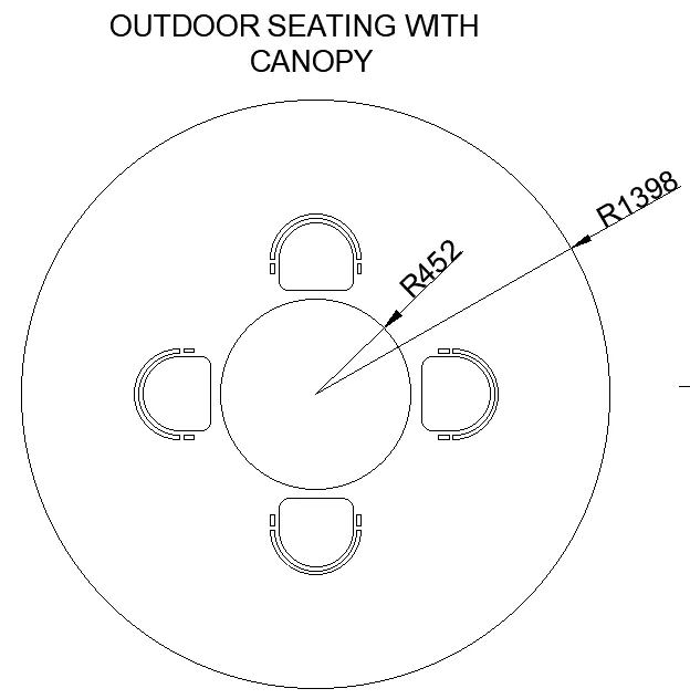
2. Outdoor Seating With Canopy:
AIM :- Sketch the seating plan for an outdoor canopy. Assume the dimensions for the seating. Also, consider the dimensions in mm.
Procedure :-
- Type UNITS in the command tool bar
- Select the Decimal Unit of measurement and select the precision as 0
- Select Millimeters in the insertion scale
- Select the Circle tool by entering CIRCLE command in the command tool bar
- select the centre, radius options from list
- Specify the centre point of circle as 0,0 in the command tool bar
- Specify the radius of circle as 452
- Again select the Circle tool by entering CIRCLE command in the command tool bar
- Select the centre, radius options from list
- Specify the centre point of circle as 0,0 in the command tool bar
- Specify the radius of circle as 1398
- Press Esc to cancel the circle tool
- Select the line tool by entering LINE command in the command tool bar
- Divide the circle into four parts using line tool
- Press Esc to cancel the line tool
- To draw the chair Select the Rectangle tool by entering RECTANG command in the command tool bar
- Specify the first point of Rectangle
- Select the dimensions options in the command line
- Select the Rectangle tool by entering RECTANG command in the command tool bar
- Select the length as 350 and width as 150
- Select the Fillet tool by entering FILLET command in the command tool bar
- select Radius as 50 Then select the lines to fillet
- Select the Arc tool by entering ARC command in the command tool bar
- Select the START, END, ANGLE option from the list
- BY specifying the start and end specify the angle of 90
- Select the offset tool and offset distance as 20 and again 20
- Press Esc to cancel the Offset tool
- To draw the chair of arms, Select the Rectangle tool by entering RECTANG command in the command tool bar
- Select the length as 20 and width as 50
- Select the chair move to it desired locations
- Use the Array tool in and select the polar array
- Select the chair and copy to 3 times specify the base point as the centre of circle
- Select the items in comman tool bar and specify the nuber as 4
- By Type DST command in the command tool bar open the modify options
- Change the Arrow size to 100
- Change the Text Height to 100
- Click OK. Then click on set current and close the window
- Type Mtext command in the command tool bar
- Specify the Text height as 100 click Enter and press Esc
- Finally save the drawing
RESULT :-
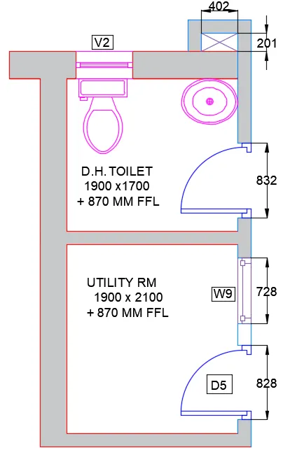
3. Sketch of Toilers & Utility Rooms:
AIM :- Sketch the part plan for the toilers and utilities room. Consider the outer wall thickness as 300mm and inner wall thickness as 150mm. Also, assume the missing dimension, Texts, dimensions, and hatches are only for references.
Procedure :-
- Type UNITS in the command tool bar
- Select the Decimal Unit of measurement and select the precision as 0
- Select Millimeters in the insertion scale
- Click on the Layers properties and create the ne layers for External wall, Internal wall, Doors, ventilator, Window, Duct, Dimenstion & text, fixtures and also specify the each layers has different colors
- Select the External wall layer as default layer
- Select the XLINE means construction line and draw the two lines intersecting with each other
- Press Esc to cancel the XLINE command
- Select the offset tool by entering OFFSET command in the command tol bar
- Select the offset distance as 300 mm in the command tool bar
- Select the Internal wall layer as default layer
- select the line of horizontal and vertical lines
- Specify the next offset as 1700 from the left inner vertical line
- Specify the next offset as 1900 from the upper inner horizontal line
- Again Specify the next offset as 150 from the previous offse line
- Again Specify the next offset as 2100 from the previous offset line
- Again Specify the next offset as 150 from the previous offse line
- Press Esc to cancel the Offset command
- Select the Duct layer as default layer
- Specify the next offset as 201 from the top most upper horizontal line
- Press Esc to cancel the Offset command
- Extend the right side corner line by selecting the line extend command
- Select offset tool and specify the offset distance as 402 in command tool bar
- Type TR coommand in the command tool bar
- Select the lines that should be trim and trim the lines
- Unwanted lines should be trim
- Select the DOOR layer as default layer
- Specify the next point at distance of 100 in downward direction press enter with respect to Specify the next point at distance of 100 in positive horizontal direction
- Specify the next point at distance of 50 in verical direction
- Specify the next point at distance of 50 in negative horizontal direction
- then click on Close command in the command tool bar
- Select the MIRROR tool by entering MIRROR command in the command tab
- Select the object and mirror that object
- move the object in the doors and place it at a corner of the doors
- Select the Mline tool by entering MLINE command in the command tab
- Select the scale option in the command tool bar
- type 50 in the command tool bar and press Enter
- Select the point of move object and type 728 in the command tool bar
- press Esc to cancel the trim command
- select the Arc tool and choose 3 Point option then select the 3 point and draw the arc
- press Esc to cancel the Arc command
- Draw the other doors by this method as per distance given in the residential plan
- Select the Window layer as default layer
- Select the line tool by entering LINE command in the command tab
- Position the window in the utility room
- press Esc to cancel the line command
- Select the offset tool by entering OFFSET command in the command tab
- Specify the offset distance as 728
- specify the point on side to offset
- press Esc to cancel the offset command
- Select the line tool by entering LINE command in the command tab
- draw the line joining the last two lines to form window
- press Esc to cancel the line command
- Select the Ventilator layer as default layer
- Select the line tool by entering LINE command in the command tab
- Position the window in the Toilet
- press Esc to cancel the line command
- Select the offset tool by entering OFFSET command in the command tab
- Specify the offset distance as 631
- specify the point on side to offset
- press Esc to cancel the offset command
- Select the line tool by entering LINE command in the command tab
- draw the line joining the last two lines to form window
- press Esc to cancel the line command
- Select the Fixtures layer as default layer
- From the palettes panel select the Toilet & wash basin blocks
- And place it in the D.H Toilet
- By Type DST command in the command tool bar open the modify options
- Change the Arrow size to 100
- Change the Text Height to 100
- Click OK. Then click on set current and close the window
- Type Mtext command in the command tool bar
- Specify the Text height as 100 click Enter and press Esc
- Finally save the drawing
RESULT :-