Drafting of various geometries using Chamfer, Fillet tool in AutoCad
Aim: To draw the given drawings using Autocad 2023
Introduction: Autocad is a commercial Computer Aided Design(CAD), It is marked and developed as Autodesk. It was first released on december 1982. Autocad derived from a program, which was beganed in 1977 and then released in 1979 called as Interact CAD, and also called in early documents od autocad as microCAD, Auto desk cofounder was Michael Riddle.
The first version of cad was released in december 1982 and was supported on CP/M-80 computers, By march 1986 Aotocad has became most uniquitous cad program worldwide. The file format of autocad was .dwg, and its interchange file format to DXF, have become a standard. Autocad was included support for .dwf, a format developed and promoted by Autodesk, for publishing CAD date. In year 2022 the Autocad 36th major version was released and the 12th consecutive year of Autocad foe Mac.
CAD is a technology which replaces manual drawing with automated process, if you are a drafter, desingner, architect or engineer you have been used 2D or 3D CAD programs i.e., Autocad or Autocad LT software. Autocad helps you in draft construction documentation, explore ideas for design, viaualise concepts through photorealistic renderings and gives how a design performs in real world.
Autocad mailnly used by industries, architects, engineers, city planners, project managers, graphic designers and other professionals.
1.
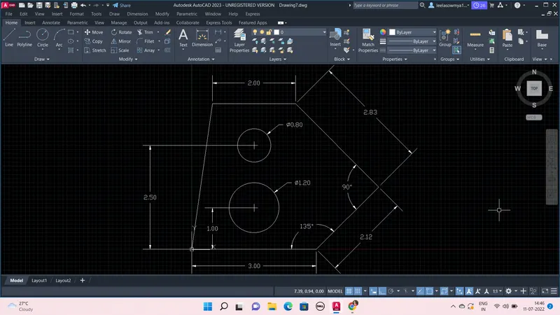
Steps:
- Open new file in Autocad 2023, Type UNITS, use decimal and take meters
- Then LIMITS, Limits of lower left corner give (0,0) and limits of upper right corner (10,10)
- Type DS (drafting settings) and go to snap and grid ON snap and grid, give snap X and Y spacing as 0.1, and Grid X and Y spacing as 0.1 and major lines are taken at every 5 minor lines.
- Take line command and first point is (0,0) and next points are (@3,0) (@2.12<45) (@2.83<135) (-2,0) and then close.
- Now take circle, center as (1.5,1) and dia 1.2 and again circle at (1.5,2.5) center and dia is 0.8
- Then using Dimension and mark the lines dimension and angle by taking Dimangular and by Dimdia to mark diameter of circle, To modify dimensions- Go to dimenstion in tool bar and then to dimension style.
2.
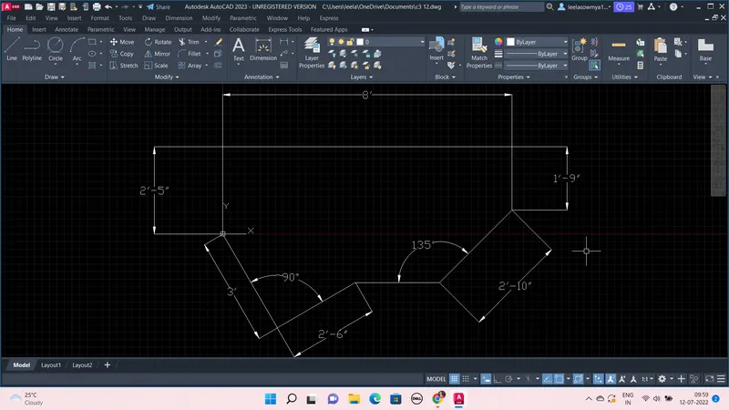
Steps:
- Open new file in Autocad 2023, Type UNITS, use Architectural and take inches
- Then LIMITS, Limits of lower left corner give (0,0) and limits of upper right corner (50,50)
- Type DS (drafting settings) and go to snap and grid ON snap and grid, give snap X and Y spacing as 0.1, and Grid X and Y spacing as 0.1 and major lines are taken at every 5 minor lines.
- Take line command and first point is (0,0) and next points are (@0,2'5") (@8',0) (@0,-1'9") (@2'10"<225)
- Then take Circle command and with center at (0,0) draw circle with radius of 3' and draw line from center (0,0) to (3',0) from that point to (@0,2'6"), Now join at (0,0) so a right angled triangle is formed
- Then draw circle at center (0,0) and with radius equal to Hypotenuse of the right angled triangle
- Now draw a reference horizontal line from line of length 2'10", then it intersects with bigger circle.
- Then from that point to draw tangent to inner circle which of 3' radius
- Then join that line to (0,0)
- Use Trim command and remove all unnecessary lines and circles
- Then using Dimension and mark the lines dimension and angle by taking Dimangular and by Dimdia to mark diameter of circle, To modify dimensions- Go to dimenstion in tool bar and then to dimension style.
3.
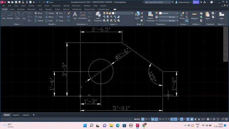
Steps:
- Open new file in Autocad 2023, Type UNITS, use Engineering and take inches
- Then LIMITS, Limits of lower left corner give (0,0) and limits of upper right corner (10,10)
- Type DS (drafting settings) and go to snap and grid ON snap and grid, give snap X and Y spacing as 0.1, and Grid X and Y spacing as 0.1 and major lines are taken at every 5 minor lines.
- Take line command and first point is (0,0) and next points are (@5'0.1") (@0,1'6") and exit from line command.
- Again take line, first point is (0,0) and next (@0,3'3") and then (@2'.6.5",0), Now join the line with previous line of length 1'6"
- Now take circle at centre (1'3",1'6") and dia= 1;6"
- Then using Dimension and mark the lines dimension and angle by taking Dimangular and by Dimdia to mark diameter of circle, To modify dimensions- Go to dimenstion in tool bar and then to dimension style.
4.
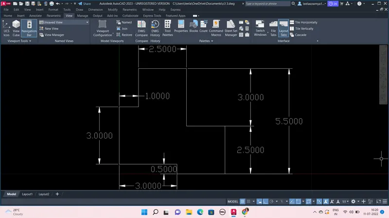
Steps:
- Open new file in Autocad 2023, Type UNITS, use decimal and take meters
- Then LIMITS, Limits of lower left corner give (0,0) and limits of upper right corner (10,10)
- Type DS (drafting settings) and go to snap and grid ON snap and grid, give snap X and Y spacing as 0.1, and Grid X and Y spacing as 0.1 and major lines are taken at every 5 minor lines.
- Take line command and first point is (0,0.5) and next points are (@3,0) (@0,-0.5) (@2.5,0) (@0,2.5) (@-2,0) (@0,3) (@-2.5,0) (@0,-2) (@-1,0) (@0,-3)
- Then using Dimension and mark the lines dimension ,To modify dimensions- Go to dimenstion in tool bar and then to dimension style.
5.
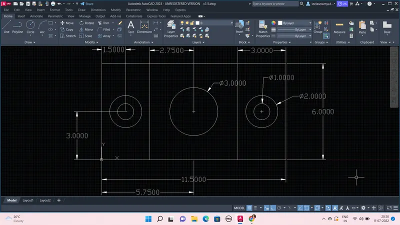
Steps:
- Open new file in Autocad 2023, Type UNITS, use decimal and take meters
- Then LIMITS, Limits of lower left corner give (0,0) and limits of upper right corner (10,10)
- Type DS (drafting settings) and go to snap and grid ON snap and grid, give snap X and Y spacing as 0.1, and Grid X and Y spacing as 0.1 and major lines are taken at every 5 minor lines.
- Take rectangular of first point (0,0) and opposite point as (11.5,6)
- Now take line command and first point as (3,0) and (@0,6) and again line first point as (8.5,0) and next (0,6)
- Now take circle at center (1.5,3) and dia= 1 and from centre draw another circle with dia 2
- Again circle, center as ( 5.75,3) and with dia 3
- Take circle at center (10,3) and dia= 1 and from centre draw another circle with dia 2
- Then using Dimension and mark the lines dimension and angle by taking Dimangular and by Dimdia to mark diameter of circle, To modify dimensions- Go to dimenstion in tool bar and then to dimension style.
6.
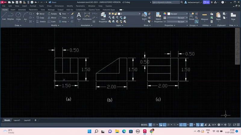
Steps:
- Open new file in Autocad 2023, Type UNITS, use decimal and take meters
- Then LIMITS, Limits of lower left corner give (0,0) and limits of upper right corner (10,10)
- Type DS (drafting settings) and go to snap and grid ON snap and grid, give snap X and Y spacing as 0.1, and Grid X and Y spacing as 0.1 and major lines are taken at every 5 minor lines.
(a)
- To draw this (a) figure, take Line from (0,0) then next points (@1.5,0) (@0,1.5)
- Now take offset and distance 0.5 and select the vertical line, offset leftside for 3times at 0.5distance then offset the horizontal line at 0.5 and 1 in upward
- Take trim, and remove the unnecessary lines
- Then using Dimension and mark the lines dimension ,To modify dimensions- Go to dimenstion in tool bar and then to dimension style.
(b)
- To draw this (b) figure, take Line from anywhere then next points (@2,0) (@0,1.5) (@-0.5,0) (@0,-1) (@-1.5,0) then close.
- Now off the Ortho and join the points using line to get required inclined line
- Then using Dimension and mark the lines dimension ,To modify dimensions- Go to dimenstion in tool bar and then to dimension style.
(c)
- To draw this (b) figure, take Line from anywhere then next points (@2,0) (@0,1.5)
- Now take offset and distance 0.5 and select the horizontal line, offset upward for 3times at 0.5 distance then offset the vertical line at 0.5 and 1 towards left
- Take trim, and remove the unnecessary lines
- Then using Dimension and mark the lines dimension ,To modify dimensions- Go to dimenstion in tool bar and then to dimension style.
7.
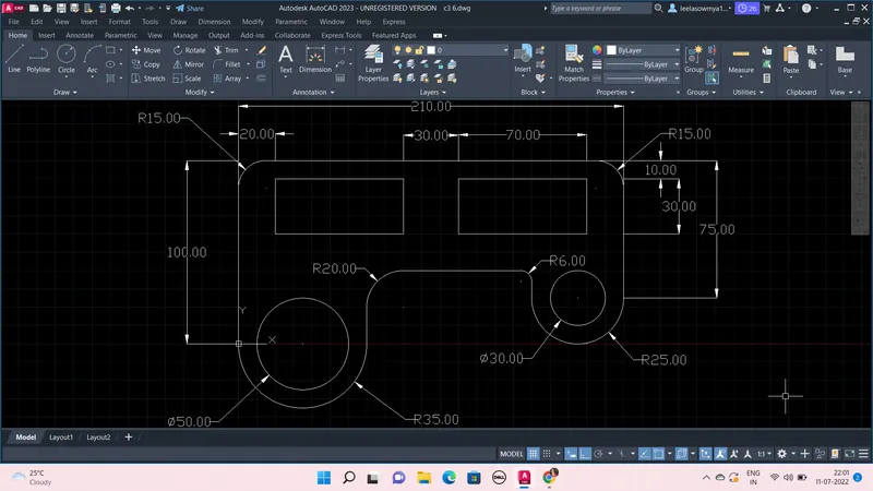
Steps:
- Open new file in Autocad 2023, Type UNITS, use decimal and take millimeters
- Then LIMITS, Limits of lower left corner give (0,0) and limits of upper right corner (420,297)
- Type DS (drafting settings) and go to snap and grid ON snap and grid, give snap X and Y spacing as 10, and Grid X and Y spacing as 10 and major lines are taken at every 5 minor lines.
- Take Line command and first point is (0,0) and next points are (@0,100) (@210,0) (@0,-75) (@50,0) (@0,15), exit from command
- Again Line from (0,0) to (@70,0) (@0,40) then join with previous line
- Now take circle, center at (35,0) radius 35 and with same center draw another circle with dia 50
- Take circle and center at 50mm horizontal line mid point and give radius 25, again with same center draw another circle of dia 30
- Use offset command and select 210mm horizontal line and offset at a distances of 10, 30 in inward direction.
- Now offset the vertical 75mm line at distances 20, 70, 30, 70 towards left
- Use Trim command and remove all unnecessary lines
- Now use Fillet and give radius as 15 and fillet the upper two corners
- Fillet the inner right corner with radius of 6 and inner left corner with radius 20
- Then using Dimension and mark the lines dimension and angle by taking Dimangular and by Dimdia to mark diameter of circle, To modify dimensions- Go to dimenstion in tool bar and then to dimension style.
8.
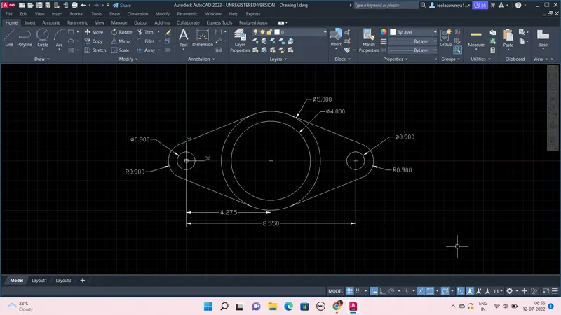
Steps:
- Open new file in Autocad 2023, Type UNITS, use decimal and take meters
- Then LIMITS, Limits of lower left corner give (0,0) and limits of upper right corner (10,10)
- Type DS (drafting settings) and go to snap and grid ON snap and grid, give snap X and Y spacing as 0.1, and Grid X and Y spacing as 0.1 and major lines are taken at every 5 minor lines.
- Take line command and first point is (0,0) and next point is (8.55,0)
- Take Circle command and center at (4.275,0) and dia is 4 and with same center draw another circle with dia 5units
- Now take Circle, center at (0,0) give dia as 0.9 and with same center draw another circle with radius 0.9
- Again take Circle, center at (8.55,0) give dia as 0.9 and with same center draw another circle with radius 0.9
- Now type DS and goto Object snap and on Tangent
- Take Line from circle of radius 0.9 draw a tangent to cirle of dia 5 and also draw tangent from bottom.
- Again tangent from another circle of rad 0.9 to dia 5 circle at top and bottom
- Use Trim command and remove all unnecessary lines
- Then using Dimension and mark the lines dimension and angle by taking Dimangular and by Dimdia to mark diameter of circle, To modify dimensions- Go to dimenstion in tool bar and then to dimension style.
9.
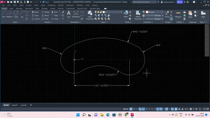
Steps:
- Open new file in Autocad 2023, Type UNITS, use Engineering and take inches
- Then LIMITS, Limits of lower left corner give (0,0) and limits of upper right corner (50,50)
- Type DS (drafting settings) and go to snap and grid ON snap and grid, give snap X and Y spacing as 0.1, and Grid X and Y spacing as 0.1 and major lines are taken at every 5 minor lines.
- Take line command and first point is (0,0) and next point is (32'6",0)
- Take Circle command and center as (0,0) radius is 8' and another circle at (32'6",0) with radius as 9'
- Now take Tan Tan Radius, and click on top side of two circles and give radius as 41'8"
- Again take Tan Tan Radius, click on bottom side of two circles and give radius as 20'10"
- Use Trim command and remove all unnecessary lines
- Then using Dimension and mark the lines dimension and angle by taking Dimangular and by Dimdia to mark diameter of circle, To modify dimensions- Go to dimenstion in tool bar and then to dimension style.
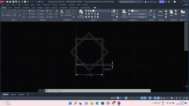
10.
Steps:
- Open new file in Autocad 2023, Type UNITS, use decimal and take meters
- Then LIMITS, Limits of lower left corner give (0,0) and limits of upper right corner (10,10)
- Type DS (drafting settings) and go to snap and grid ON snap and grid, give snap X and Y spacing as 0.1, and Grid X and Y spacing as 0.1 and major lines are taken at every 5 minor lines.
- Take Rectangle command and first point is (0,0) and opposite corner is (3,3)
- Now take offset and give distance as 0.15, select the square and offset outwards
- Then take copy command and select the two squares and copy and some distance
- Now using Rotate command Rotate the copied objects at 45 degrees
- Then again copy the rotate objects and keep on main objects, basepoint is selected as center point of square
- Use Trim command and remove all unnecessary lines
- Then using Dimension and mark the lines dimension,To modify dimensions- Go to dimenstion in tool bar and then to dimension style.
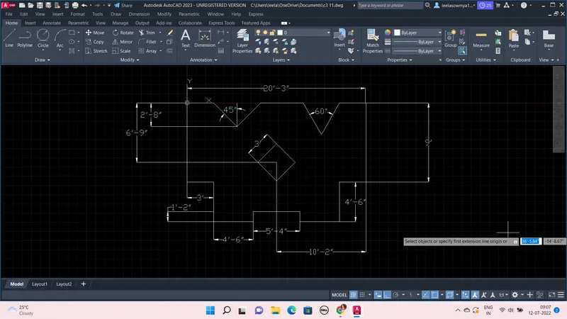
11.
Steps:
- Open new file in Autocad 2023, Type UNITS, use Engineering and take inches
- Then LIMITS, Limits of lower left corner give (0,0) and limits of upper right corner (50,50)
- Type DS (drafting settings) and go to snap and grid ON snap and grid, give snap X and Y spacing as 0.1, and Grid X and Y spacing as 0.1 and major lines are taken at every 5 minor lines.
- Take line command and first point is (0,0) and next points are (@0,-9') (@3',0) (@0,-4'6") (@4'6",0) (@0,1'2") (@5'4",0) (@0,-1'2") (@4'6",0) (@0,4'6") (@3',0) (@0,9') (@-3',0) and by calculating Length of inclined line is 4'1.75", so from previous point draw line to (@4'1.75"<240) next point is (@4'1.75"<120)
- Now again take Line first point is (0,0) and next (@3',0) (@3'9.3"<315) (@3'9.3"<45) and join to previous point.
- Take offset and select vertical line of 9' and offset to a distance of 10'2" and again take top horizontal line which jointed inclined line and offset it to a distance of 6'9"
- Now the offseted lines are again offset those lines at a distance of 1.5' on bothsides
- Use Trim command and remove all unnecessary lines and a Square of 3' is formed.
- Now select the square and Rotate it for 45 degrees
- Then using Dimension and mark the lines dimension,To modify dimensions- Go to dimenstion in tool bar and then to dimension style.