Creating a Residence Layout, Seating plan, Toilet and Utility room plan using AutoCad
- Residence Plan:
Sketch the layout of a residence as shown in the Figure 1. Consider all dimensions as reference to sketch the unit plan. Also the text in the layout are only for reference. Assume the missing dimensions. Also, refer the schedule for size of the doors.
SOLUTION- 1 :
AIM: To draw the sketch of layout of residence as shown in Figure 1 using various AutoCad tools like Hatch, trim, offset, rectangle, table, copy, layers etc. as required to complete the drawing in AutoCad.
PROCEDURE.
Set up the drawing in Imperial units and select Engineering.
Set up the limits of drawing as per the size of drawing and also extents of zoom for easy reference.
Select line command with centre (10,10) and draw outer lines of the building of 25’ width and 43’6.5” length on all four side.
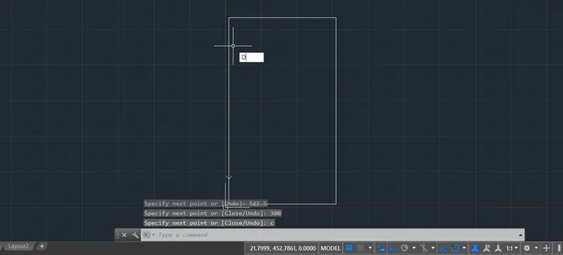
Offset the outer lines inside by 9” for the wall thickness
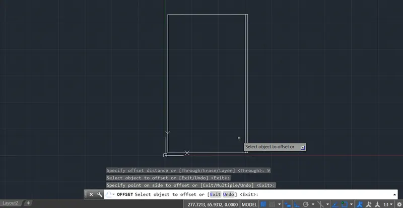
Draw the internal wall lines as per the room dimensions by offsetting the outer lines
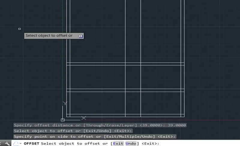
Trim the lines as per the openings of doors etc as per drawing
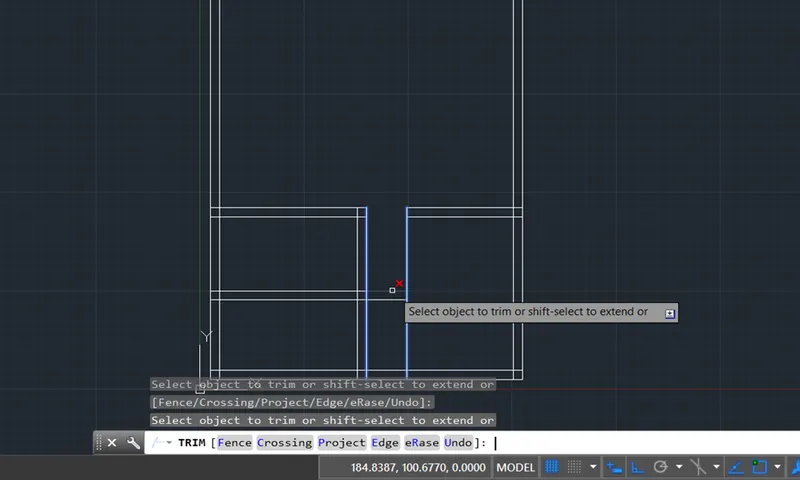
Copy the internal wall lines and displace by 4.5” for internal all thickness.
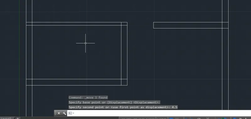
Offset the lines in kitchen by 2’ for the kitchen platform as per figure
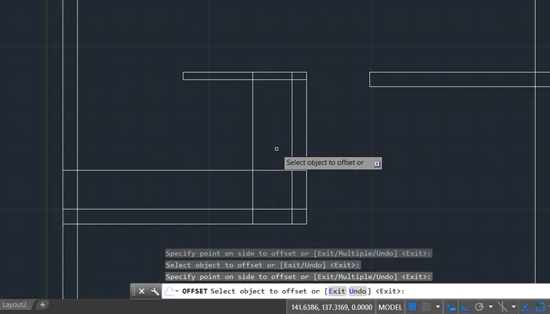
Trim the unwanted lines
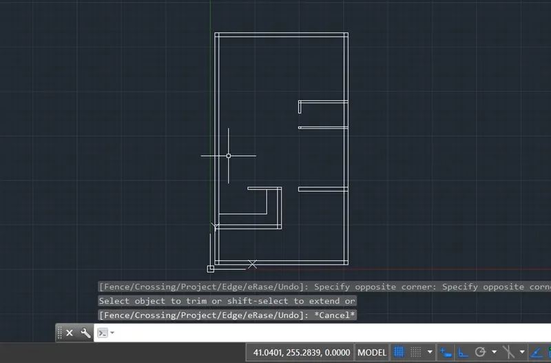
Draw the toilet wall lines as per the room dimensions, extend the lines as per required boundaries
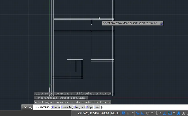
Copy the partition lines and paste for the second toilet after the passage distance as per figure
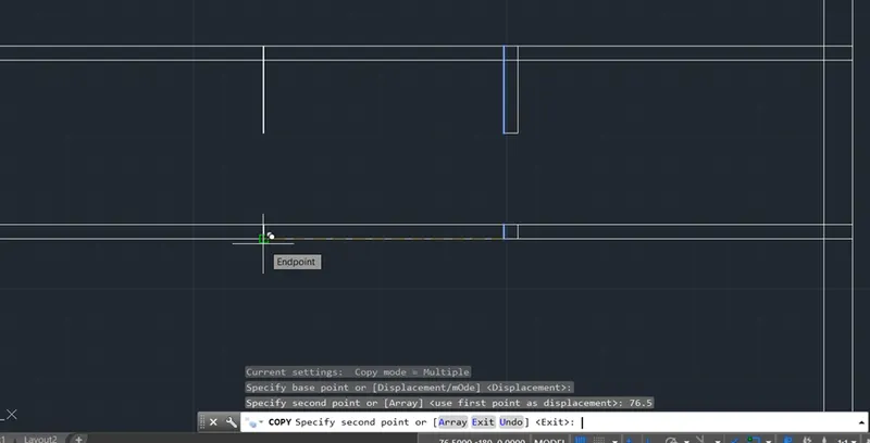
Trim the unwanted lines
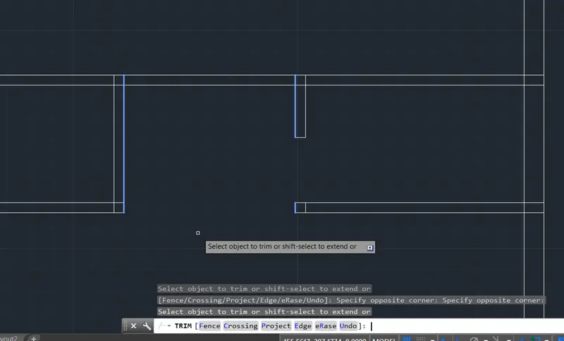
Draw the Partition wall by offsetting and trimming as per room dimensions
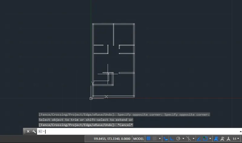
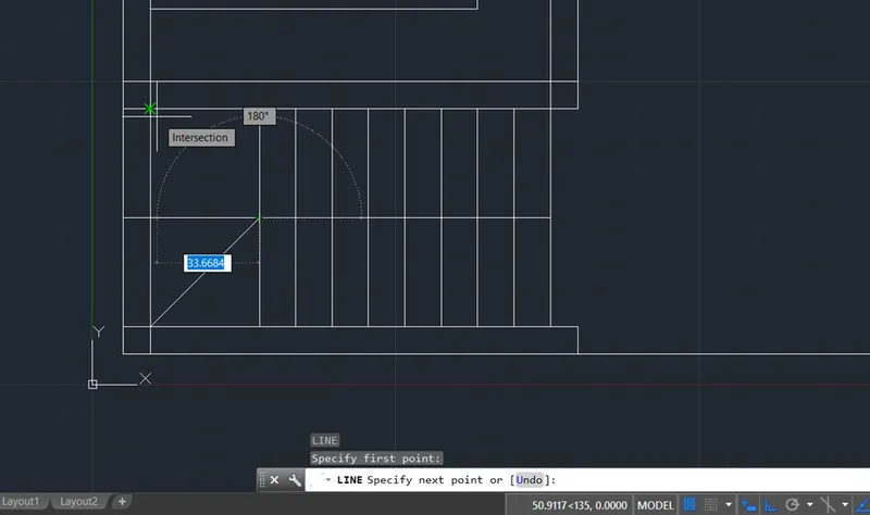
Draw the staircase steps using Array command for 9 steps and 12” tread.
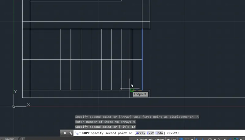
Draw the cross winders by line command as shown in the drawing for landings
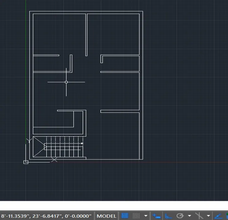
Change the upper steps of stairs to hidden lines as shown in figure by changing the line type and show the upward path of staircase by arrow and line
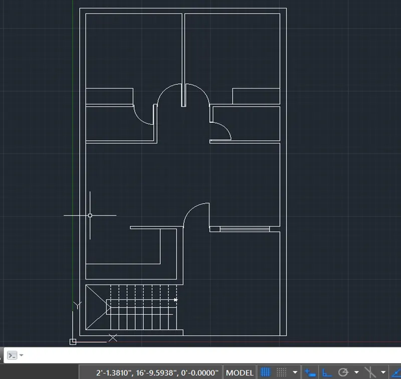
Draw the doors using the Arc command for the door openings and mark widows as per the dimensions in figure
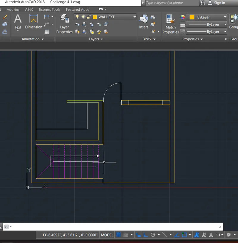
Assign the layer properties by creating new layers for wall, door, window, stair, text, kitchen platform, cupboard, etc. by separate colours and linewidths.
Select the lines and assign the layers accordingly to the drawing.
Insert the table of required rows and columns for door schedule as per figure.
Provide the dimensions as per figure using dimlinear command, enter the room name and sizes using multi line text command.
Adjust the dimension style as per the drawing requirement using DimStyle command.
Hatch the external and internal walls using hatch command and using solid hatch as per the given figure.
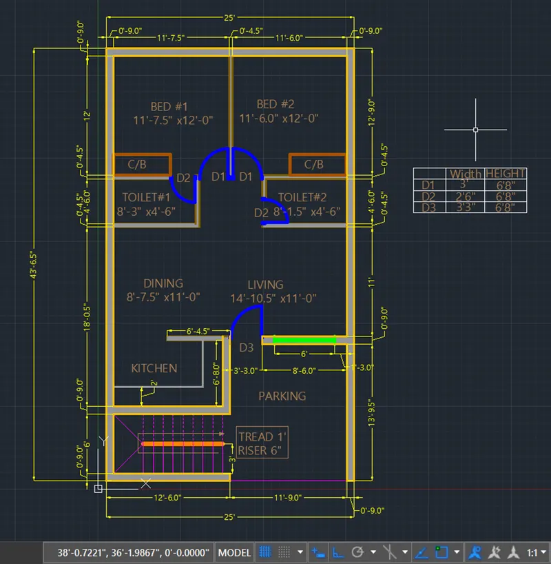
The final drawing is ready, the layer colours and thickness can be adjusted as required from the Layer properties.
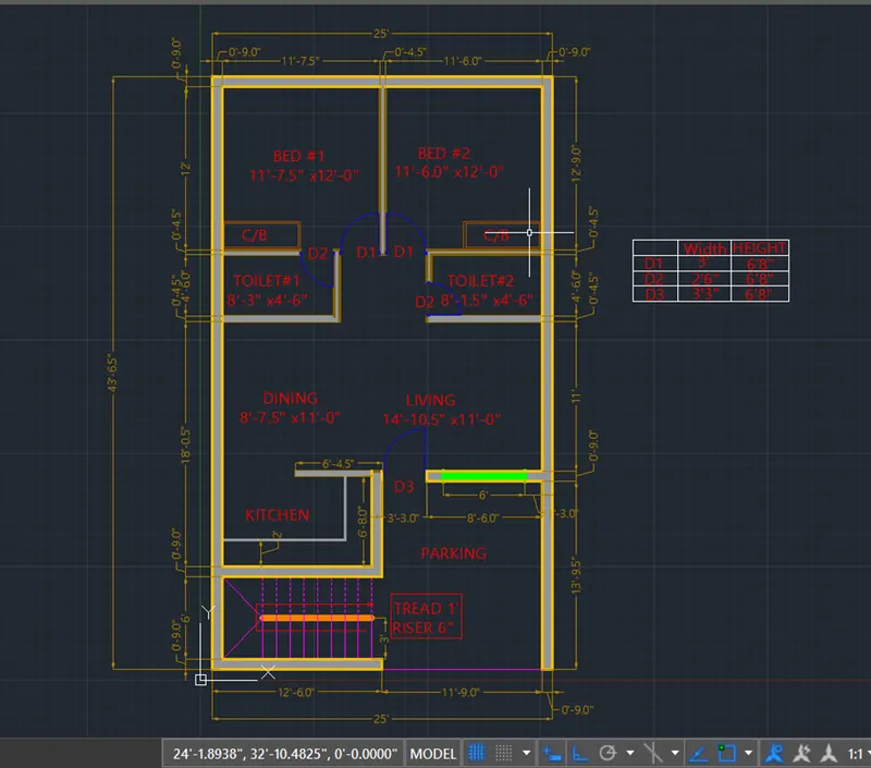
CONCLUSION : Thus we have drafted the given figure of the residential building layout using various tools in AutoCad. The procedure and stage wise screenshots of the drawing are attached for reference.
- Sketch the seating plan for an outdoor canopy. Assume the dimensions for the seating. Also, consider the dimensions in mm.
SOLUTION- 2 :
AIM: To draw the sketch of seating plan for an outdoor canopy as shown in Figure 2 using various AutoCad tools like circle, trim, offset, fillet, rectangle, array, copy, etc. as required to complete the drawing in AutoCad.
PROCEDURE.
Set up the drawing in Metric units and select Decimal for dimension style.
Set up the limits of drawing as per the size of drawing and also extents of zoom for easy reference.
Start with the Circle command with centre of (1500,1500) and draw the circle of radius 1368 units for the canopy line.
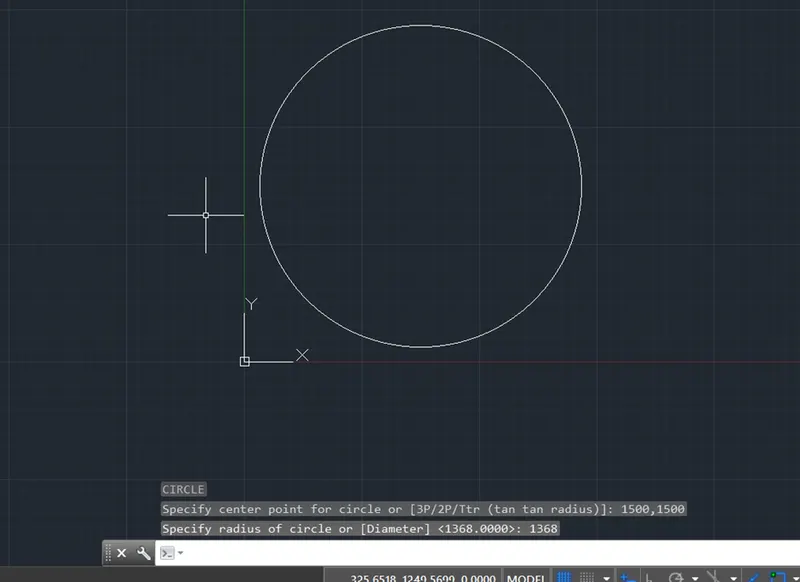
Then with same centre draw as Circle of radius 452 for the centre table as per figure.
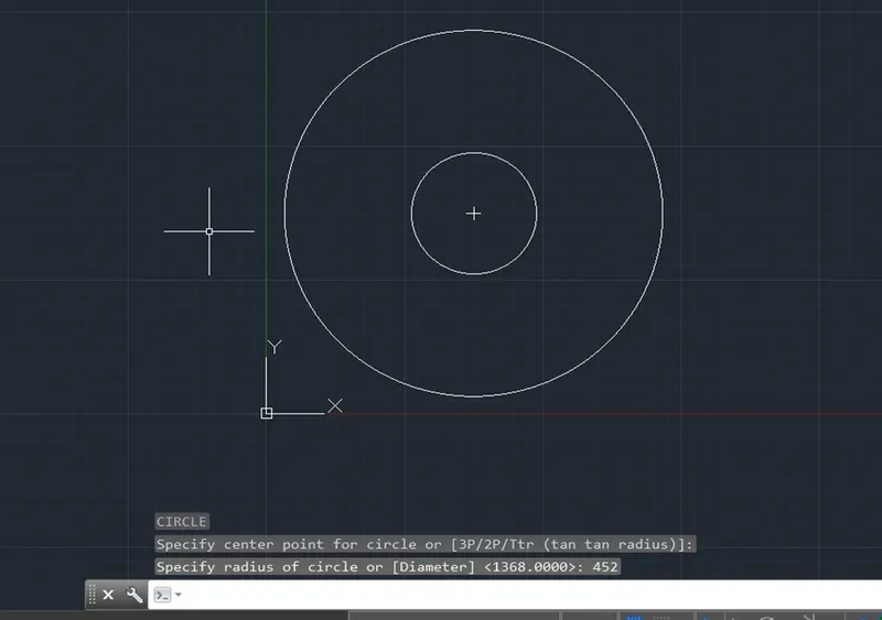
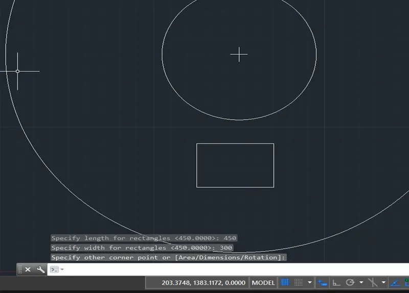
Assuming the width of chair to be 450mm draw as rectangle of 450 x300 by using rectangle command with dimensions.
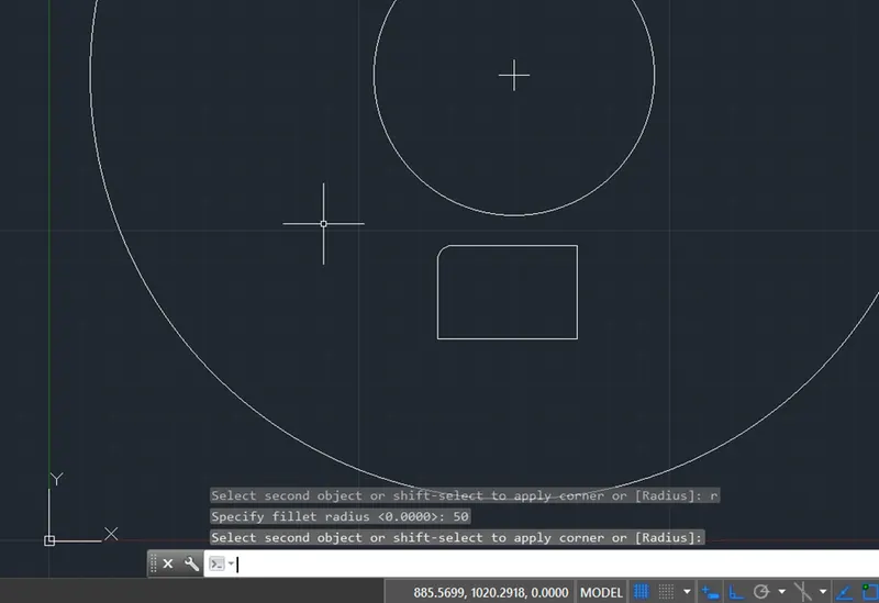
Fillet the front/upper two corners of the rectangle by 50mm radius for smooth corners of chair.
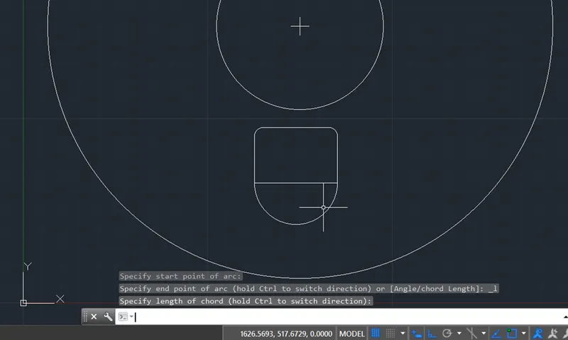
Draw an arc on the bottom side of rectangle to form circular back of the chair as shown in figure by using Arc command.
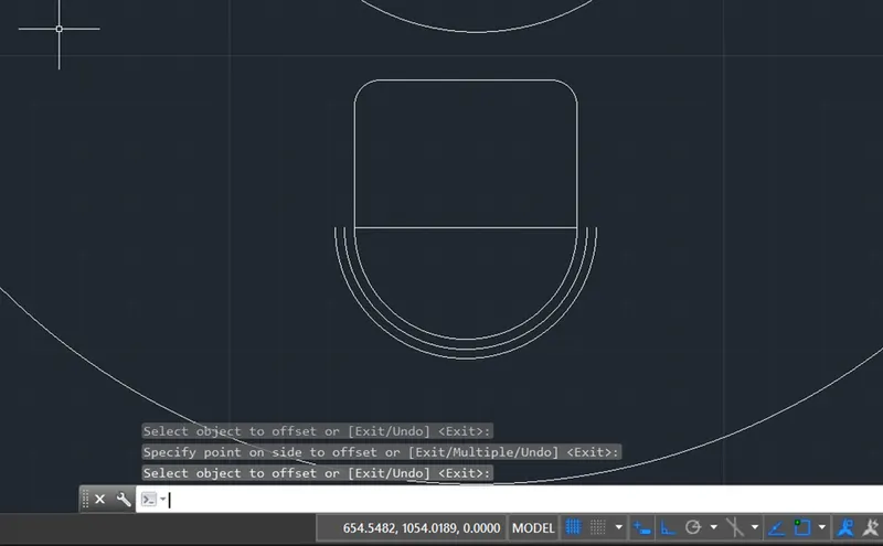
Offset the arc twice on outer side to show the thickness of the curved back rest.
Draw as rectangle of width of the backrest in continuation to form the hand rests on both sides of the chair.
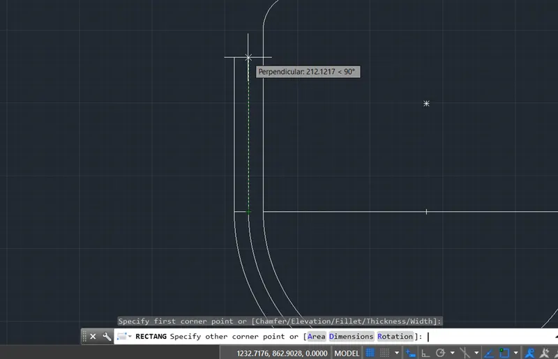
Shift the rectangle slightly away by 50mm to separate the hand rest from the backrest as shown in the figure.
Array the chair using 4 numbers using Arraypolar
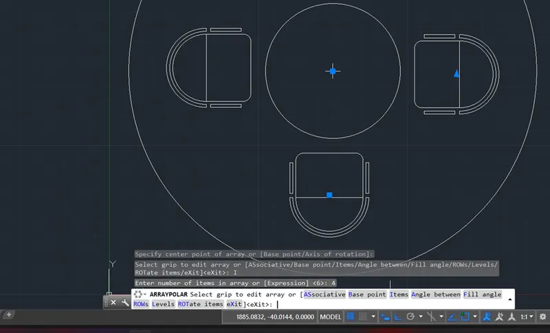
Delete the central line of rectangle seen in chair.
Provide the dimensions using Dimrad and Dimlinear.
The required drawing of the seating plan with outdoor canopy is completed in AutoCad.
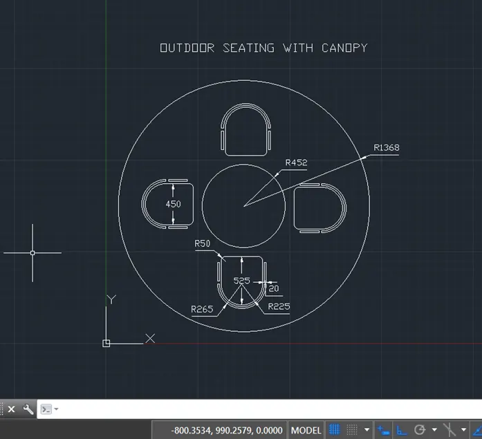
CONCLUSION,
The sketch of seating plan for an outdoor canopy as shown in Figure 2 is drafted in AutoCad using various tools. The procedure and the stage wise screenshots of AutoCad drawings are attached for reference.
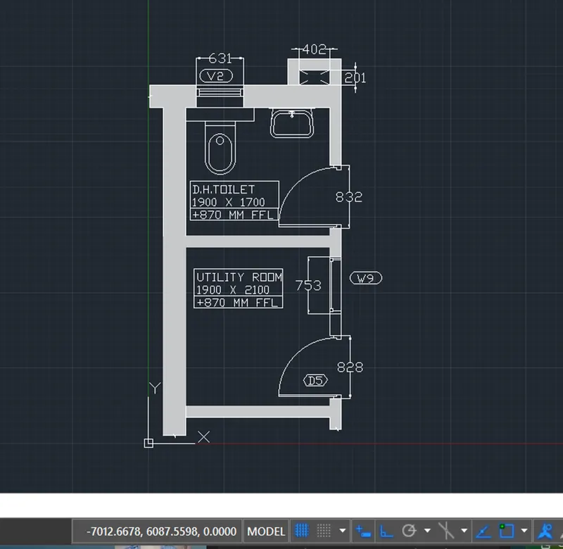
- Sketch the part plan for the toilers and utilities room. Consider the outer wall thickness as 300mm and inner wall thickness as 150mm. Also, assume the missing dimension, Texts, dimensions, and hatches are only for references. Also, symbols for toilets and w/c are also for references.
SOLUTION- 3 :
AIM: To draw the part plan for the toilets and utility room as shown in Figure 3 using various AutoCad tools like Hatch, trim, offset, rectangle,circle, copy, etc. as required to complete the drawing in AutoCad.
PROCEDURE.
Set up the drawing in Imperial units and select Engineering.
Set up the limits of drawing as per the size of drawing and also extents of zoom for easy reference.
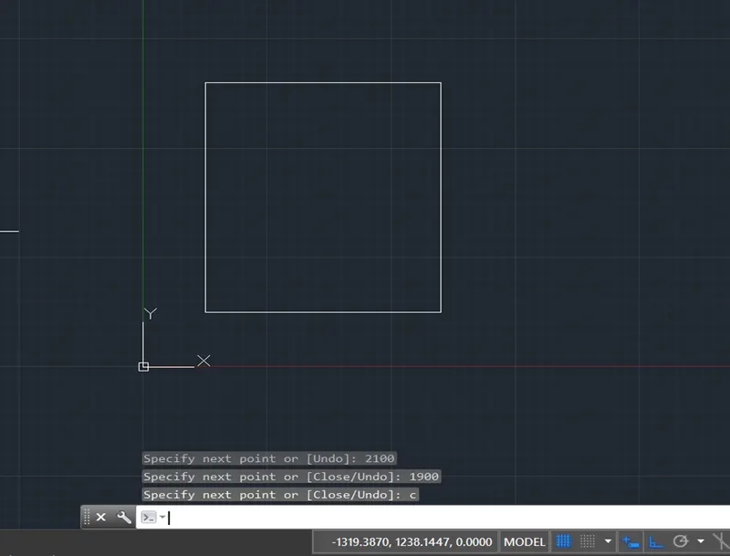
Start with line command with centre (500,500) and complete the rectangular figure of inner faces of Utility room of 1900 x 2100
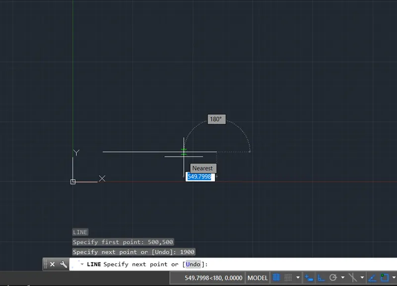
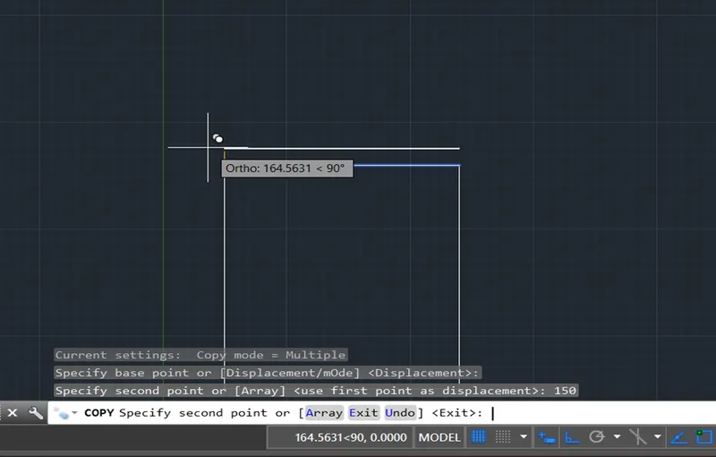
Copy the line and shift by 150mm for the internal wall between Utility and D.H. Toilet.
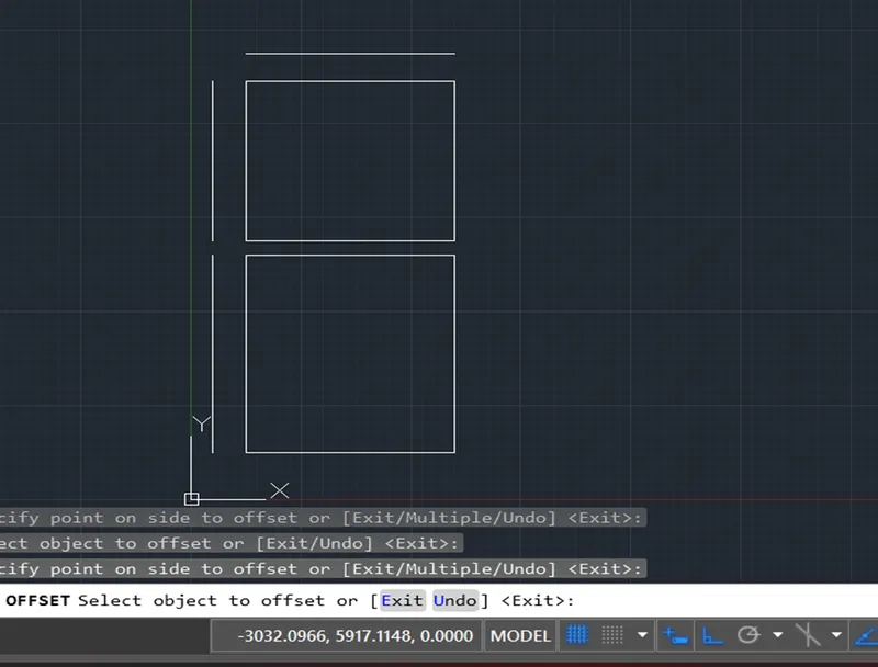
Similarly offset the left side lines for the outer wall by 300mm
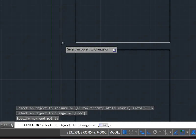
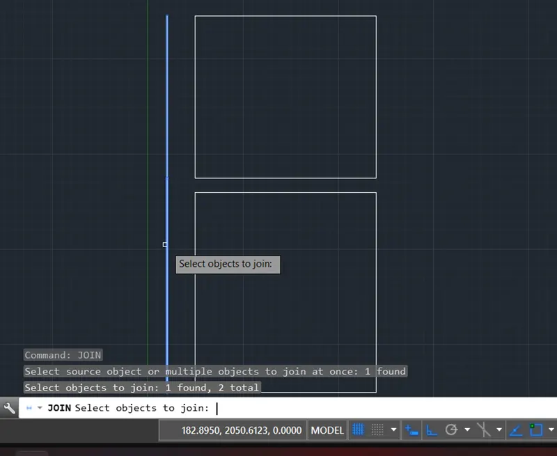
Extend the outer cut lines using lengthen command
Join the two lines meeting each other after lengthening to form outer continuous line
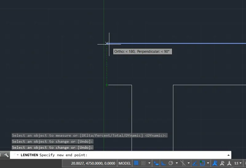
Extend the external partial line at top by using lengthen command equal to short extended line.
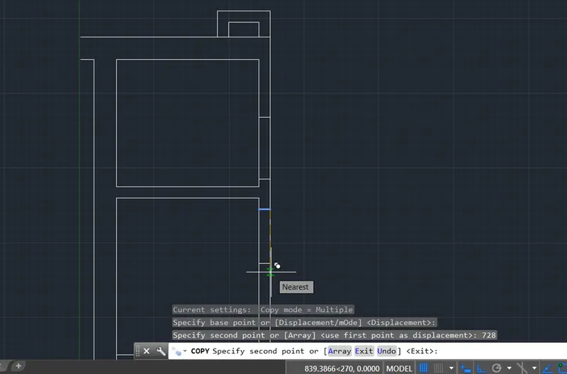
Provide the line for one side of the cut outs of windows and doors and copy and place it at the required door or window widths
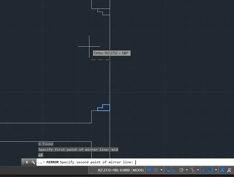
Draw a profile for the door frame on one edge and mirror it to other edge using Mirror command from the mid of opening.
Similarly draw the ventilator cut outs showing ventilator using line, rectangle, trim, offset commands
Draw the door swing and door leaf using rectangle command for leaf and Arc command for the swing.
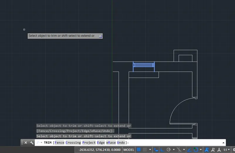
Draw the sanitary ware WC and Wash basin using the Rectangle, Arc, Fillet by radius, Circle, trim, extend, line etc commands, as per the given figure.
Hatch the internal and external walls as shown in the figure.
Provide the dimensions, door /window names, room levels and room names with sizes as shown in the figure.
The required drawing as per the figure is completed.
CONCLUSION,
The drawing of part plan for Toilet and Utility room as shown in Figure 3 is drafted in AutoCad using various tools. The procedure and the stage wise screenshots of AutoCad drawings are attached for reference.