Drafting of various geometries using Chamfer, Fillet tool in AutoCad
- AIM:- TO DRAFT CHAMFER AND FILLET TO VARIOUS GEOMETRIES USED IN AUTOCAD.
- INTRODUCTION:-
- This project is based upon the use of various designs that are used in designing the structures with the use of Chamfer (CHA) and Fillet (F) tools which are used to work with the edges and corners of the structures. These tools give various options to work with the design of the structure, which can make it more attractive, symmetric, and at equilibrium.
- Use of Line (L), Circle (C), Rectangle (REC) commands.
- Modifications in Dimension styles from the Dimension tab.
- Use of Dimension (DIM) command.
- Use of Trim (TR) and Extend (EX) commands.
- Use Layers to differentiate between elements of the geometries.
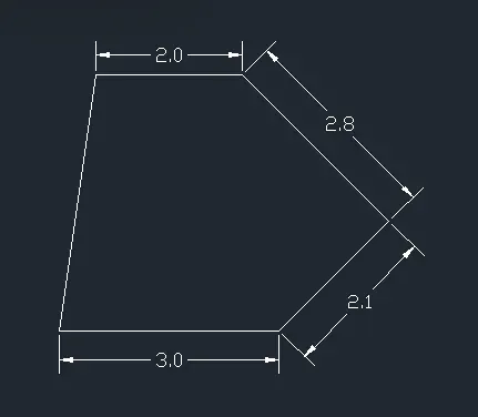
- FIGURE-1
- Steps:
- Type UN in the command box to change units to DECIMAL and precision to 0.0
- Type L in the command box to select line.
- Specify the first point of the line.
- Specify the next coordinates as "@3<0; @2.1<45; @2.8<135; @2<180 and then C" to close the figure.
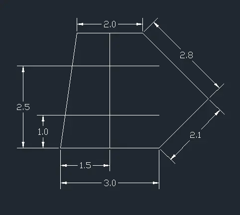
- Type O in the command box to select the Offset tool.
- Specify the distance as 1, then select the line and offset it.
- Again select the offset tool, and specify the distance as 2.5.
- Select the line and offset it.
- Draw a line from the mid-point of the bottom line intersecting both the offset lines.
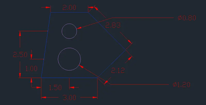
- Type C in the command box to select Circle.
- Specify the center of the circle at the intersection of the lines, then specify its radius as 0.40.
- Again select the circle, specify its center at the second intersection, then specify its radius as 0.60.
- RESULT:
- FIGURE-2
- Steps:
- Type L in the command line and specify the first point.
- Specify the next coordinates as "@29<90; @96<0; @21<270"
- Again select the line, specify the first point and the next coordinates as "@30<180; @36<90"
- Again select the line, specify the first point and the next coordinates as "@63.4<0; @34<45"
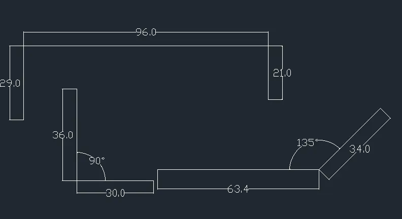
- Select the move tool and then select the objects and the ends of the line.
- Select the rotate tool, select the objects, and then rotate the objects till the inclined lines intersect.
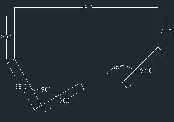
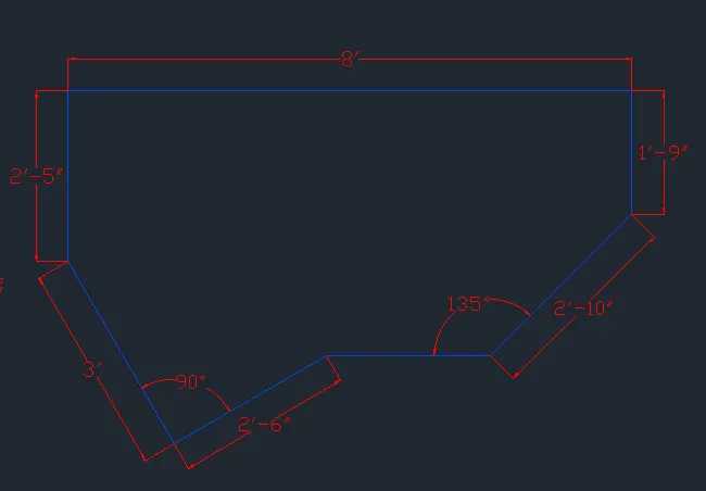
- Trim the excess lines.
- Specify the dimensions accordingly.
- FIGURE-3
- Steps:
- Change the units to Engineering.
- Type L in the command box to select the line tool.
- Specify the first point of the line.
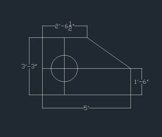
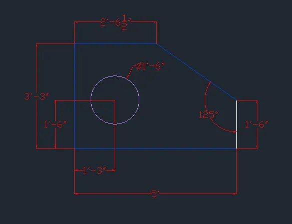
- Specify the next coordinates as "@1'6"<270; @5'<180; @3'3"<90; @2'6.5"<0 and then type C" to close the figure.
- Select the offset tool and specify its distance as 1'6", then select the bottom line and offset it.
- Again, select the offset tool and specify its distance as 1'3", then select the left vertical line and offset it.
- Type C in the command box to select the circle tool.
- Specify the center of the circle at the intersection and give the diameter as 1'6".
,
- Trim the excess lines.
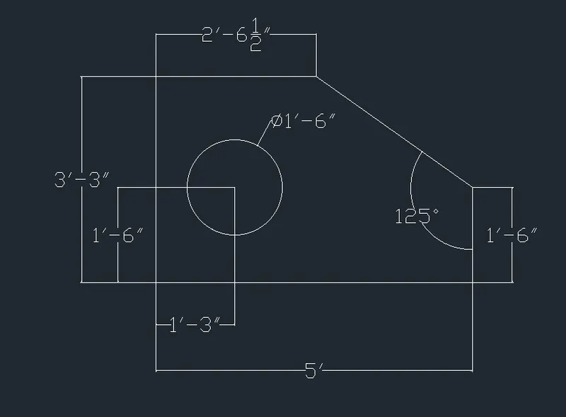
- Specify the dimensions.
- RESULT:
- FIGURE-4
- Steps:
- Type L in the command box to select the line command.
- Specify the first point of the line.
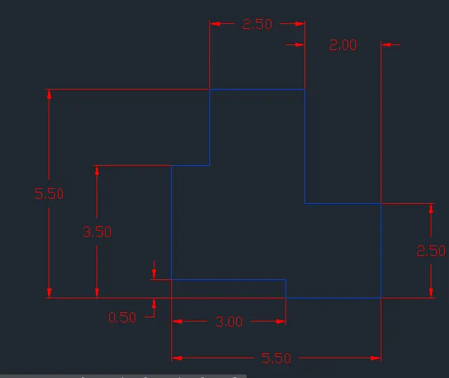
- Specify the coordinates as "@2<0; @2.5<270; @2.5<180; @0.5<90; @3<180; @3<90; @1<0; @2<90; @2.5<0 and then type C" to complete the figure.
- Specify the dimensions.
- RESULT:
- FIGURE-5
- Steps:
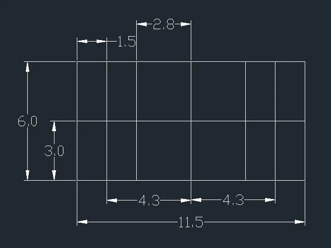
- Type REC in the command box to select the rectangle tool.
- Specify the first corner and select the dimensions option.
- Specify the length as 11.5 and width as 6 and press enter.

- Type O in the command box to select the offset tool.
- Specify the offset distance as 3 and draw the horizontal line.
- Again select the offset tool and specify the distances and draw the required vertical lines.
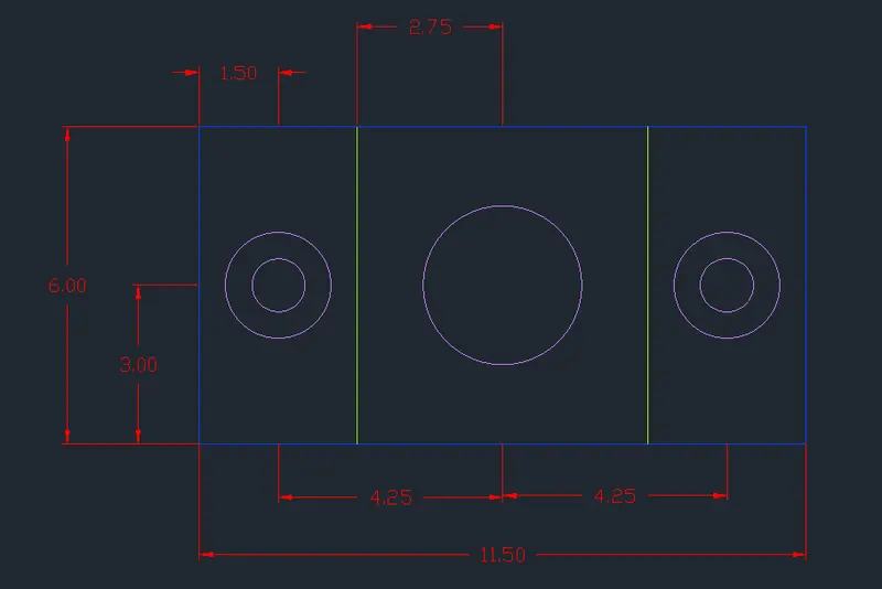
- Select the circle and specify the radius as 1.
- Again draw a circle concentric to the previous one with a radius of 0.5.
- Again draw a circle in the middle with a radius of 1.5.
- Trim the non-required lines.
- RESULT:
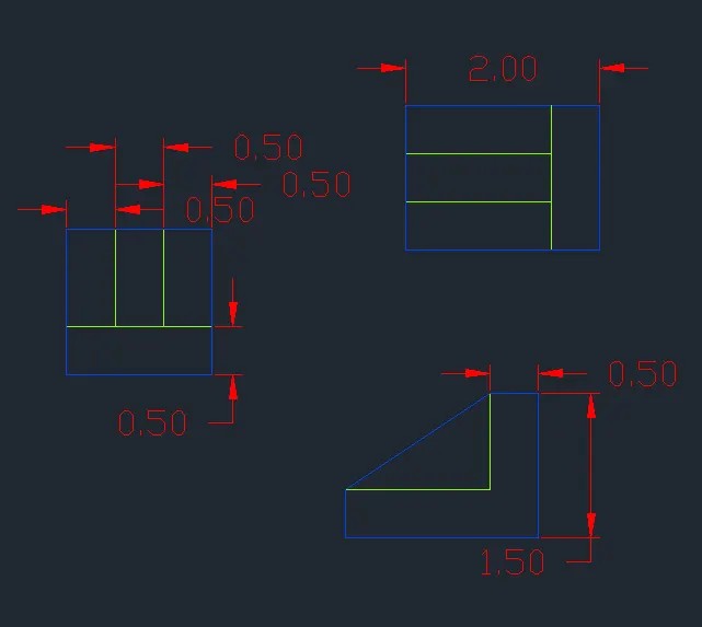
- FIGURE-6
- Steps:
- Type L in the command box to select the line tool and specify the first point.
- Specify the next coordinates as "@1.5<0; @1.5<270; @1.5<180 and then type C".
- Type O to select the offset tool and specify the distance as 0.5.
- Offset the required lines.
- For the 2nd picture, again type L in the command box to select a line and specify the first point.
- Specify the next coordinates as "@2<0; @1.5<270; @2<180; and then type C".
- Again select offset with a distance of 0.5 and draw the required lines.
- For the 3rd picture select the line, and specify the first point.
- Specify the coordinates as "@0.5<0; @1.5<270; @2<180; @0.5<90".
- Take offset of lines at 0.5 distance.
- Type CHA to select the chamfer tool.
- Select the offset lines and right-click.
- Trim the no-required lines.
- RESULT:
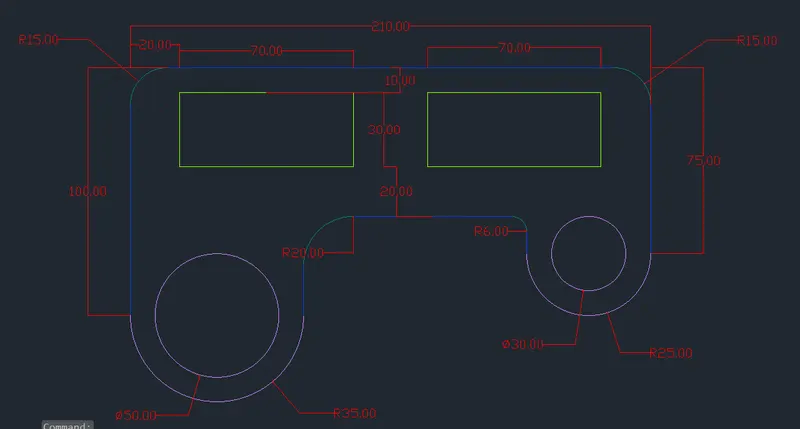
- FIGURE-7
- Steps:
- Type L to select the line tool and specify the first point.
- Specify the coordinates as "@100<90; @210<0; @75<270; @210<180".
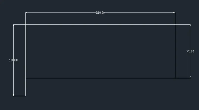
- Type O to select the offset tool and draw the top horizontal line at distances 10, 40, and 60.
- Again select the offset tool and draw both the vertical lines at distances of 20 and 90.
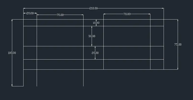
- Type TR to select the trim tool.
- Trim and extend the lines as per the requirement.
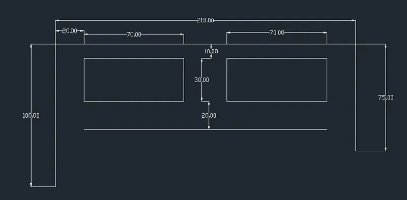
- Type C in the command box to draw two concentric circles with radii specified as 25 and 35.
- Again select the circle tool to draw two more concentric circles with radii specified as 15 and 25.
- Select the circles and move them with the move tool and keep them at the specified corners of the figure.
- Type L to select the line tool and then type TAN to draw tangents, then click on the outer circles and the bottom horizontal line.
- Type F to select the fillet tool.
- Specify the fillet radius as 15.
- Select the left vertical line and top horizontal line and repeat the process with the right vertical line and top horizontal line.
- Again select the fillet tool and specify the radius as 20 and select the tangent line from the left circle and bottom horizontal line.
- Repeat the process with the tangent of the right circle and the bottom horizontal with the specified radius of 6.
- Type TR in the command box to trim the unnecessary parts of the figure.
- RESULT:
- FIGURE-8
- Steps:
- Type L to select the line tool and specify the first point and distance of 8.55.
- Type C to select the circle tool and take the mid-point of the line as the center of the circle and draw two concentric circles with radii 2 and 2.5.
- Again select the circle tool and draw two concentric circles with radii 0.45 and 0.90 on the left and proper ends of the line.
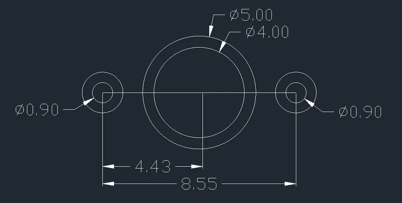
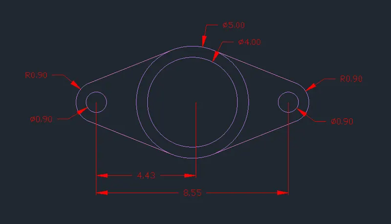
- Select the line tool and then type TAN to draw tangents around the circles.
- Select the trim tool to trim the lines not-required.
- RESULT:
- FIGURE-9
- Steps:
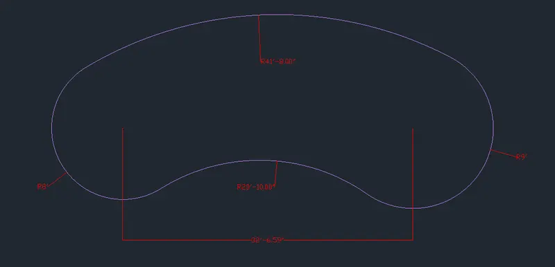
- Type L to select the line tool and draw a line of 32'65".
- Select the circle tool and draw a circle of radius 8' on the left end of the line.
- Again, select the circle tool and draw a circle of radius 9' on the right end of the line.
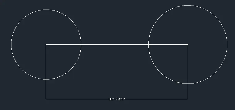
- Select the circle tool and the type of circle option as TAN TAN RADIUS.
- Select the first circle and the second circle and specify the radius of 41'8".
- Again, select the circle tool and the type of circle option as TAN TAN RADIUS.
- Select the first circle and the second circle and specify the radius of 21'10".
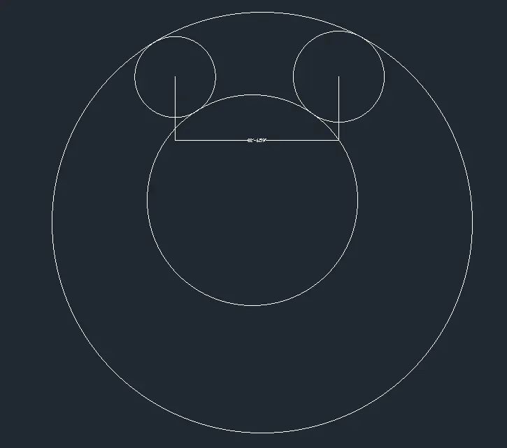
- Type TR in the command box to select the trim tool.
- Draw dimensions.
- RESULT:
- FIGURE-10
- Steps:
- Type REC to select the rectangle tool.
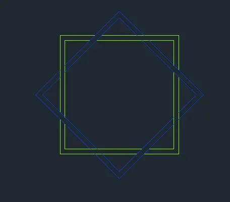
- Select the option Dimensions and specify the length and width as 2'.
- Type O to select the offset tool and specify the distance at 1".
- Offset the square inside.
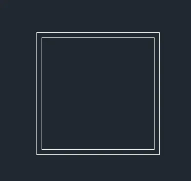
- Select the rotate tool.
- Select the copy option in the rotate tool.
- Select the objects to be rotated.
- Specify the center as the base for rotation.
- Specify the rotation angle as 45 degrees.
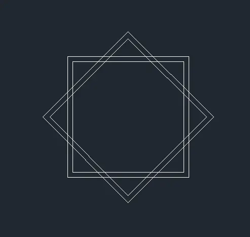
- RESULT:
- FIGURE-11
- Steps:
- Type L in the command box to select the line tool and specify the first point.
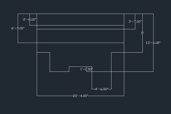
- Specify the next coordinates as "@20'4"<0; @9'<270; @2'8"<180; @4'6"<270; @4'6"<180; @1'2"<90; @5'4"<180; @1'2"<270; @4'6"<180; @4'6"<90; @2'8"<180 and then type C".
- Type O in the command box to select the offset tool and offset the top horizontal line at the distances of 2'8"; 3'7" and 6'9".
- Again select the line tool and draw two lines perpendicular to each other of length more than 4'.
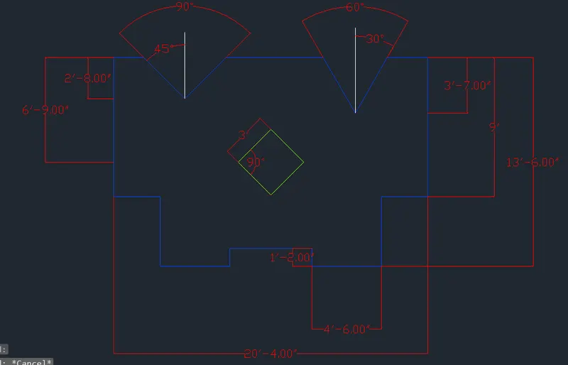
- Then select the rotate tool and rotate the lines by 45 degrees and place it by opting for the move tool on the offset line distanced at 2'8".
- Then again draw two lines at 60 degrees of length more than 5'.
- Then again select the rotate tool and rotate the lines by 60 degrees and place it by opting for the move tool on the offset line distanced at 3'7".
- Type REC in the command box to select the rectangle tool.
- Select the Dimensions option and specify the length and width as 3' to draw a square.
- Then rotate the square by 45 degrees with rotate tool.
- Place the square at the intersection point.
- Specify the dimensions.
- RESULT:
- RESULT:- THESE CHAMFER AND FILLET TOOLS IN THE AUTOCAD ENABLE THE DESIGNER TO PROVIDE VARIOUS BEAUTIFUL DESIGNS WITH THE HELP OF EDITING THROUGH VARIOUS OPTIONS SUCH AS DIMENSIONS, RADIUS, AREA, ANGLE, AND DISTANCE BY WHICH THE FIGURES CAN BE MANEUVERED.