Creating a Floor plan, Footing detail and Isometric view using AutoCad
- Aim:- Creating a Floor plan, Footing detail, and Isometric view using AutoCAD.
- Introduction:- This project has drawings in which most of the commands are used which are useful to make drawings easier to draw on AutoCAD and also introduces the use of the isometric plane.
- Use of the Line command with ortho ON/OFF.
- Use of copy command.
- Use of Array option in copy command.
- Use of Trim/Extend command.
- Use of Isometric drafting.
- Use of Polar tracking.
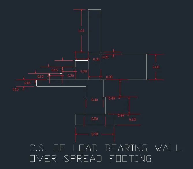
- FIGURE-1
- Steps:
- Type L in the command box and press enter to select the Line command.
- Specify the first point of the line.
- To draw the footing part, specify the next coordinates as @0.40<0; @0.40<270; @0.05<0; @0.40<270; @0.20<0; @0.25<270; @0.90<180; @0.25<90; @0.20<0; @0.40<90; @0.05<0; @0.40<90.
- Now, to draw the bearing wall part again select the line tool and specify the first point at the top right corner of the footing.
- Specify the next coordinates as @1<0; @0.60<90; @1.05<180; @1.05<90; @0.30<180; @1.15<270; @0.30<180; @0.15<270; @0.30<180; @0.15<270; @0.30<180; @0.15<270; @0.30<180; @0.15<270; @1.25<0.
- Type O to select the offset tool.
- Select the top line of the wall and offset it at the distance of 1 downwards.
- Extend the required lines.
- Specify the dimensions.
- RESULT:
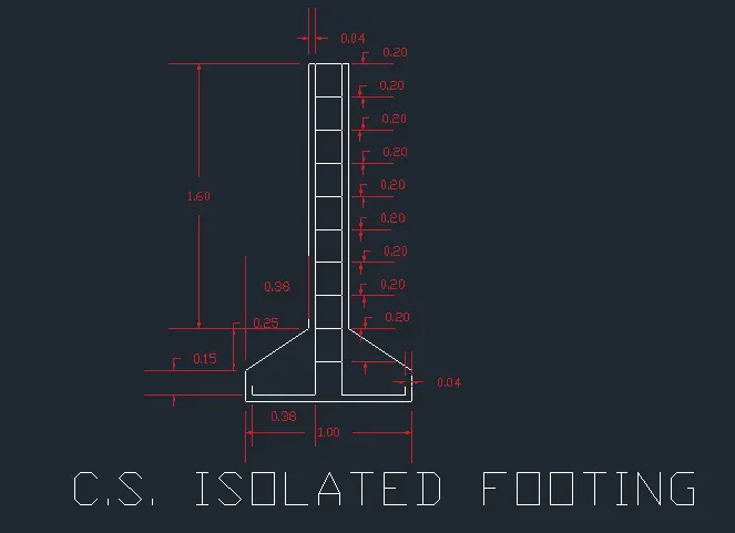
- FIGURE-2
- Steps:
- Type L in the command box to select the line tool and draw a horizontal line of 1 unit.
- Type O in the command box to offset the line.
- Offset the line at 0.04.
- Again offset the line at 0.15 and then again at 0.25.
- Again select the line tool.
- Draw the vertical lines of 0.19 units on right and left sides of the horizontal lines.
- Offset these vertical lines at 0.04 units.
- Again offset the inner vertical lines at 0.38 units.
- Join the vertical lines with a 0.16 units horizontal line.
- Copy the 0.16 units line and select the Array option, specify the number of array times as 10 and specify the array distance at 0.20 units and place them vertically.
- Join the copied lines with vertical lines on both sides.
- Offset the lines at 0.40 units.
- Draw the inclined lines as per the requirement.
- Trim the non-required lines.
- Specify the dimensions.
- RESULT:
- FIGURE-3
- Steps:
- Type XLINE in the command box to select the construction line command.
- Draw horizontal and vertical construction lines.
- Offset the vertical line at 3.60 units.
- Offset the horizontal line at 8.79 units.
- Trim the excess lines using the trim tool.
- Select the offset tool and offset the horizontal line at the distances of 4.19 and 1 unit.
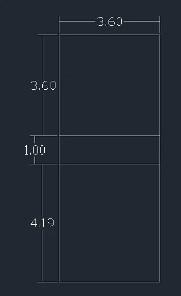
- To draw the steps offset the vertical lines at the distance of 0.30 units on both sides.
- Select the extend tool and extend the required lines for drawing steps.
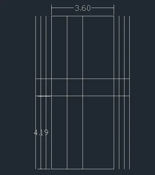
- Select the trim tool and trim the excess lines.
- Specify the dimensions.
- Label the drawing.
- RESULT:
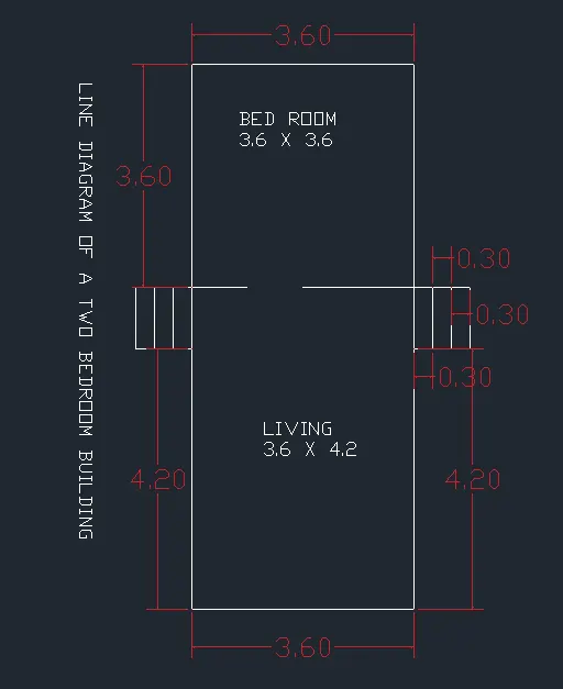
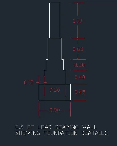
- FIGURE-4
- Steps:
- Type L in the command box to select the line tool.
- Draw a line of 0.90 units.
- Type O to select the offset tool.
- Specify the distances and offset the line at 0.45, 0.40, 0.30, 0.60 and 1 unit.
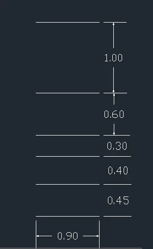
- Draw vertical lines on both the sides from top to bottom.
- Select the offset tool and offset the vertical lines at 0.15, 0.05, 0.05 and 0.05 units from both sides.
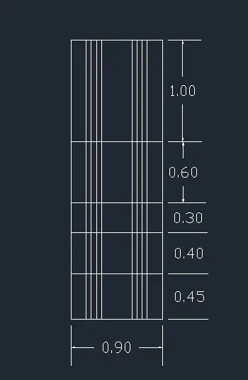
- Type TR in the command box to select the trim tool.
- Trim the non-required lines.
- Specify the dimensions.
- RESULT:
- FIGURE-5
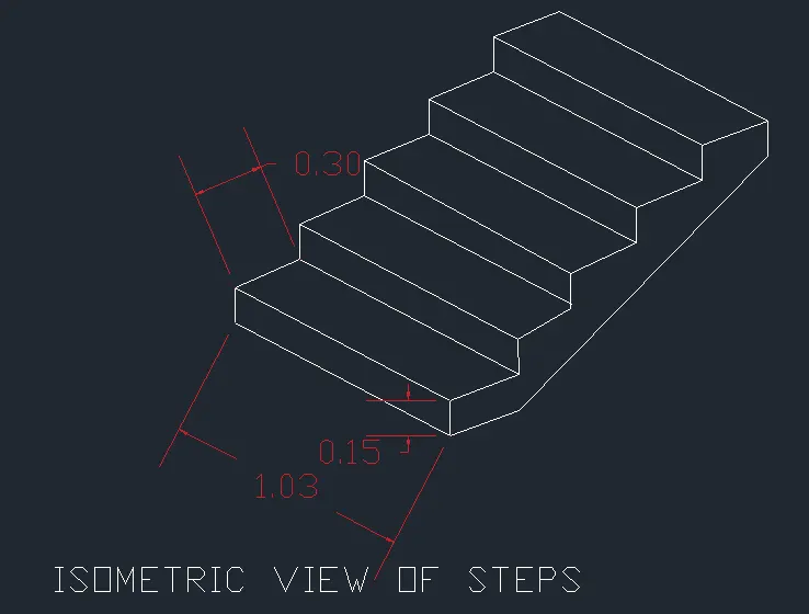
- Steps:
- Select the isometric drafting.
- Select the line tool.
- Draw a 1 unit line at 165 degrees.
- Then continue the line at 90 degrees of 0.15 units.
- Then continue the line at 15 degrees of 0.30 units.
- Repeat the step-4 and step-5, 4-times.
- Then specify the distance as 1 unit and draw a line at 315 degrees.
- Then continue the line at 270 degrees of 0.15 units and type C to close the picture.
- Draw parallel lines at 0.15 and 0.30 units.
- Join the lines to complete the figure.
- RESULT:
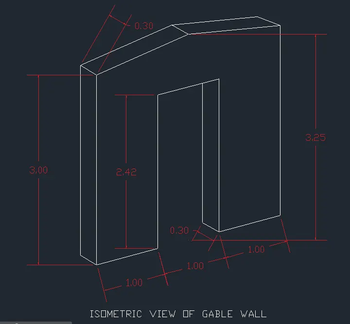
- FIGURE-6
- Steps:
- Select the isometric drafting option.
- Select the line tool and specify the first point.
- Draw a 3 units line at 90 degrees.
- Then a line perpendicular of 3 units, and then 3 units at 270 degrees.
- The a line at 195 degrees of 1 unit, and then of 2.42 units at 90 degrees.
- Then again at 195 degrees 0f 1 unit, and then of 2.42 units at 270 degrees.
- Close the figure.
- Again select the line tool and draw a line of 0.30 units at 165 degrees and copy the line at required points.
- Again select the line tool and join the lines to complete the figure.
- RESULT: