Drafting of various geometries using Chamfer, Fillet tool in AutoCad
Aim- To draw the geometry using decimal unit.
Commands Used-
- Line
- Dimstyle
- Units
- Offset
- Circle
Procedure-
- Select line command by typing "L" from keyboard and specify the origin of geometry (let's say 0,0)
- Specify the next point -@3,0
- Specify the next [email protected],<45
- Specify the next [email protected],<135
- Specify the next point-@-2,0
- Specify the next point-c
Select offset command and provide offset distance as 1and 1.5 in y direction. Next draw line from center of geometry in y direction. Hence we find the center of both circles.
Now Select circle command from ribbon tab and and Specify the center of circle with dia-1.2
Specify the center of next circle and provide dia -.80 in command box..
Now trim all the unwanted lines from the geometry.
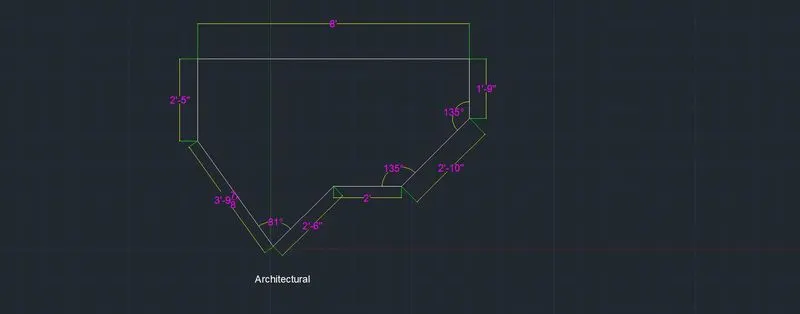
Result- Geometry has been drawn using decimal units.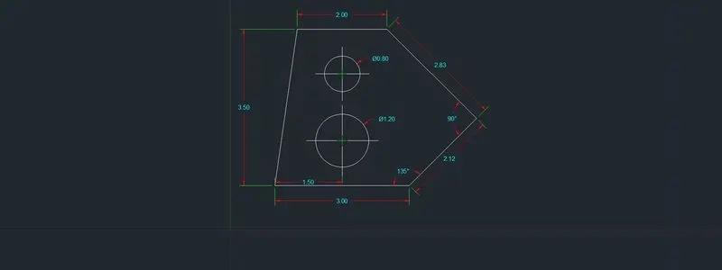
Aim- To draw geometry using architectural unit.
Commands used-
- Line
Procedure-
- specify the first point-(0,0)
- Specify the next point-@2'6"<40.5
- Specify the next point- @2',0
- Specify the next point- @2'10"<45
- Specify the next point- @1'9",<90
- Specify the next point- @-8,0
- specif the next point- @0,-2'5"
- specify the next point- c
Result- Geometry has been drawn using architectural unit.
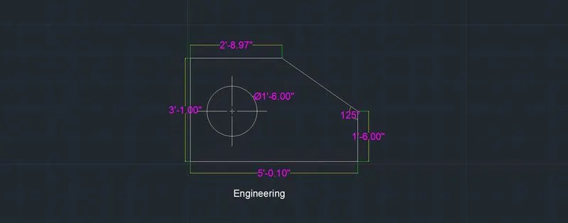
Aim- To draw the geometry using engineering unit.
Commands used-
- Line
- circle
- offset
procedure-
- Specify the first point lets say (0,0), using line command,
- Specify the next point-@5'.1",<0
- Specify the next point - @1'6",<90
- Specify the next point - @5',<155
- now press enter and esc.
- Select line command and specfy first point(0,0)
- specify the next point - @0,3'1"
- Specify the next point- @ 2'8.97",0
- press enter .
- select offset command and provide offset distance as 1'6" in y direction.
- repeat offset command and provide offset distnce of 1'3" in x direction to obtain centre of the circle.
- now select circle command and specify centre .
- select diameter of the circle - 1'6"
- now trim all the unwanted objects in the drawing.
Result- Geometry using engineering unit has been drawn.
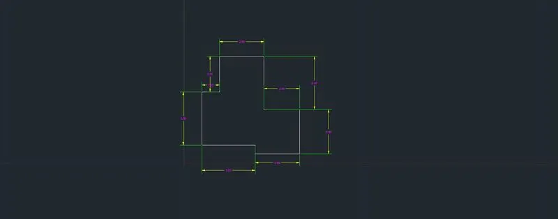
Aim- To draw the geometry using tools needed for drawing.
Command used -
- line
Procedure-
- select line command from ribbon tab.
- specify the first point-(1,1), make sure ortho mode is on
- specify the next point - 3 units in x direction
- specify next point - .5 in -y direction
- specify next point - 2.5in x direction
- specify next point - 2.5in y direction
- specify the next point- 2 units in -x direction
- specify the next point - 3 units in y direction
- specify the next point - 2.5 units in -x direction
- specify the next point - 2 units in -y direction
- specify the next point - 1 unit in - x dirextion
- specify the next point - c
- press enter
Result- The geometry has been drawn.
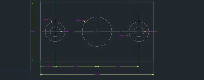
Aim - To draw the geomery.
Commands used-
- line
- circle
- offset
- trim
Procedure- select line command from ribbon tab.
- specify the first point-(0,0)
- Specify the next [email protected],0
- Specify the next point - @0,6
- Specify the next point- @-11.5,0
- Specify the next point- c
- select offset command and provide offset distance 1.5,4.25,4.25 in x direction,
- using offset distance 3 in y direction we have the center of all 3 circles.
- select circle command draw the circle of diameter 1 and 2, use copy command and select the circle,
- copy it on the another center point
- repeat circle command and specify diameter of the circle as 3 at the centre of the geometry.
- using trim command trim all the unwanted lines in th geometry.
Result- the geometry is drawn using line, circle, offset and trim command.
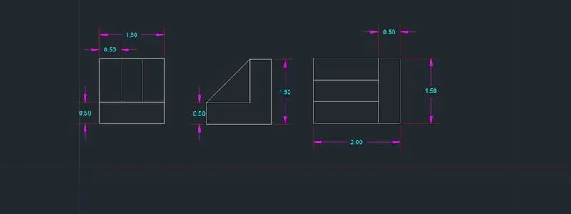
Aim - To draw the geomery.
Commands used-
- line
- offset
- copy
- rotate
Procedure- select line command from ribbon tab.
- specify the first point-(0,0)
- Specify the next [email protected],0
- Specify the next point - @0,2
- Specify the next point- @-1.5,0
- Specify the next point- c
- select offset command
- specify offset distance .5 in y direction
- repeat offset and provide .5 offset distance in x direction.
- press enter and esc.
using copy command copy the geometry at some distance and use rotate command to rotate it.
select line command and specify the first point.
- Specify the next [email protected],0
- Specify the next point - @0,1.5
- Specify the next point- @-.5,0
- Specify the next point- @0,.1
- specify next point - @-1,0
- specify the next point-c
Result - The geometry is drawn using different commands.
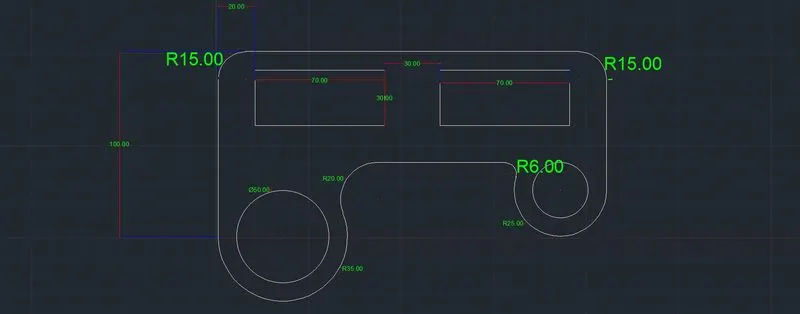
Aim- To draw geometry .
Commands used-
- circle
- offset
- line
- trim
- mirror
Procedure- select line command
- specify the first point-(0,0)
- Specify the next point - 4.275 in x direction
- Specify the next point -c
select circle command and draw a circle of diameter 4 and 5 on the right corner of the line.
repeat circle command and draw circle of diameter .9 and 9 radius on the left end of the line.
select polyline and tangent of the circles at the both end of the line.
select mirror command and mirror the object .
now select the trim command and trim all the unwanted lines and part of circles from geometry.
Result- the geometry is drawn.
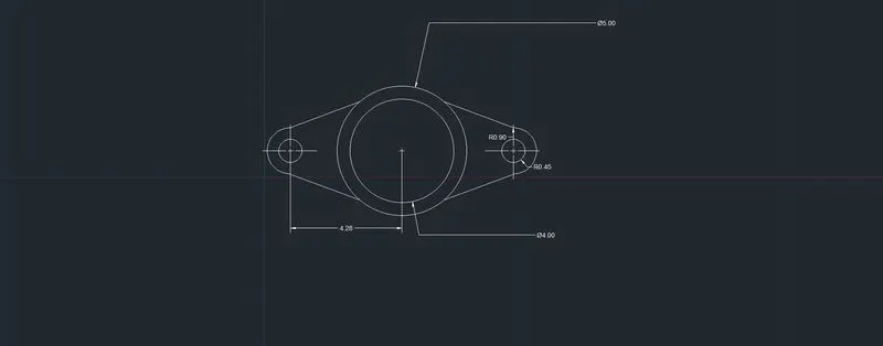
Aim- To draw geometry .
Commands used-
- circle
- offset
- line
- trim
- fillet
Procedure- select line command
- specify the first point-(0,0)
- Specify the next point-@32'6",0
- Specify the next point -c
select circle command and draw a circle of diameter 16' on the left corner of the line.
repeat circle command and draw circle of diameter 18' on the right end of the line.
select filet command and provide fillet radius of 20'10" for bottom of circle and 41'8" for the top of circle.
using tream command trim all the unwanted part of the circle.
Result- Geometry has been drawn .
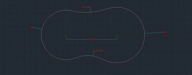
Aim- To draw geometry .
Commands used-
- offset
- line
- copy
- rotate
Procedure- select rectangle command by typing rec
- specify the first point-(0,0)
- Specify the length - 5
- Specify the wdth - 5
- press enter.
- select offset command and provide offset distance as.2 for rectangle.
- using copy command copy the geometry and using rotate command rotate the geometry in 45 degree.
Result- The geometry is drawn.
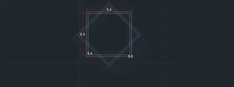
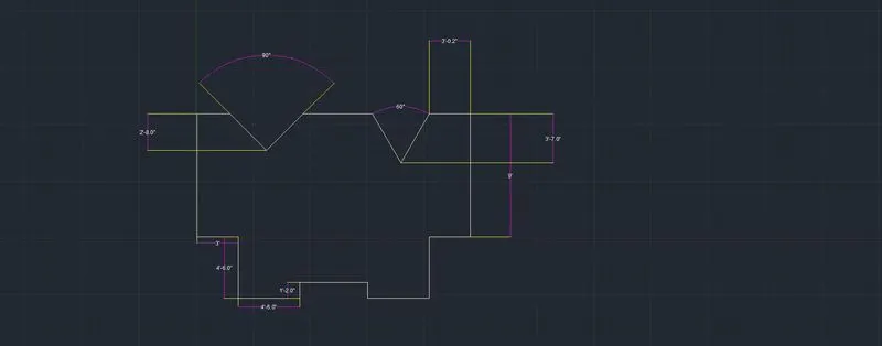
Aim - To draw the geomery.
Commands used-
- line
- offset
- copy
- trim
Procedure- select line command from ribbon tab.
- specify the first point-(0,0)
- Specify the next point-@3',0
- Specify the next point - @0,4'6"
- Specify the next point- @4'6",0
- Specify the next point- @0,1'2"
- Specify the next point-@5',0
- Specify the next point - @0,-1'2"
- Specify the next point- @4'6",0
- Specify the next point-@0',4'6"
- Specify the next point - @3,0"
- Specify the next point- @0,9'
- Specify the next point- @-20',0
- Specify the next point-c
- select offset command
- specify offset distance 2'8" in- y direction,5' in x direction
- repeat offset and provide 3'7"offset distance in y direction and 5' in -x direction.
- select line command and draw angles of 90 and 60 degree in the drawing.
- use trim command to trim all the unwanted lines in the geometry.
Result- The geometry has been drawn.