Creating a Floor plan, Footing detail and Isometric view using AutoCad
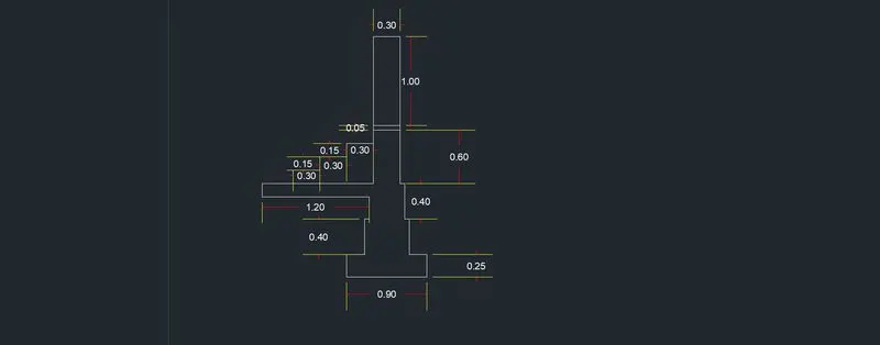
Cross section of load bearing wall over spread footing.
Aim: To draw cross section of wall over footing.
Commands used:
- Line
- offset
procedure:Select line command by typing 'L' on keybord.
Specify first point: (2,2), After specifying the first point lets use relative coordinate system to draw footing.
Specify next point : @.90,0
Specify next point : @0,.25
Specify next point : @-.20,0
Specify next point : @0,.40
Specify next point: @-.05,0
Specify next point: @0,.40
Specify next point : @-.05,0
Specify next point : @0,1.65
Specify next point : @-.3,0
Specify next point : @0,-1.65
Specify next point : @-1.25,0
Specify next point : @0,-.15
Specify next point : @1.2,0
Specify next point : @0,-.25
Specify next point : @-.05,0
Specify next point : @0,-.4
Specify next point : @-.2,0
Specify next point : C
Select Command: _line
Specify first point: 2.3,3.5
Specify next point : @-.3,0
Specify next point : @0,-.15
Specify next point : @-.3,0
Specify next point : @0,-.15
Specify next point : @-.3,0
Specify next point : @0,-.15
Specify next point :c
Select Command: _line
Specify first point: (2.3,3.65)
Specify next point : @.3,0
Select Command: OFFSET
Specify offset distance :0.5
Specify second point: .05
Result: The cross section of load bearing wall is drawn.
Cross section of an isolated footing.
Aim: To draw cross section of an isolated footing .
Commands used:
- line
- offset
Procedure: Select line command from keyboard by typing shortcut "L"
Specify first point: 1,1
Specify next point : @1,0
Specify next point : @0,.15
Specify next point : @-.38,.40
Specify next point : @0,1.6
Specify next point : @-.24,0
Specify next point : @0,-1.6
Specify next point : @-.38,-.4
Specify next point : C
After drawing outter elements of drawing let's select another point using line command,
Specify first point: (1.04,1.04)
Specify next point : @.38,0
Specify next point : @0,2.11
Specify next point : @.16,0
Specify next point : @0,-2.11
Specify next point : @.38,0
Specify next point :c and escape.
to draw the elements i between the footing lets use offset command and provide offset distance as(.20).
and repeat the command as required.
Result: The cross section of an isolated footing is drawn.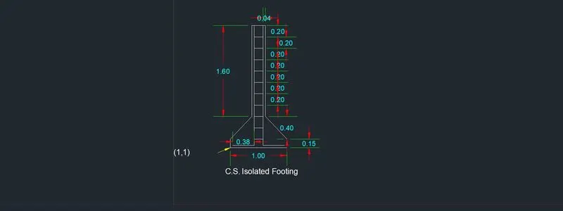
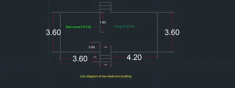
Aim:To draw line diagram of two bedroom building.
Command used:
- line
- offset
Procedure: Select line command using shortcut "L" from keyboard.
specify first corner :(1,1)
- using relative coordinate system specify next point:@3.6,0
- specify next point :0,-.9
- specify next point:1,0
- specify next point:0,.9
- specify next point:4.2,0
- specify next point:0,3.6
- specify next point:-4.2,0
- specify next point:0,.9
- specify next point:-1,0
- specify next point:0,-.9
- specify next point:0,-3.6
- specify next point :c
using offset command select offset distance as (.3) and repeat it two times in -y direction and two times in y direction.
select line command and specify:(4.60,1)
- specify next point: @0,.9 (press enter ad esc)
select line command and specify:(4.60,4.60)
- specify next point :@0,-1.8
- press enter and esc.
Result:Line diagram of two bedroom building is drawn.
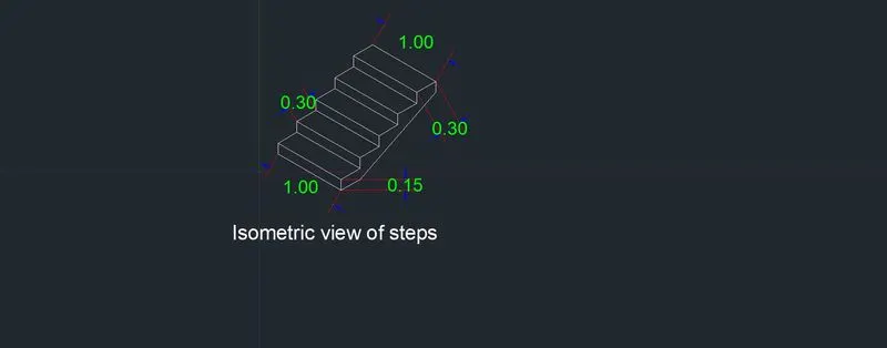
Aim: To draw isometric view of steps.
Commands used:
- isometric plane.
- lines
Procedure: To draw isometric drawing we use "ds"-snap off,grid off. And put isometric snap on.
- make ortho mode on.
- From isometric drafting select iso-plane left.
- Give command "l" and moving the cursor to -x direction give 1 unit.
- move the cursor to ydirection (top) and give.15 unit.
- move the cursor to x direction and give 1unit and cursor to y direction and give .15 unit (downward).
- Now change the isometric drafting to isoplan top.
- move the cursor back and give .3 unit ,move the cursor right and give 1 unit , again move the cursor front and give .3 units.
- use copy command and select all the elements , copy the selected object and specify the base point .
- repeat it until 5 steps are formed.
with isoplane right join the two ends with ortho off.
Result: The steps are drawn in isometric view.
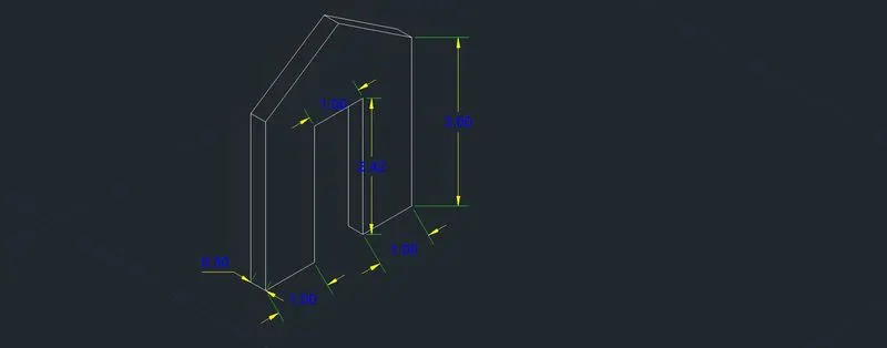
Aim: To draw isometric view of gabble wall.
Command used:
- line
- isometric plane
- trim
- ds
Procedure:To draw isometric drawing we use "ds"-snap off,grid off. And put isometric snap on.Command: line
Specify first point:(1,1)
Specify next point : .3
Specify next point : 3
Specify next point : .3
Specify next point : C
Command:
Command: _line
Specify first point:
Specify next point : 1
Specify next point : 2.42
Specify next point : 1
Specify next point : 2.42
Specify next point : .3
Specify next point : 2.42
enter
Command: _line
Specify first point:
Specify next point : 1
Specify next point : 3
Specify next point : .3
Specify next point or [Close/Undo]:c
Command: LINE
Specify first point:
Specify next point : 1.5
Specify next point : 4
Specify next point or [Close/Undo]:enter
Command: _line
Specify first point:
Specify next poin: .3
and now press esc
Command: TR (using this command trim all the unnecessary lines in the drwing.
Result: The ismetric view of gable wall is drawn.
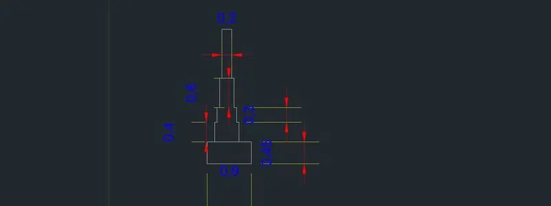
Aim: To draw the c/s of load bearing wall showing foundation details.
- Commands used: line
- rectangle
Procedure:
- create a rectangle by typing "REC" in command box.
- specify the first corner as :(1,1)
- specify the length of rectangle:0.9 units
- specify the width of the rectangle:.45 units
- use line command and specify first point:(1.15,1.45)
- specify the next point:@0,.4
- specify next point:@.05,0
- specify next point:@0,.3
- specify next point:@.05,0
- specify next point:@0,.6
- specify next point:@.05,0
- specify next point:@0,1
- specify next point:@.2,0
- specify next point:@0,-1
- specify next point:@.05,0
- specify next point:@0,-.6
- specify next point:@.05,0
- specfy next point:@0,-.3
- specify next point:@.05,0
- specify next point:@0,-.4
- specify next point:esc /enter
- select line command and specify the point:(1.3,2.75)
- specify the next point:.2,0
- specify the next point: esc/enter
Result: The cross section of load bearing wall showing foundation detail is drawn.