Creating a Residence Layout, Seating plan, Toilet and Utility room plan using AutoCad
P1. Residence Plan:
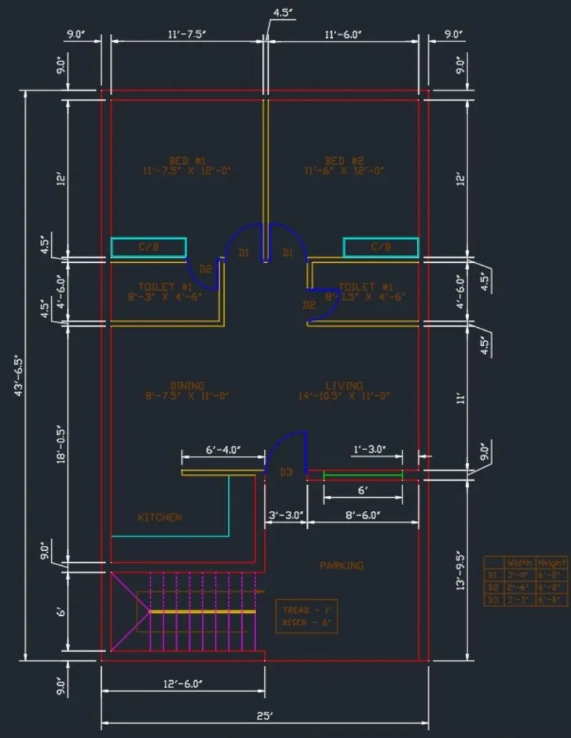
Sketch the layout of a residence as shown in the Figure 1. Consider all dimensions as reference to sketch the unit plan. Also the text in the layout are only for reference. Assume the missing dimensions. Also, refer the schedule for size of the doors.
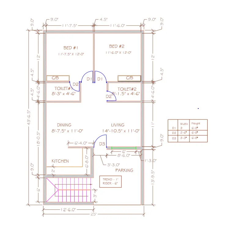
AIM: Sketch of the residence layout with help of autoCAD tools
Procedure:
Create a new drawing
Select metric in default settings
In advanced setup in units check on the engineering with precision 0'-00" and in insersion scale enter inches

In the command tab type xline ,specify the point,then click on the vertical and x y lines will be formed of length infinity
Next in the command tab type O i.e OFFSET and enter the distance as 9" and offset the horizontal line to top
Now in command tab type O and specify the offset distance of offset as 18'-0.5" and offset the horizontal line to op
In the command tab type O and specify distance of offset as 4.5" and offset the horizontal at the top
In the command tab type 0 and specify the distance 4.5" and offset the horizontal line to top
Now in the command tab type O and specify distance of offset as 12" and offset the horizontal line to top
Now in the command tab type 0 and specify the distance of offset 9" and offset the horizontal line to top.
Now in the command tab type 0 and specify the distance of offset 9" and offset the vertical line to right.
Now in the command tab type 0 and specify the distance of offset as 11'7.5" and offset the vertical line to top
Now in the command tab type 0 and specify the distance of offset as 4.5" and offset the vertical line to top
Now in the command tab type 0 and specify the distance of offset as 9" and offset the vertical line to top
Now in the command tab type 0 and specify the distance of offset 12'6" and offset the vertical line to top
Now select all the created objects and in the command tab type TRIM and trim all the unwanted lines.
Type ex in the command prompt extend all the required lines
For staircase draw the 3' line vertical and copy it with co command and array it with 9 objects in the spacing of the 1'
Draw live horizontal connecting the all vertical lines and join this line to corner with fillet command
Select the created lines in staircase and mirror it with horizontal line
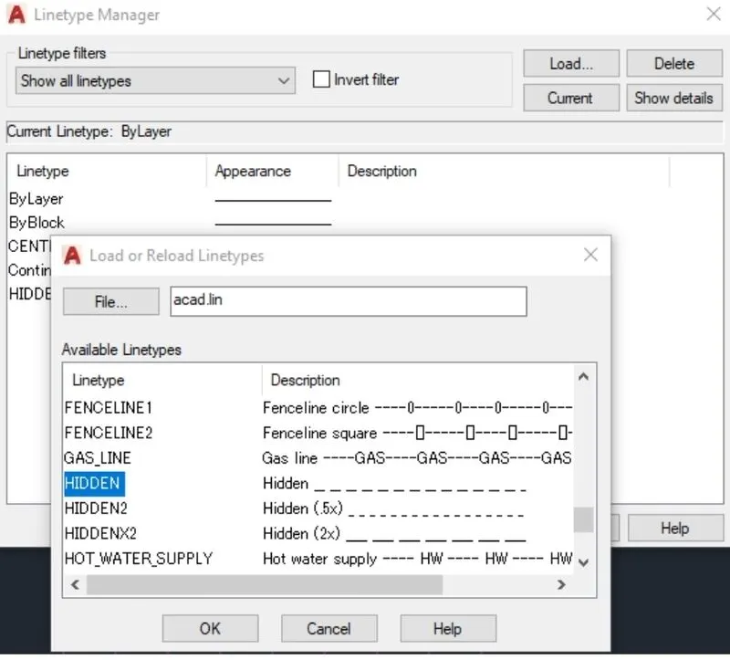
For the upper portion of stairs type LINETYPE and the window will appear . Search HIDDEN option and press OK
For doors D1,D2,D3 with the help of circle and trim the unwanted lines.
Type DIMSTY and change the units to engineering and change the text height as per required.
Now type DIM and specifying the points as per drawing.
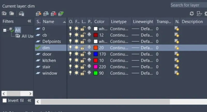
In the layer properties add all the required layers and with the QS quick selected tools assign the layers for the objects created.
Enter
2. Sketch the seating plan for an outdoor canopy. Assume the dimensions for the seating. Also, consider the dimensions in mm.
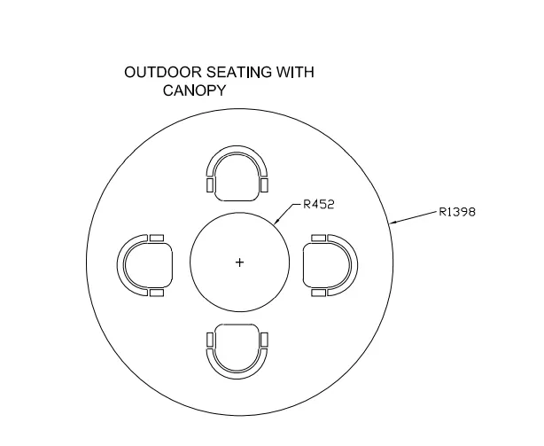
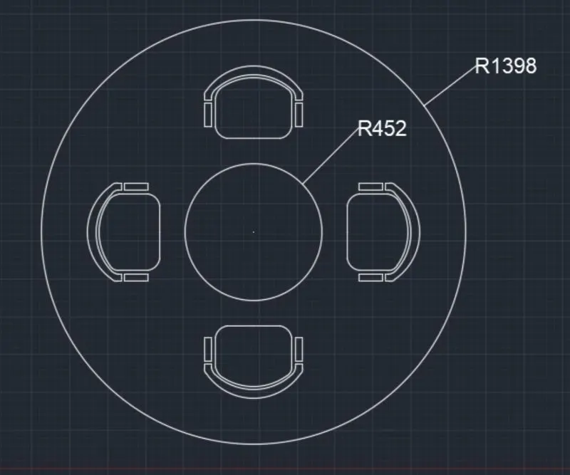
AIM: Sketching the AutoCAD outdoor canopy with the help of polar array tool
Procedure:
Create a new drawing
Select metric in default settings
In advanced setup in units check on the decimal with precision 0.00 and in insersion scale enter mm
In the command tab type CI where circle tool is introduced
Specify a point for the center and specify the radius 1398
With the same geometric center type CI and specify the point there and specify the radius 452
Enter
Type L command and create a recatangle 300*150 and the fillet top corners at an angle 45 and then offset them by 50
Copy it between both circle with the help of snapping and selecting them and clicking them in a circular array
Enter
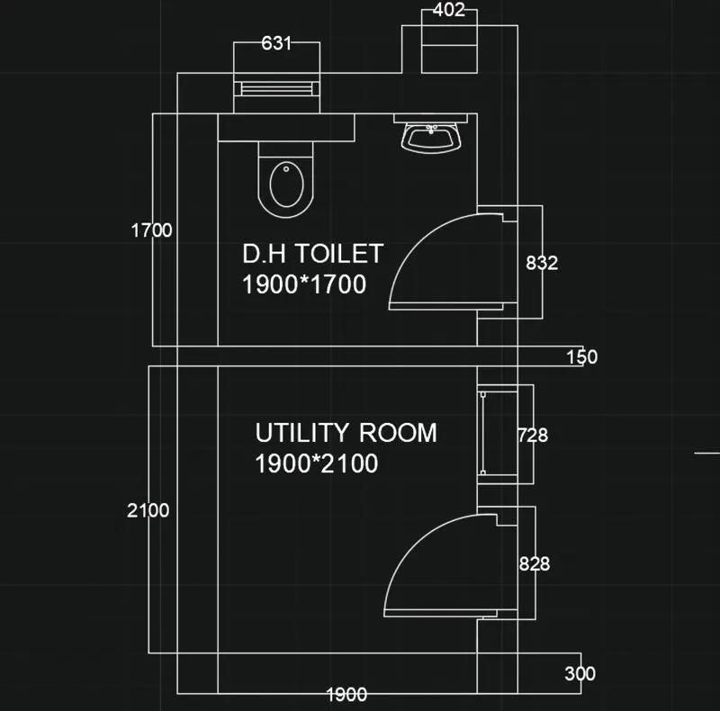
3. Sketch the part plan for the toilers and utilities room. Consider the outer wall thickness as 300mm and inner wall thickness as 150mm. Also, assume the missing dimension, Texts, dimensions, and hatches are only for references. Also, symbols for toilets and w/c are also for references.
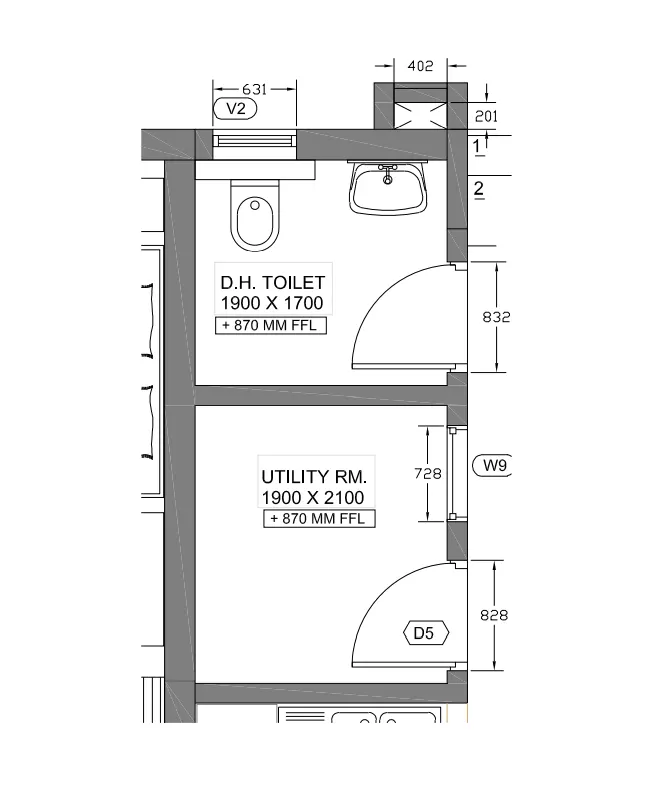
AIM: Sketching the layout in teh AutoCAD by assuming some assumptions
Procedure:
Create a new drawing
Select metric in default settings
In advanced setup in units check on the decimal with precision 0.00 and in insersion scale enter millimeter
In the command tab type xline ,specify the point,then click on the vertical and x y lines will be formed of length infinity
Next in the command tab type O i.e OFFSET and enter the distance as 300 and offset the horizontal line to top
Now in command tab type O and specify the offset distance of offset as 2100 and offset the horizontal line to top
In the command tab type O and specify distance of offset as 150 and offset the horizontal to the top
In the command tab type 0 and specify the distance 1700 and offset the horizontal line to top
Now in the command tab type O and specify distance of offset as 210 and offset the horizontal line to top
Now in the command tab type 0 and specify the distance of offset 150 and offset the horizontal line to top.
Now in the command tab type 0 and specify the distance of offset 300 and offset the vertical line to right.
Now in the command tab type 0 and specify the distance of offset as 1900 and offset the vertical line to right
Now in the command tab type 0 and specify the distance of offset as 150 and offset the vertical line to right
Now select all the created objects and in the command tab type TRIM and trim all the unwanted lines.
Type ex in the command prompt extend all the required lines
Draw live horizontal connecting the all vertical lines and join this line to corner with fillet command
Select the created lines in staircase and mirror it with horizontal line
For doors D1,D2,D3 with the help of circle and trim the unwanted lines.
Type DIMSTY and change the units to decimal and change the text height as per required.
Now type DIM and specifying the points as per drawing.
In the layer properties add all the required layers and with the QS quick selected tools assign the layers for the objects created.
Enter