Creating a Residence Layout, Seating plan, Toilet and Utility room plan using AutoCad
Drawing -1:
Aim:
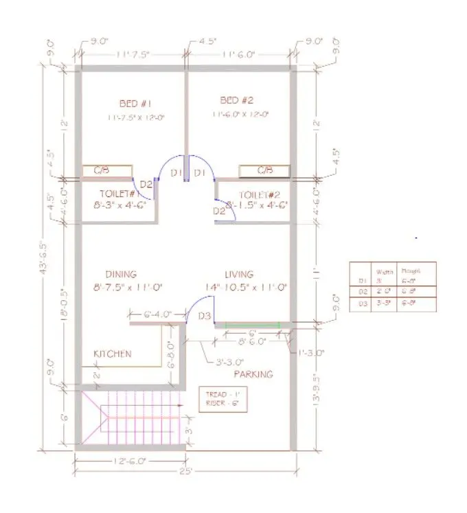
To sketch the layout of residential building by using Auto CAD and to give briefing about various commands used to draft this layout. And also give step by step procedure to complete this drawing.
Introduction:
XLine: It means construction line. It has infinty edges we used for making wall. By typing "XL" on command line we envoke this tool.
Line: It connects one point to another points. Used to draft various elements.
Trim: This modification tool helps to cut extended edges on the drawing. And to trim inbetween two line or elements. "TR" command to envoke this tool.
Extend: It is also a modification tool, if we have some broken edges or need to extend some portion towards anonther element. "EX" command to envoke the tool.
Offset: Offset the existing element with certain distance. this tool avoid to create new parallel elements.
Layer: Each and every elements has unique property and unique style. This layer tool helps to organize those. Line weight, line style, colour gradient, freeze, lock. it has numerous benefits in Auto CAD drafting.
Hatch: Hatching helps to fill the voids with certain texture on it. If we draft wall means, we mention the brickwork details with the help of hatching.
Circle: Used to make circle elements in the sheet. Type "C" to envoke this tool. Here it is used to draft door.
Procedure:
Step-1: Type "UN" to set units of the drawing sheet. " Engineering" and set precision "0'-0.0"".
Step-2: Type "LIMITS" to set size of the sheet we required to draft.
Step-3: Type "XL" to envoke construction line tool to plot vertical and horizontal lines.
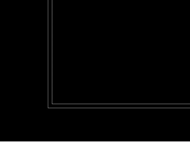
Step-4: TYpe "OFFSET" to draft outer wall thickness of 9" in both X and Y directions.
Step-5: Type "O" offset to continue given room size 6'0 and wall thickness 9" of the residential building.
Step-6: Type "O" offset to continue given room size 6'8" and wall thickness 4.5" of the residential building.
Step-7: Type "O" offset to continue given room size 11'0" and wall thickness 4.5" of the residential building.
Step-8: Type "O" offset to continue given room size 4'6" and wall thickness 4.5" of the residential building.
Step-9: Type "O" offset to continue given room size 12'0 and wall thickness 9" of the residential building.
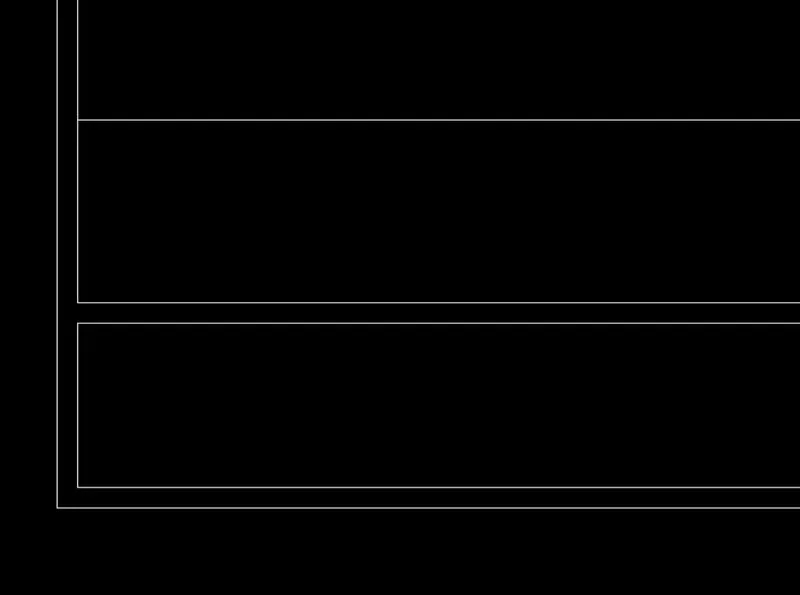
Step-10: Type "F" Fillet command to fillet the corner of the building with zero radius on it.
Step-11: Type "TR" Trim command to trim the extended lines on the drawing.
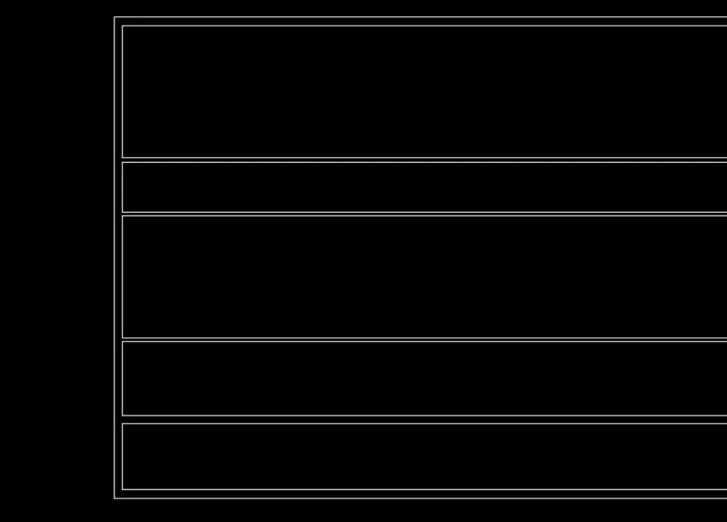
Step-12: Type "O" offset to plot X -direction also.
Step-13: Type "O" offset to continue given room size 12'6" of the residential building.
Step-14: Type "O" offset to continue given room size 6'4" of the residential building.
Step-15: Type "O" offset to continue given room size 8'3" and wall thickness 4.5" of the residential building.
Step-16: Type "O" offset to continue given room size 11'7.5" and wall thickness 4.5" of the residential building.
Step-17: Type "O" offset to continue given room size 11'6" and wall thickness 9" of the residential building.
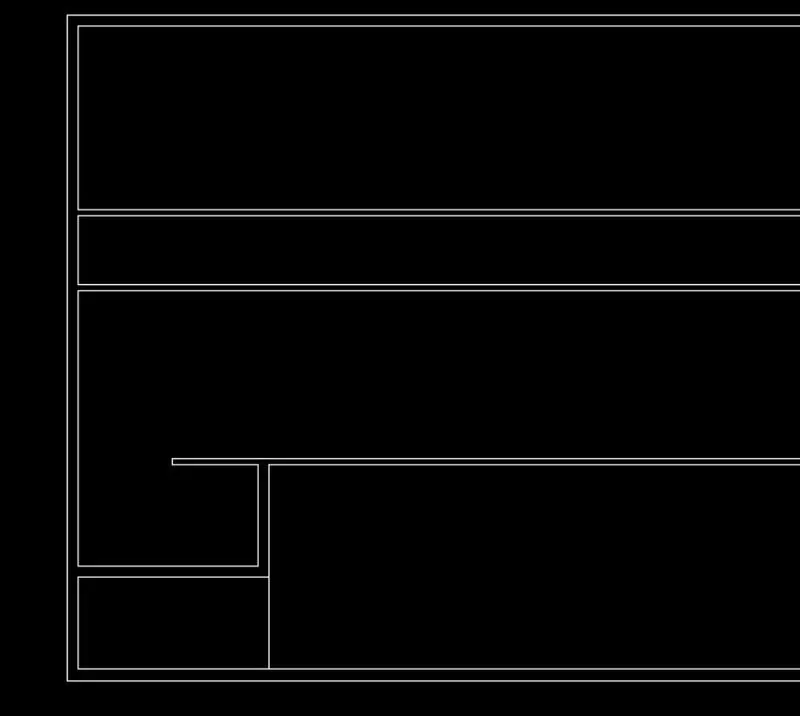
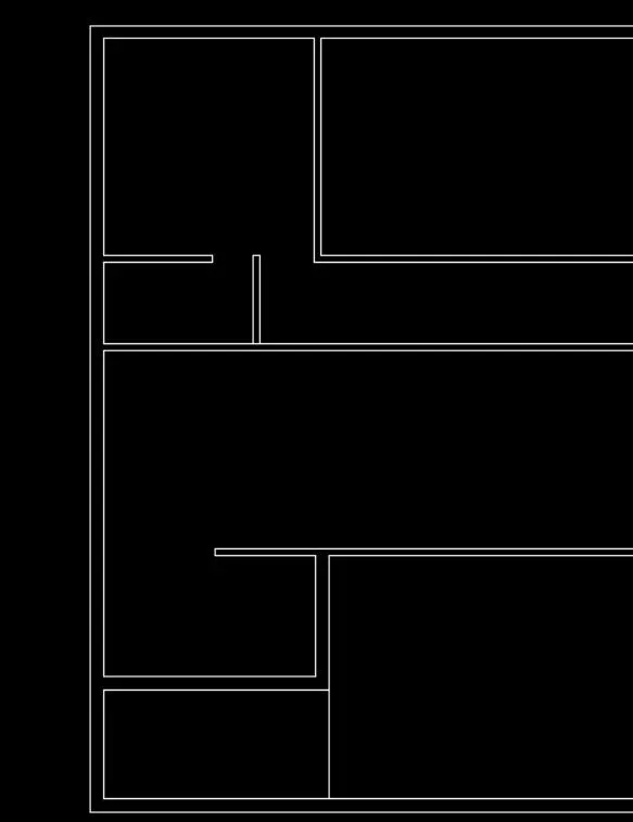
Step-18: Type "F" Fillet command to fillet the corner of the building with zero radius on it.
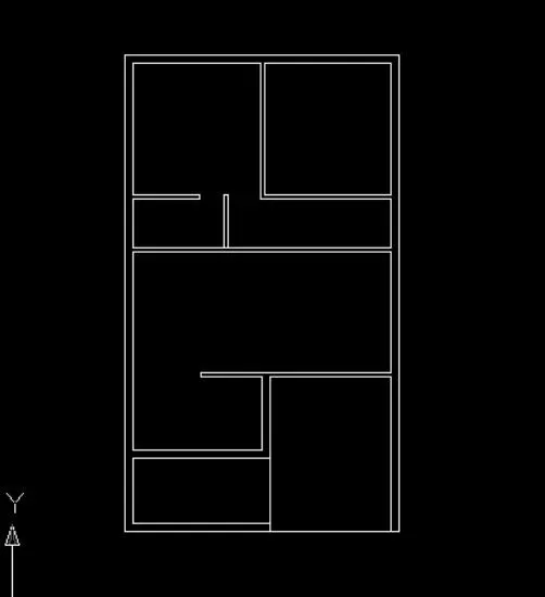
Step-19: Type "TR" Trim command to trim the extended lines on the drawing and intermediate line in between walls.
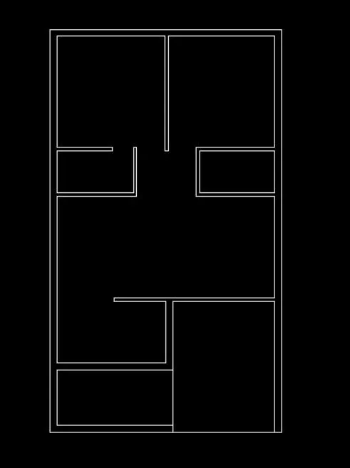
Step-20: Type "TR" to trim door openings and Type "L" to envoke line tool to plot staircase in the drawing.
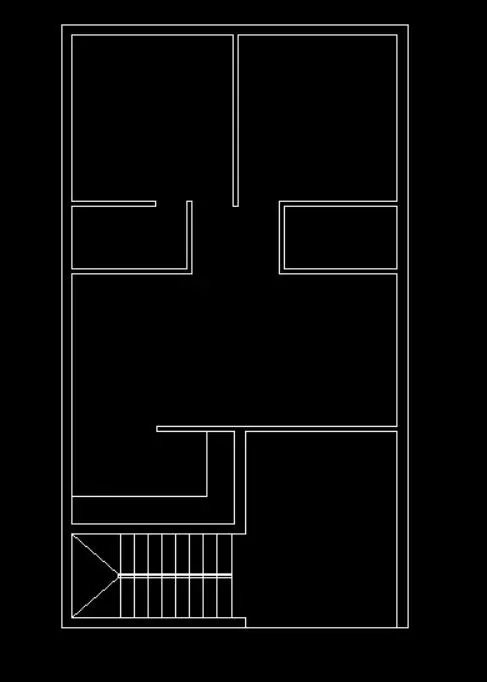
Step-21: Type "O" offset to continue Tread thickness of 1'0" .
Step-22: TYpe "L" to draw Wardrobe in the bedroom.
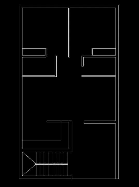
Step-23: Select from panel to change line color to differentiate the wall and stair. Use the layer tool to draft the elements.
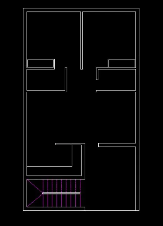
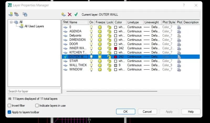
Step-24: Assaign the layer properties to all the elements in the drawing layout.
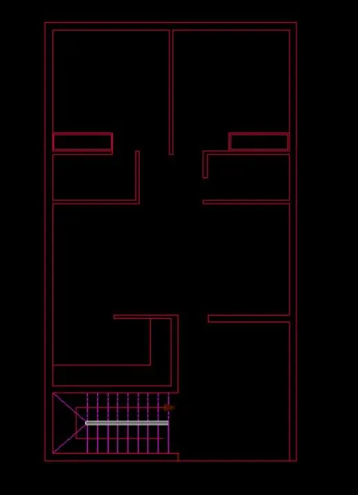
Step-25: Type "C" cricle used to draw the door with given measurement. and Type "B" block the door element.
Step-26: Type "CO" copy the door to paste to other opening with adjusted suitable width.
Step-27: Type "DIMLIN" to measure and mark the all linear dimensions in the sheet.
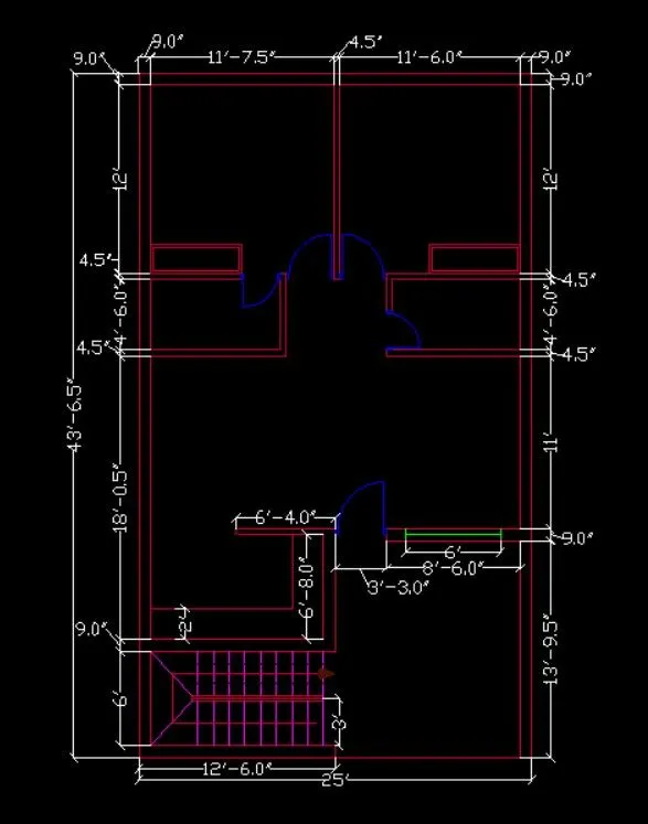
Step-28: Type "H" to envoke Hatch dialogue box to assign selected area for showing brickwork.
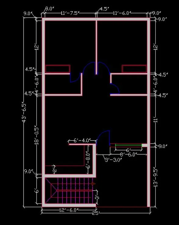
Step-29:
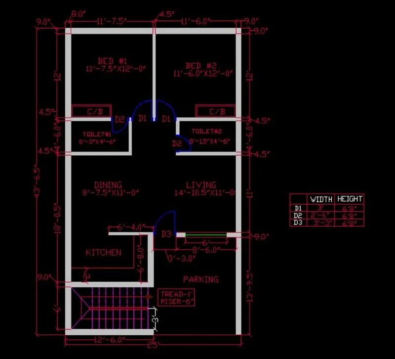
RESULT:
Sketch the layout of a residential building with given dimensions and taking the references from the text in the layout and also assuming the missing dimension to complete drafting. Joineries are drafting with helps details given in the Door and window agenda.
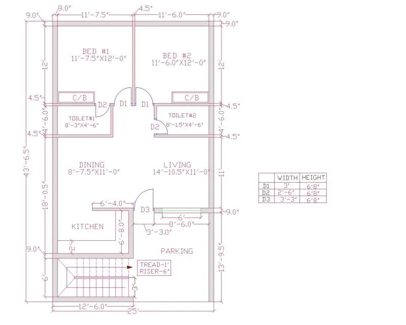
Drawing-2:
Aim:
To sketch the layout of outdoor seating with canopy by using Auto CAD and to give briefing about various commands used to draft this layout. And also give step by step procedure to complete this drawing.
Introduction:
Line: It connects one point to another points. Used to draft various elements.
Trim: This modification tool helps to cut extended edges on the drawing. And to trim inbetween two line or elements. "TR" command to envoke this tool.
Extend: It is also a modification tool, if we have some broken edges or need to extend some portion towards anonther element. "EX" command to envoke the tool.
Offset: Offset the existing element with certain distance. this tool avoid to create new parallel elements.
Layer: Each and every elements has unique property and unique style. This layer tool helps to organize those. Line weight, line style, colour gradient, freeze, lock. it has numerous benefits in Auto CAD drafting.
Circle: Used to make circle elements in the sheet. Type "C" to envoke this tool. Here it is used to draft door.
Arc: It is used to draw arc elements. Here it is helps to draw seatings.
Copy: It is used to copy the existing elements in the drawing pallete.
Mirror: It helps to mirror the exsiting objects with the help of base point. It reduces alot time to create another same object in mirrored way.
Rotate: It helps here to rotate the seating object with copy option to create new one.
Procedure:
Step-1: Type "UN" to set units of the drawing sheet. " Decimal" and set precision "0".
Step-2: Type "LIMITS" to set size of the sheet we required to draft.
Step-3: Type "C" to envoke Circle tool to plot circle with the radius of 1398 and another circle with 452 radius with the same center point.

Step-4: Type "L" to draw basic point for seating.
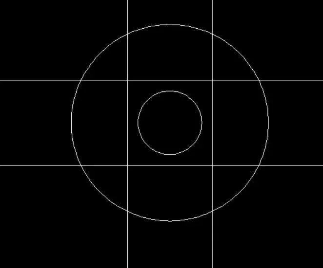
Step-5: Type "TR" to trim extended edges.
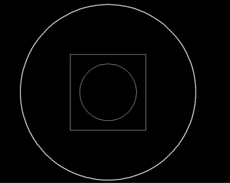
Step-6: Type "A" arc tool to draw circumference of seating.
Step-7: Type "O" offset with standard dimensions for cushion area.

Step-8: Type "L" to draft remaining elements.
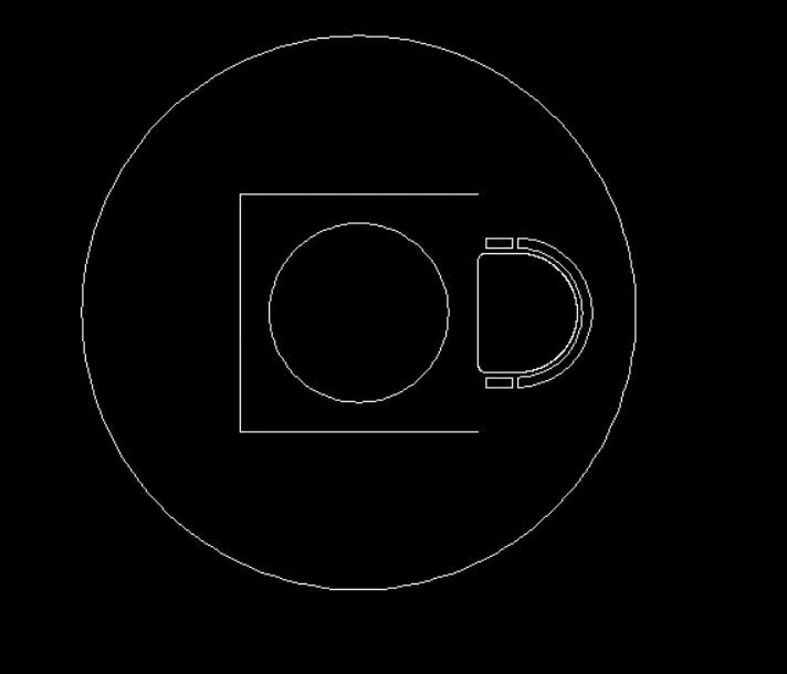
Step-9: Type "MI" mirror command to mirrored the existing seating element with the base point of circle center.

Step-10: Type "RO" rotate command to rotate the existing seating element with the base point of circle center and select "COPY" to create new and paste it at a angle of 90 degree.
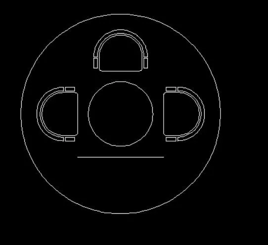
Step-11: Type "MI" mirror command to mirrored the existing seating element with the base point of circle center.
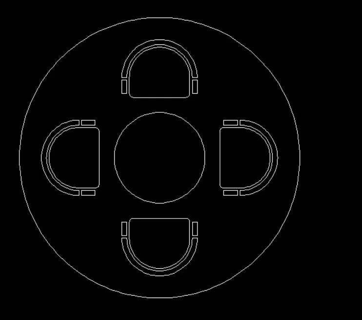
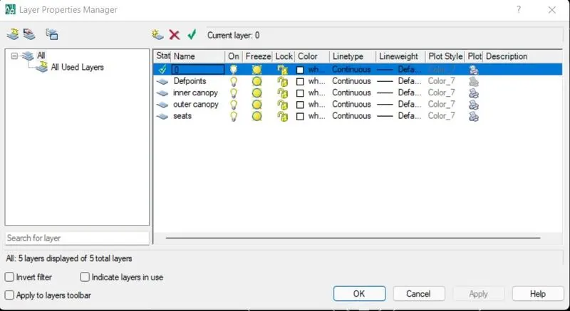
Step-12: Select Layer property manager to create respective layer for organizing elements in the drawing.
Step-13: Type "DIMRAD" to measure and mark the radius of the circle for future reference.
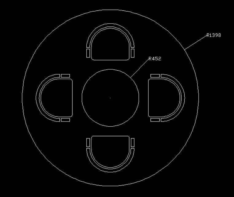
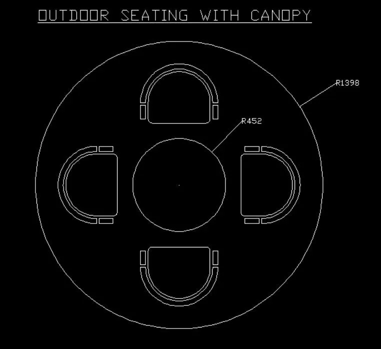
Step-14: Type "DT" to enter title of the project.
RESULT:
Drafting the seating plan for an outdoor canopy. Dimensions of the seating could be assumed.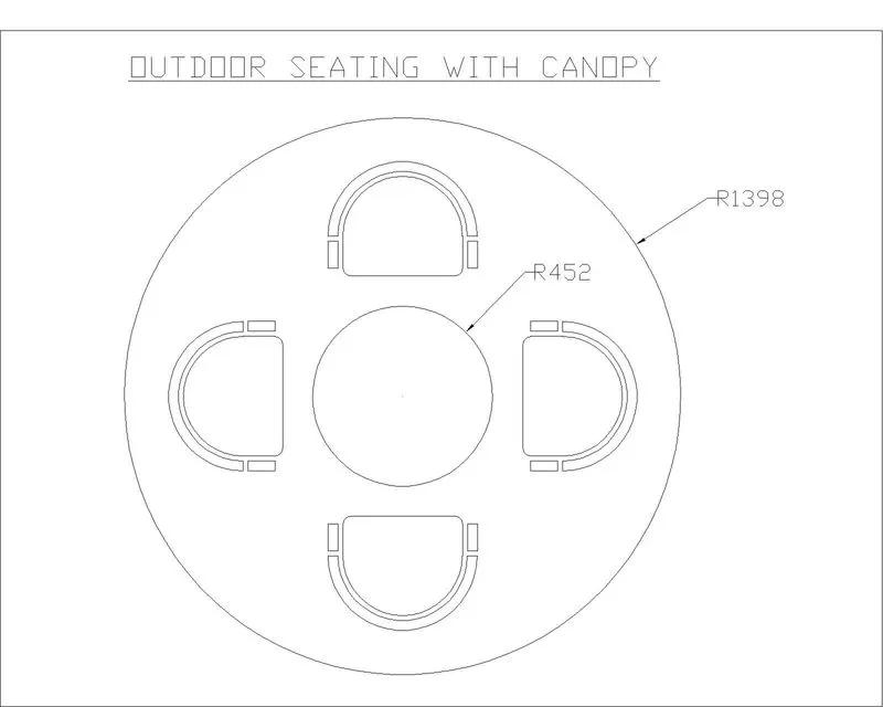
Drawing-3:
Aim:
To sketch the layout of residential building by using Auto CAD and to give briefing about various commands used to draft this layout. And also give step by step procedure to complete this drawing.
Introduction:
XLine: It means construction line. It has infinty edges we used for making wall. By typing "XL" on command line we envoke this tool.
Line: It connects one point to another points. Used to draft various elements.
Trim: This modification tool helps to cut extended edges on the drawing. And to trim inbetween two line or elements. "TR" command to envoke this tool.
Extend: It is also a modification tool, if we have some broken edges or need to extend some portion towards anonther element. "EX" command to envoke the tool.
Offset: Offset the existing element with certain distance. this tool avoid to create new parallel elements.
Layer: Each and every elements has unique property and unique style. This layer tool helps to organize those. Line weight, line style, colour gradient, freeze, lock. it has numerous benefits in Auto CAD drafting.
Hatch: Hatching helps to fill the voids with certain texture on it. If we draft wall means, we mention the brickwork details with the help of hatching.
Circle: Used to make circle elements in the sheet. Type "C" to envoke this tool. Here it is used to draft door.
Arc: It is used to draw arc elements. Here it is helps to draw seatings.
Copy: It is used to copy the existing elements in the drawing pallete.
Mirror: It helps to mirror the exsiting objects with the help of base point. It reduces alot time to create another same object in mirrored way.
Rotate: It helps here to rotate the seating object with copy option to create new one.
Procedure:
Step-1: Type "UN" to set units of the drawing sheet. " Decimal" and set precision "0".
Step-2: Type "LIMITS" to set size of the sheet we required to draft.
Step-3: Type "XL" to envoke construction line tool to plot vertical and horizontal lines.
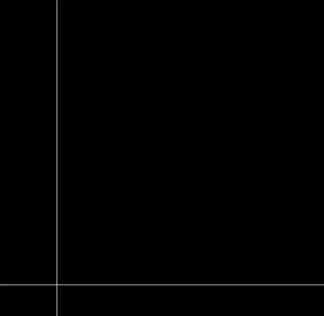
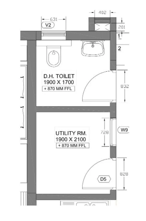
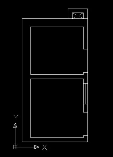
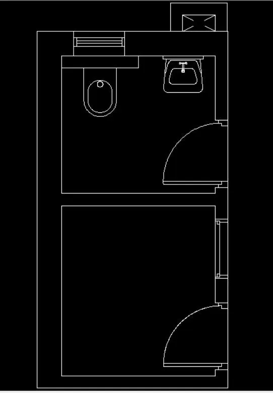
Step-4: Type "O" offset to make width (300 mm) of the wall and draft room dimensions 2100 mm.
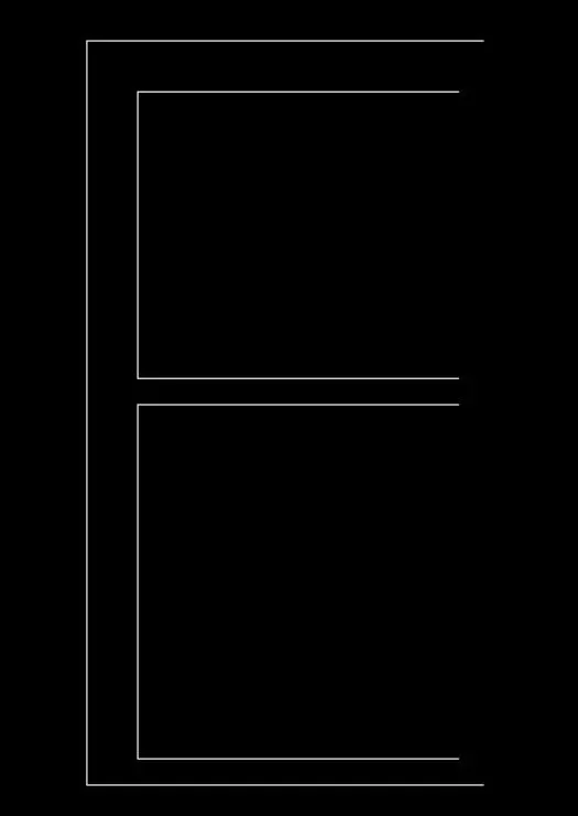
Step-5: Type "O" offset to make width (150 mm) of the wall and to draft room dimensions 1700 mm.
Step-6: Type "O" offset to make width (300 mm) of the outer wall.
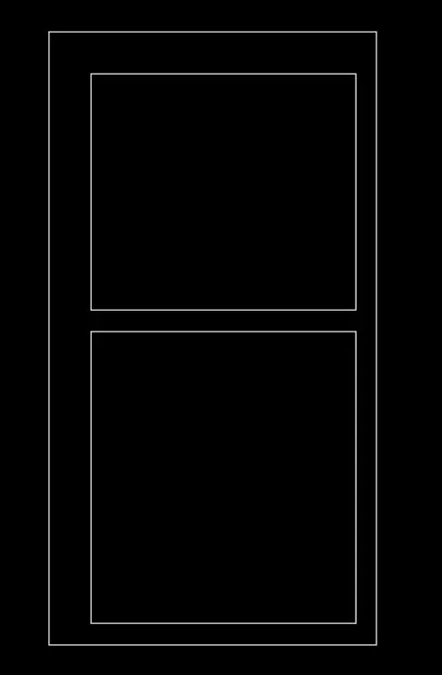
Step-7: Type "L" to draft ventilation area with given dimension of 201 mm at X-direction and 402 mm at Y- direction.
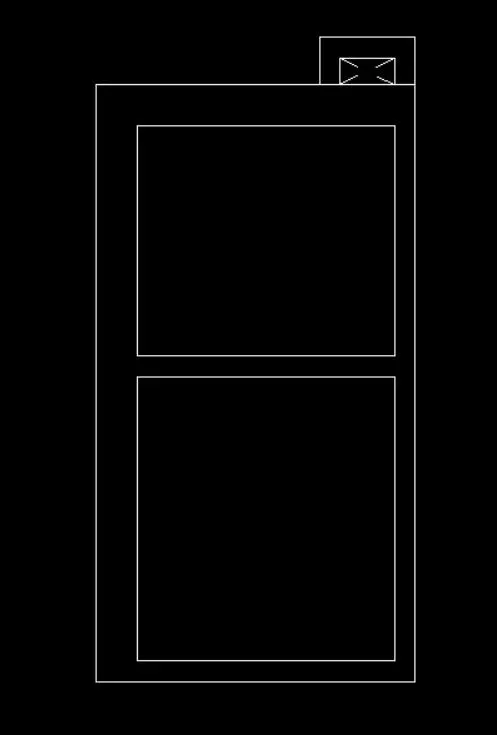
Step-8: Type "TR" Trim command to draft door opening at 828 and 832 in two rooms.
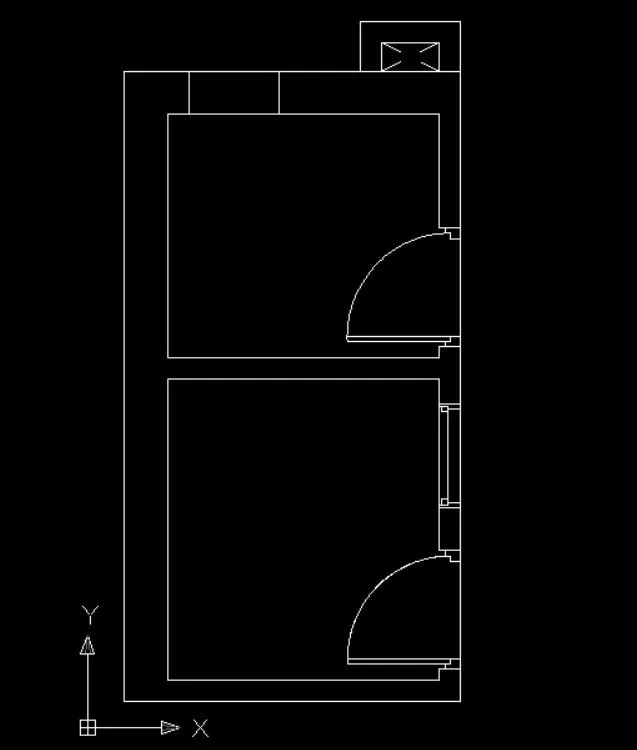
Step-9: Type "C" circle to draft door elements.
Step-10: Type "L" to draw window elements.
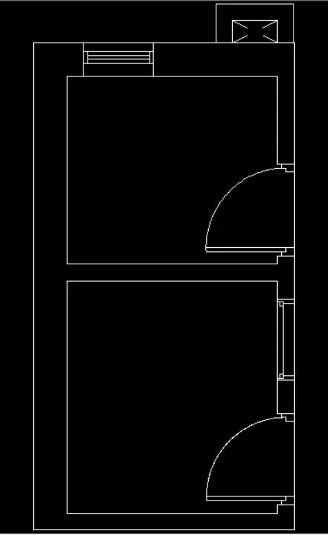
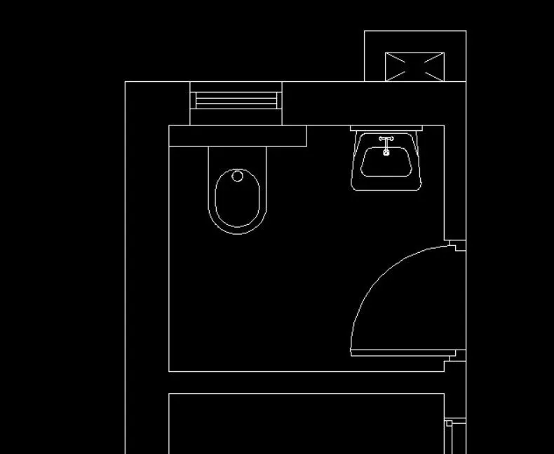
Step-11: Type "A" Arc to draw toilet seat and closet elements.
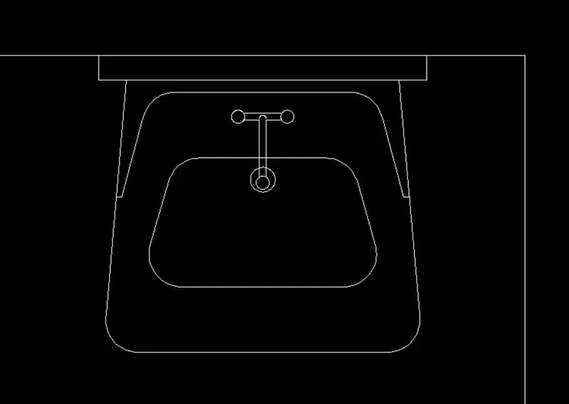
Step-12: Type "C" Circle to draw water tap elements.
Step-13: Type "L" to draw remaining elements of toilet.
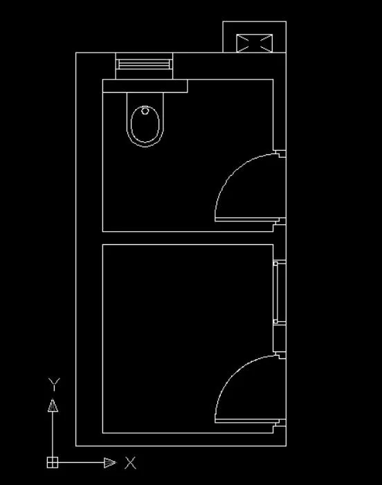
Step-14: Type "L" to draw wash basin elements.
Step-15: Type "A" arc to draw basin top elements.
Step-16: Type "O" offset to draw other portions elements.
Step-17: Type "H" Hatch to fill the wall infill.
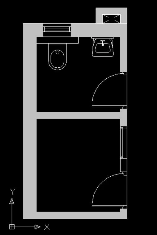
Step-17: Select Layer panel to create respective layer for organizing the elements.
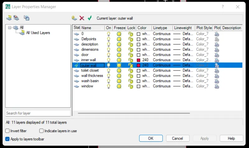
Step-18: Type "DIMLIN" to measure and mark linear dimensions on the given drawing.
Step-19: Type "DT" to mention description of rooms.
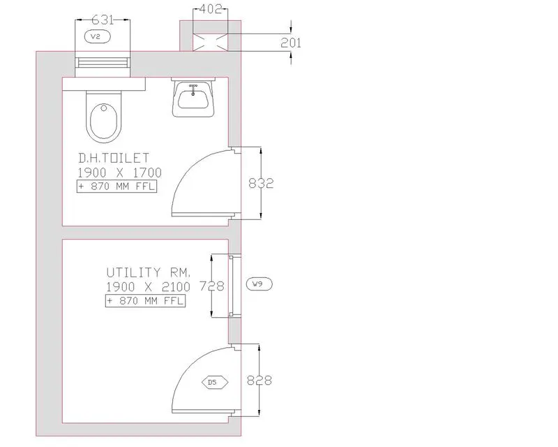
RESULT:
Draft the part plan of the building and toilets and utilities room. Missing dimensions and wall infill was provided given in the question and draft the toilet seat and wash basin also.