Drafting of various geometries using Chamfer, Fillet tool in AutoCad
AIM: To draw the various geometries using Chamfer, Fillet tool in AutoCAD.
Commands used: Line, Circle, Chamfer, Fillet, Offset, Trim, Move, Rotate.
Procedure:
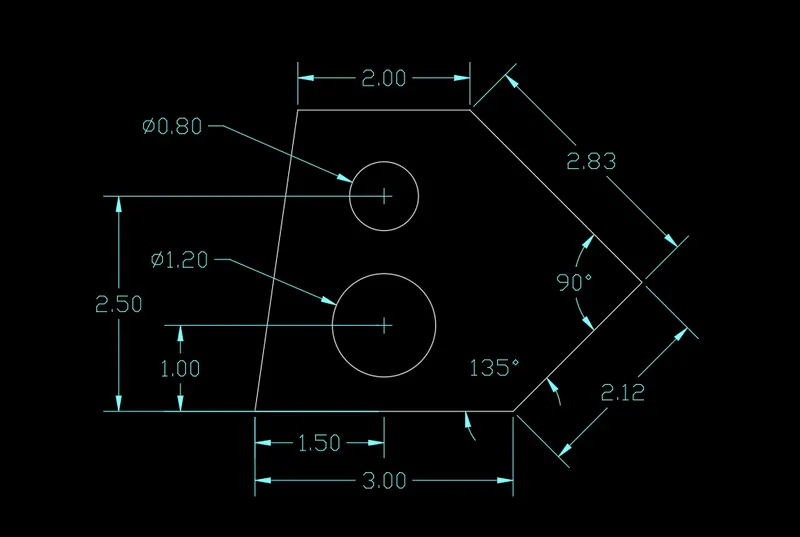
Drawing 1:
1. Open a new file and set the units as decimal and precision to 0.00.
2. Select Line tool and draw from a random point of 3 units line and (@2.12<45) (@2.83<135) then 2 units line and close.
3. Draw the first circle at (x=1, y=1) of diameter 1.2s.
4. Draw another circle at (x=1.50, y=2.50) of diameter 0.8 units.
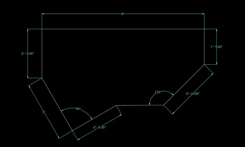
Drawing 2:
1. Set the units as Engineering and precision as 0.00.
2. Select the Line tool and draw a line of 8' x-axis 0, (@1'9"<270) and (@2'10" <225) and exit out of the line command.
3. Select line and draw from the starting point (@2'5" <270), (@3' <300), (@2'6" <30) and close.
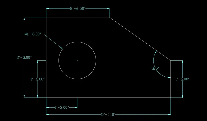
Drawing 3:
1. Set the units as Engineering and precision as 0.00.
2. Select the line tool and draw a line of (@5'0.1" <0), (@1'6.0" <90) exit out of the line command and begin the line from the starting point
3. Draw a line of (@3'3.00" <90), (@2'6.50" <0) and close.
4. From the starting point with (1'3.00", 1'6.00") draw a circle of dia 1'6.00"
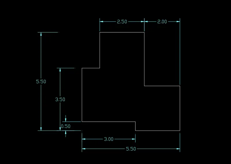
Drawing 4:
1. Set the units to Decimal.
2. Select line tool mark a random poin then (@3 <90) (@1 <0) (@2 <90) (@2.5 <0) (@3 <270) (@2 <0) (@2.5 <270) (@2.5 <180) (@0.5 <90) (@3 <180).
Drawing 5:
1. Set the units to Decimal.
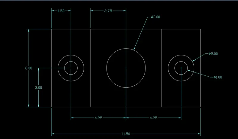
2. Select and draw a rectangle of size (@11.50, 6).
3. Using the tracking lines find the midpoint of the rectangle and draw a circle of dia 3 units
4. From the midpoint of the rectangle draw a perpendicular line of 6 units which is 2.75 units apart from the midpoint.
5. Using the mirror tool copy the line on the other side with the midpoint of the rectangle as reference.
6. Then draw two circles of dia 2 units and 1 unit from the starting point of the rectangle (1.5 x-axis and 3 y-axis)
7. Mirror the circles to the other side with the midpoint of the rectangle as reference.
Drawing 6:
1. Set the units to Decimal.
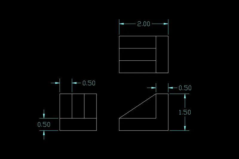
2. Select the line tool and draw lines from base units 1.5, draw offset at 0.5. Taking the total length of 1.5 draws an outer boundary and takes an offset of 0.5 for the vertical segment. Follow the steps to draw 2.0 height geometry and rotate towards the left. Using line draw the L shape geometry and close.
Drawing 7:
1. Set the units to Decimal.
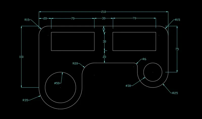
2. Draw a horizontal line of 210 units and 100 units vertical line on the left side and 75 unit vertical line on the right side.
3. From the 100 unit line extend a line of 35 units to the right and draw a circle of radius 35 units and on the other side extend a line of 25 units and draw a circle of radius 25.
4. Using the center of the circle draw a circle of dia 50 units and for the other circle 30 units.
4. Using the endpoint tracer lines from the inner circle and outer circle draw 2 lines connecting from left to right.
5. Then draw a rectangle of size (@70,30) 20 units x and 10 units y. Copy the rectangle and paste it 30 units apart.
6. Using the trim command trim the two outer circles.
7. Then using fillet command and radius sub-option give the radius as R15, R6, R20.
Drawing 8:
1. Set the units to Decimal.
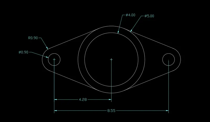
2. Draw two circles of diameter 4 and 5 units.
3. Draw another circle of dia 0.9 unit 4.275 units apart from the center of the circle.
4. From the drafting settings "DS" check the tangent and using xline and bisect join the two tangents.. and trim the ends
5. Mirror it below and trim the circle.
5. Mirror it to the other side using the center of the circle as a reference.
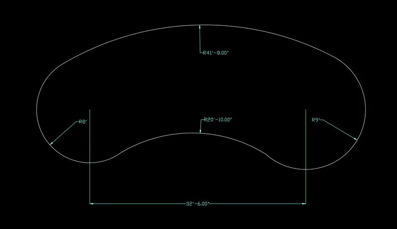
Drawing 9:
1. Set the units to Engineering.
2. Draw a line 32'6".
3. Draw a circle of radius 8' on the left side of the line and another circle of radius 9' on the right side.
4. Using arc, end, and radius draw an arc of 41'8" to the top and 20'10" on the bottom.
5. Then trim the circle and erase the line.
Drawing 10:
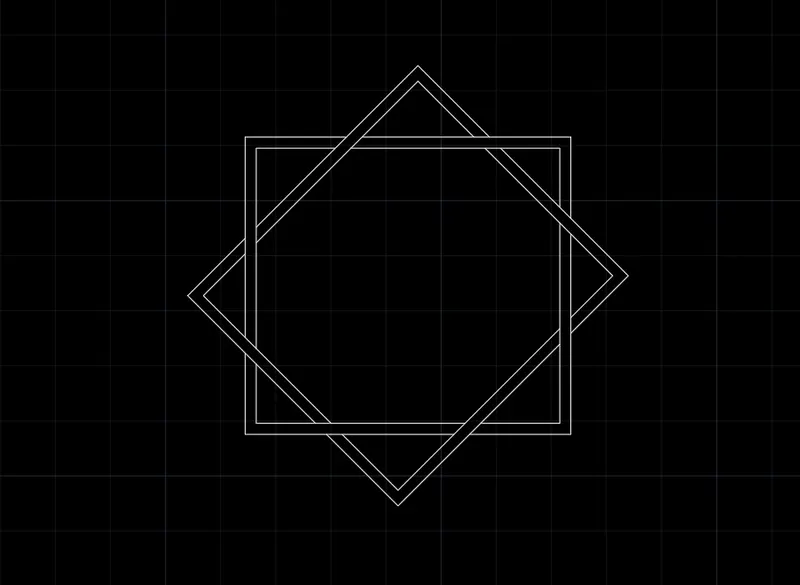
1. Set the units to Decimal.
2. Draw a square and offset it.
3. Copy and rotate it to a 45 degree and trim the other parts.
Drawing 11:
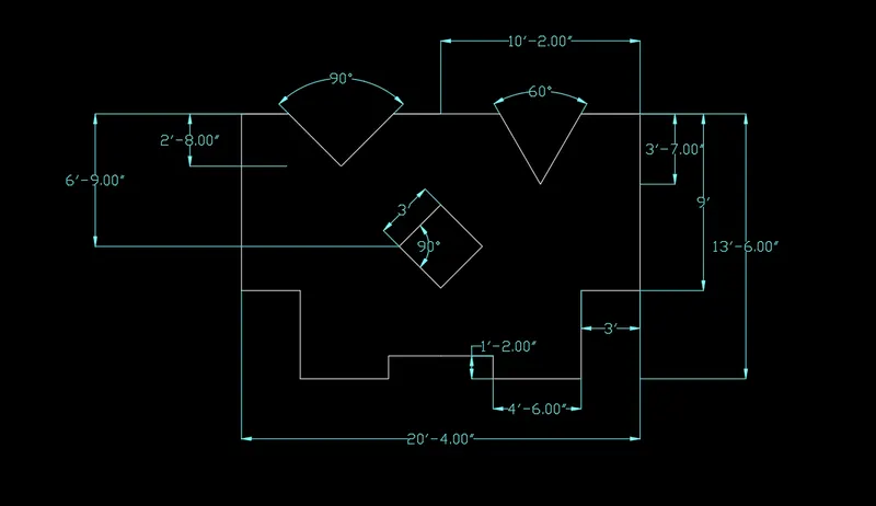
1. Set the units to Engineering.
2. Draw the line tool and draw the lengths from the top segment of 9'0", changing the position of the cursor in the direction of the line
3. Draw line of 3', 4'6", 4'6" and 1'2". close
4. Draw a square of side 3' and rotate it to 45 degrees and position it to the vertical line.
5. Draw vertical lines of 2'8" and 3'7" and make 30-degree lines on each side.
RESULT:
The given drawings are drawn using chamfer, and fillet tools in AutoCAD.