Creating a Floor plan, Footing detail and Isometric view using AutoCad
AIM:
To create a floor plan, footing detail, and isometric view using AutoCAD.
INTRODUCTION:
This assignment is to get in touch with the various tools in AutoCAD like the rectangle, polylines, modifications tools like copy, move, offset, and modes like snap mode and ortho mode.
PROCEDURE:
Tools used to sketch this drawing are,
Line ( "L" or Line on the command )
Rectangle ( "Rec" or Rectangle on the command)
Chamfer ("Cha" or Chamfer on the command )
Offset ("O" or Offset on the command )
Copy ("CO" or copy on the command )
Polyline ( "Pol" or polyline on the command)
Drafting settings ("DS" on the command )
Rotate ("RO" or rotate on the command )
Move ("M" or move on the command )
Part 1: Cross-section of load-bearing wall overspread footing.
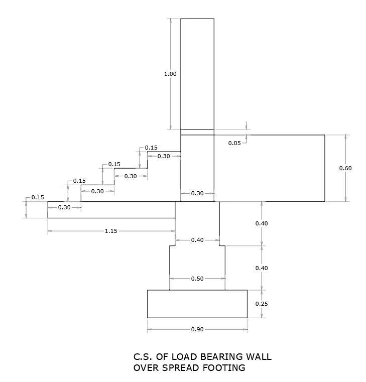
This drawing is drawn using the direct distance entry method.
First, draw a rectangle of size (@0.9,0.25)

Then the dimensions are followed from the given drawing
Basepoint is marked in Red
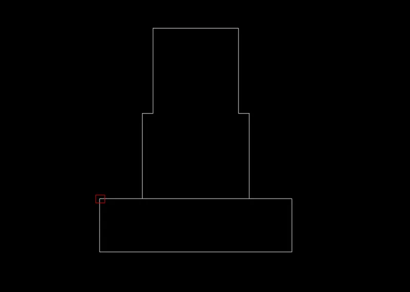
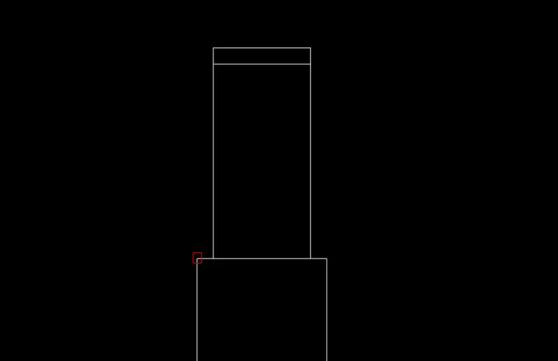
Part 2: Cross-section of load-bearing wall showing foundation details.
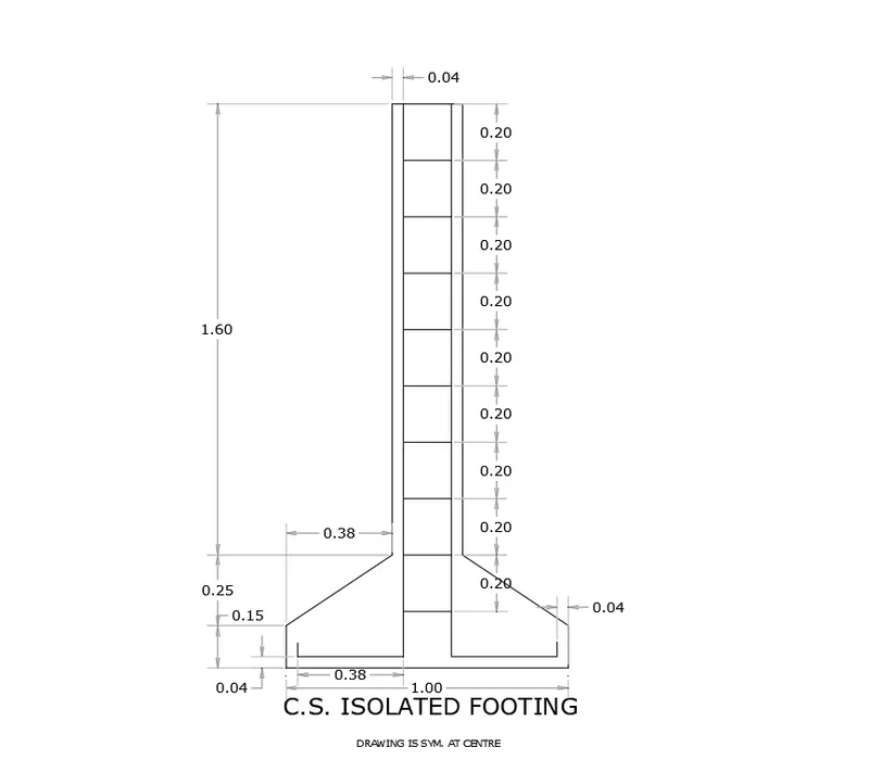
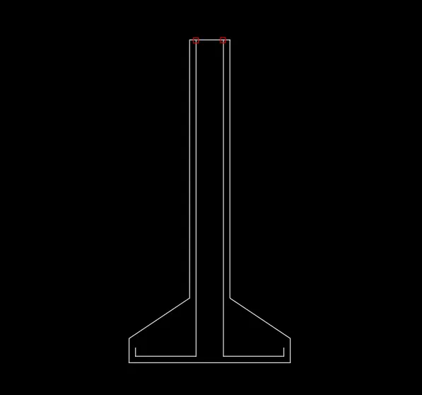
Draw a rectangle of size (@1,0.35)

Using chamfer
first distance 0.25
second distance 0.38


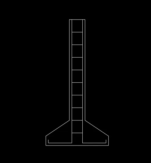
Using offset command with an offset distance of 0.2
Part 3: Line diagram of a two-bedroom building.
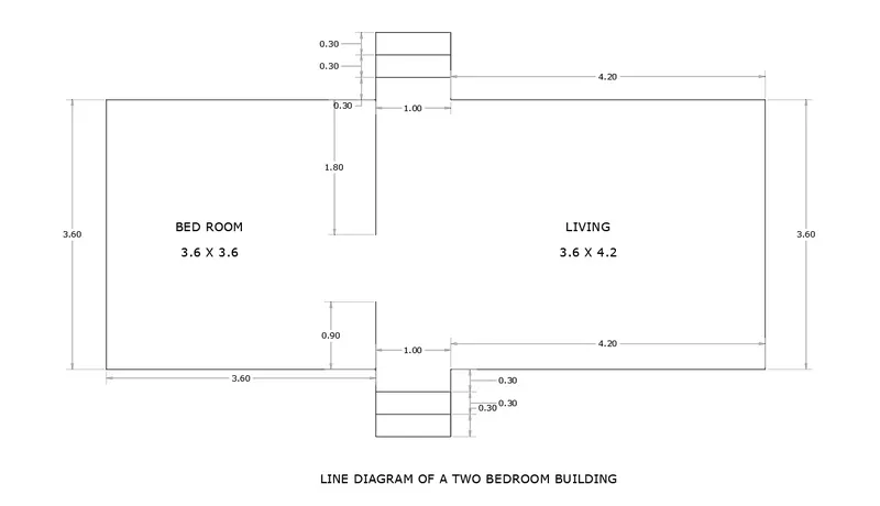
Using line specify the points (@0,1.80) (@-3.6,0) (@0,-3.6) (@3.6,0) (@1,0) (@4.20,0) (@0,3.60) (@-4.20)
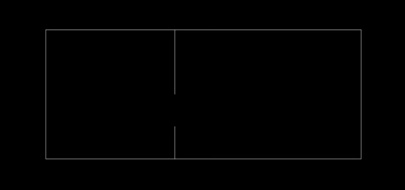
Delete the two lines

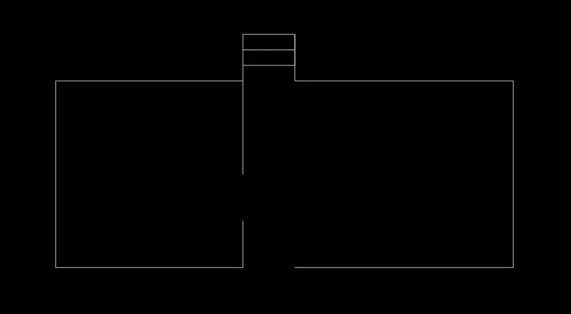
Draw the steps using the command polyline.
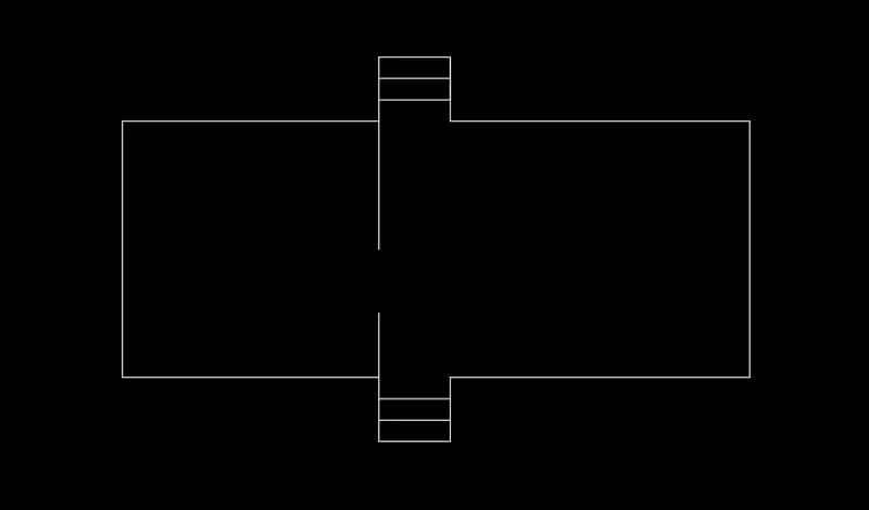
Using Rotate,copy, and Move
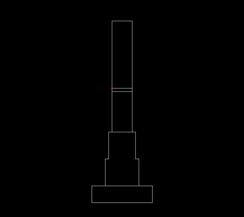
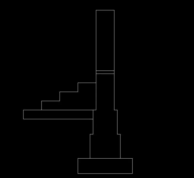
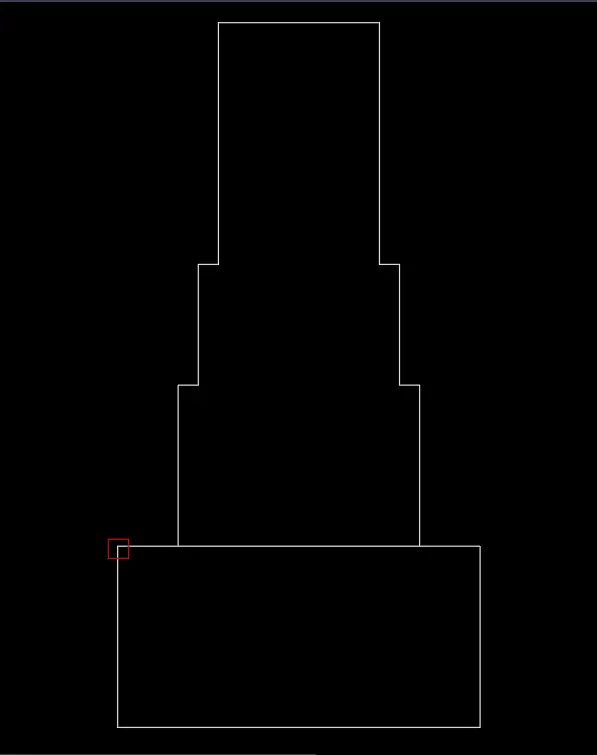
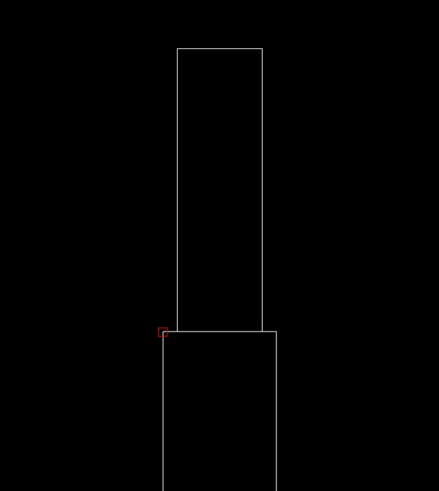
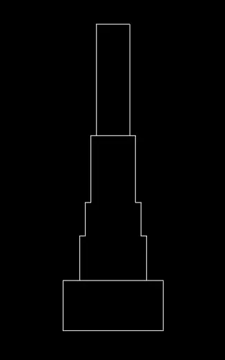
Part 4: Cross-section of load-bearing wall showing foundation details.
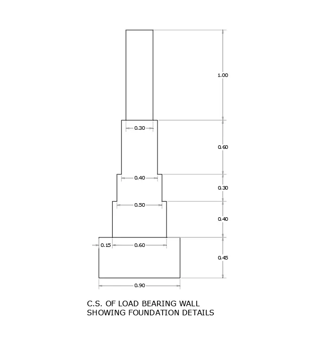
Rectangle (@.9,.45)
Line (@.15,0) (@0,0.4) (@.05,0) (@0,.3) (@.05,0) (@0,.6) (@.4,0) (@0,-0.6) (@.05,0) (@0,-0.3) (@.05,0) (@0,-0.4).
Part 5: Isometric view of steps.
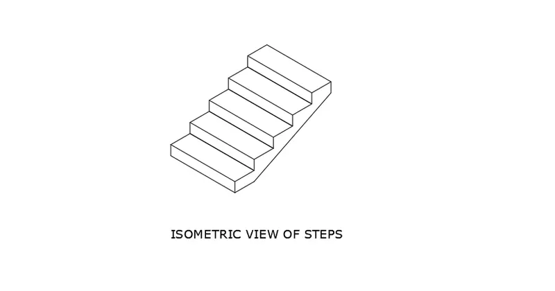
Type DS in the command line and press enter.
Unpick snap on and grid on options
Ortho should be on
Tick on isometric snap in snap type.
This will activate the isometric screen,
Type PL in the command line and press Enter.
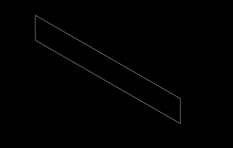
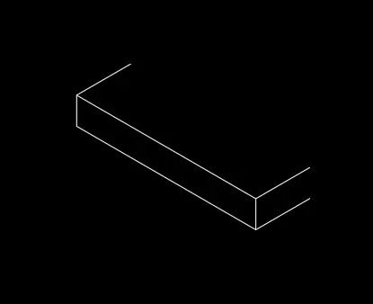
Copy the steps
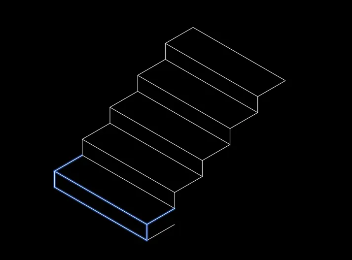
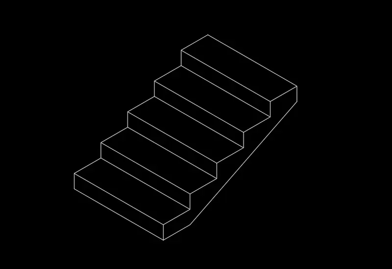
Part 6: Isometric view of Gable wall
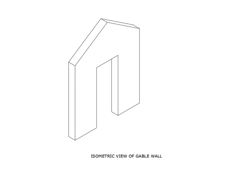
Steps are followed from part 5,


Using the midpoint of the door and the reference line we join the lines
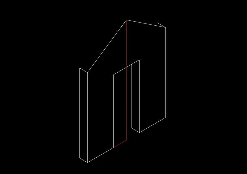
Then copy the lines using the copy command
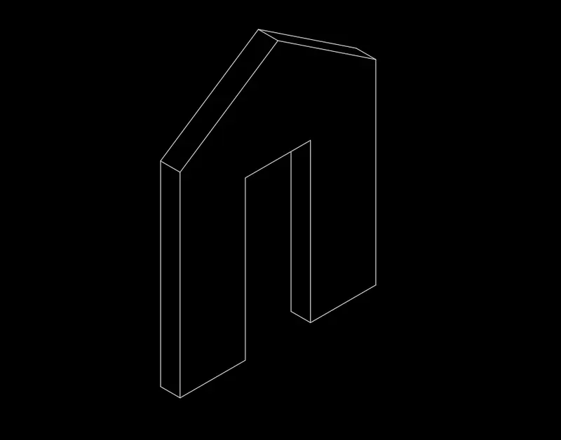
RESULTS:
Thus we created a Floor plan, Footing detail, and Isometric view using AutoCad using different commands.