Drafting of various geometries using Chamfer, Fillet tool in AutoCad
02/06/21
Answers
- FIG-1
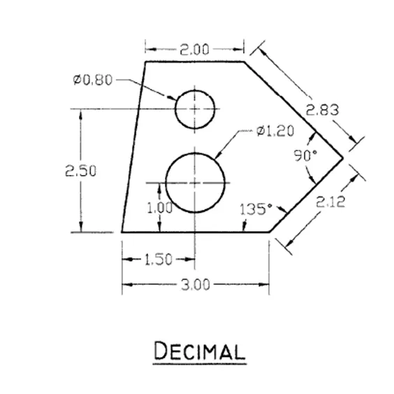
STEP-1 opening to the AutoCAD software and entering the workspace.
STEP-2 Setting limits >specify lower-left corner:0,0
STEP-3 specify upper-left corner:100,100
STEP-4 Set>units>Decimal>intersectional scale>mm
STEP-5 Limmax>100,100
STEP-6 take the line command>specify the first point:0,0
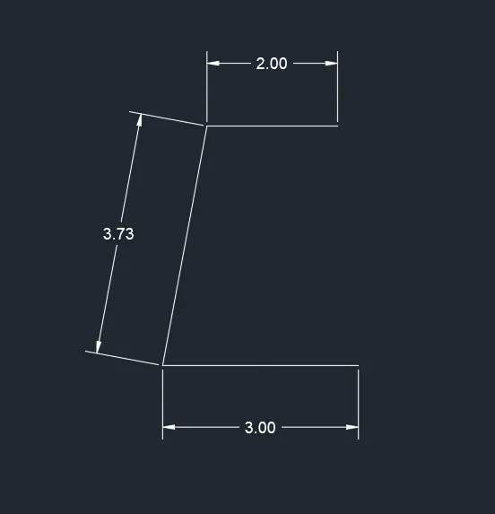
STEP-7 line command>3.00,@3.73<80,2.00
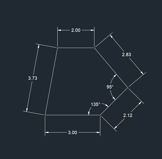
STEP-8 line command>@2.12<135°,@2.83<95
STEP-9 line command>(2.50,1.50) as center
STEP-10 make the diameter of 0.80
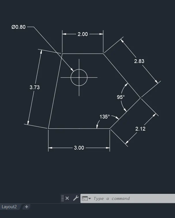
STEP-11 and close the entire object
STEP-12 and save the file for feature use.
- FIG-2
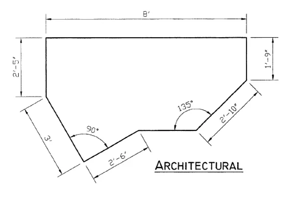
STEP-1 opens to the AutoCAD software and entering the workspace.
STEP-2 Setting limits >specify lower-left corner:0,0
STEP-3 specify upper-left corner:100,100
STEP-4 Set>units>architectural>intersectional scale>inches
STEP-5 Limmax>100,100
STEP-6 take the line command>specify the first point:0,0
STEP-7 line command>2'5'' straight line
STEP-8 line command>3' of 280° in the inclined position and 1'5'' of 90°
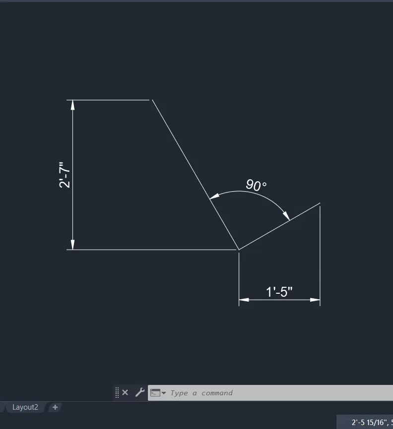
STEP-9 line command> and have a straight line and100° of 2'10'' and 90° of 1'9''
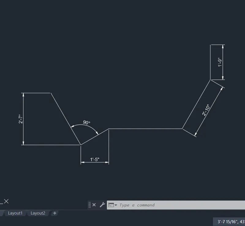
STEP-10 line command> 8' of close the object
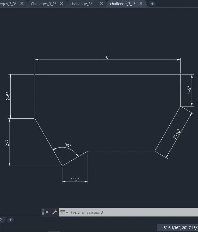
STEP-11 and save the file for feature use.
- FIG-3
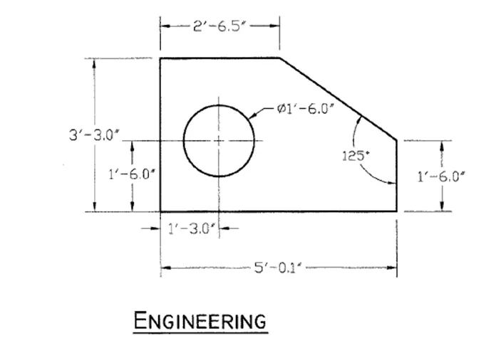
STEP-1 opens to the AutoCAD software and entering the workspace.
STEP-2 Setting limits >specify lower-left corner:0,0
STEP-3 specify upper-left corner:100,100
STEP-4 Set>units>architectural>intersectional scale>inches
STEP-5 Limmax>100,100
STEP-6 take the line command>specify the first point:0,0
STEP-7 line command>5' straight line and 90° of a straight line of 1'6''
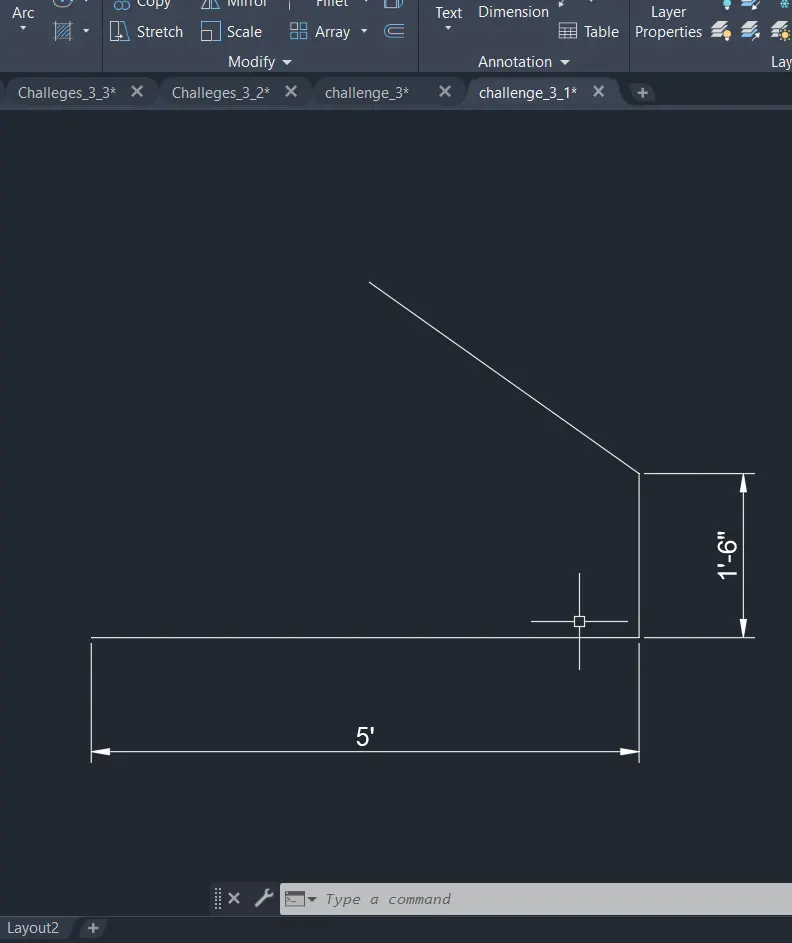
STEP-8 line command> for the starting point move in the x-axis of 2'6''
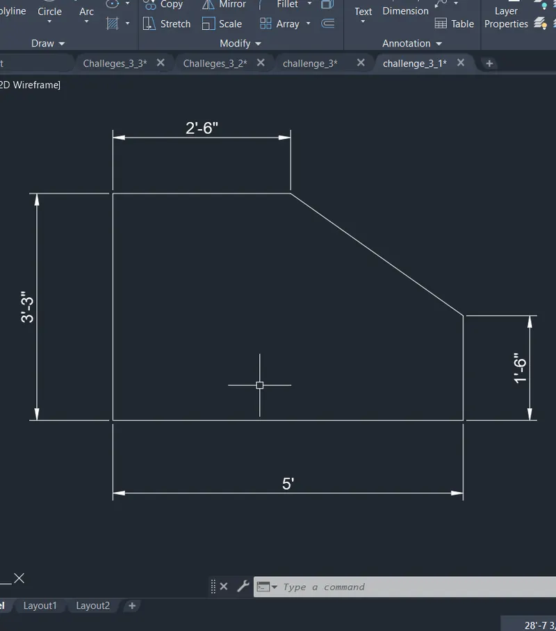
STEP-9 line command> join the entire object
STEP-10 1'6'' and 1'3'' as center draw the circle
STEP-11 and mark the diameter as 1'6''
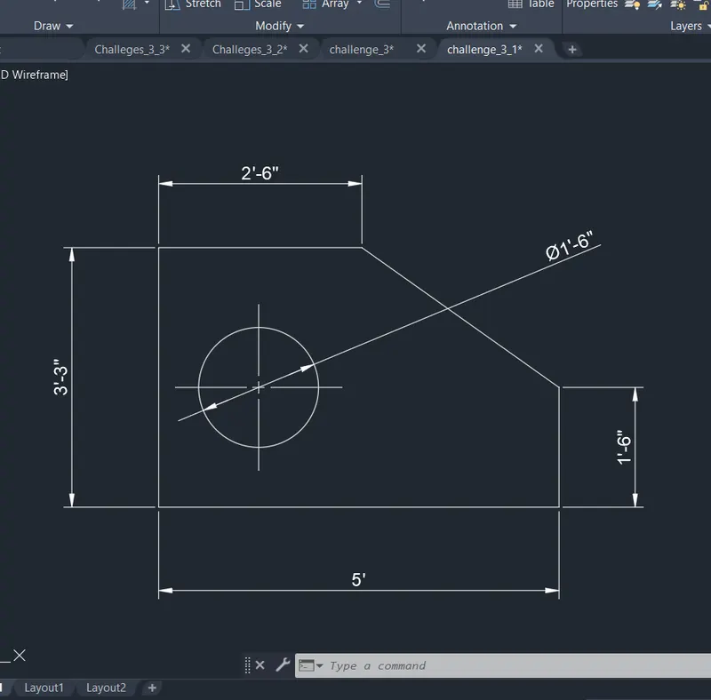
STEP-12 and save the file for feature use.
- FIG-4
STEP-1 opens to the AutoCAD software and entering the workspace.
STEP-2 Setting limits >specify lower-left corner:0,0
STEP-3 specify upper-left corner:100,100
STEP-4 Set>units>decimal>intersectional scale>mm
STEP-5 Limmax>100,100
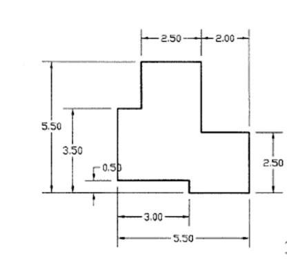
STEP-6 take the line command>specify the first point:0,0
STEP-7 line command>5.50 make the straight line in the X-axis
STEP-8 line command> for the starting point move in the Y-axis of 5.50
STEP-9 line command>5.50 make the straight line in the X-axis
STEP-10 line command> for the starting point move in the Y-axis of 5.50.
STEP-11 offset command> 3 in the X-axis and 2 in the Y-axis.
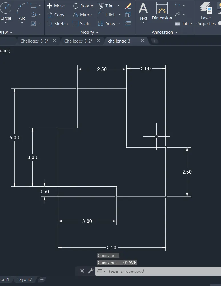
STEP-12 and mark the line command to close the object.
STEP-13 and save the file for feature use.
- FIG-5
STEP-1 opens to the AutoCAD software and entering the workspace.
STEP-2 Setting limits >specify lower-left corner:0,0
STEP-3 specify upper-left corner:100,100
STEP-4 Set>units>decimal>intersectional scale>mm
STEP-5 Limmax>100,100
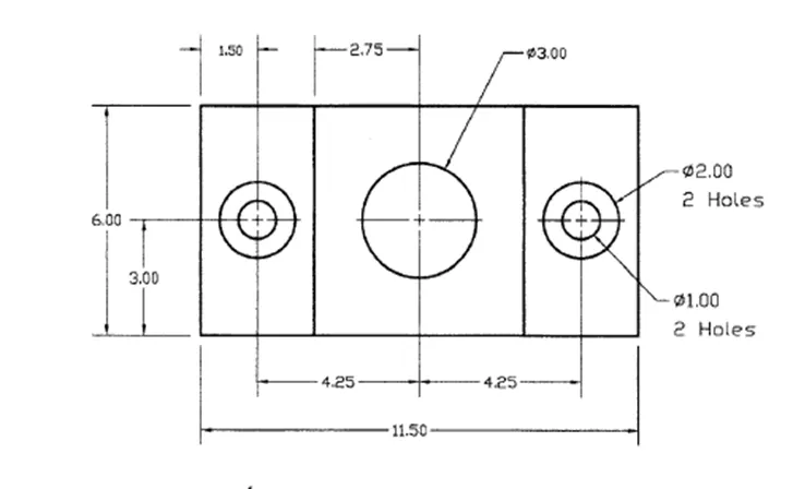
STEP-6 take the line command>specify the first point:0,0
STEP-7 line command>6mm in the X-axis and 11.50mm in the Y-axis and close the entire object.
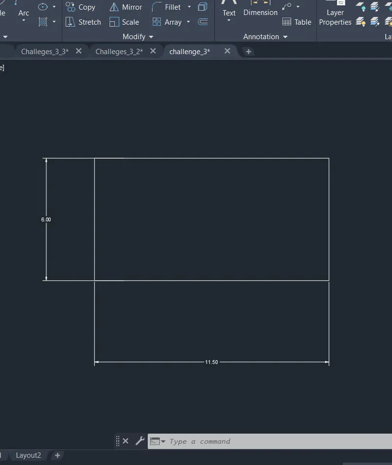
STEP-8 Offset command> for the starting point move in the Y-axis of 1.50 and moving in the X-axis 3 make the circle
STEP-9 circle command>diameter of 2mm and 1mm make the circle
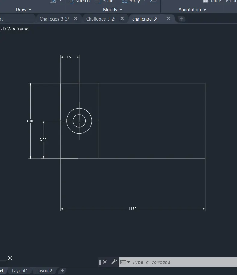
STEP-10 Offset command> for the starting point move in the Y-axis of 4.25mm and moving in the X-axis 3 make the circle as the center.
STEP-11 circle command>diameter of 3mm.
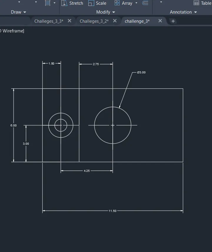
STEP-12 Offset command> for the starting point move in the Y-axis of 4.25mm and moving in the X-axis 3 make the circle as the center.
STEP-13 circle command>diameter of 2mm and 1mm make the circle.
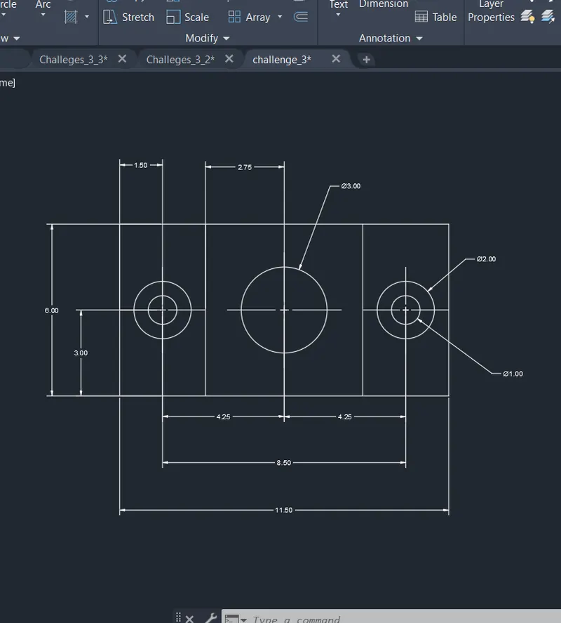
STEP-14 and save the file for feature use.
- FIG-6
STEP-1 opens to the AutoCAD software and entering the workspace.
STEP-2 Setting limits >specify lower-left corner:0,0
STEP-3 specify upper-left corner:100,100
STEP-4 Set>units>decimal>intersectional scale>mm
STEP-5 Limmax>100,100
STEP-6 take the line command>specify the first point:0,0
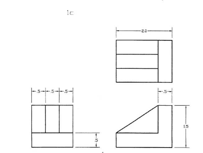
STEP-7 line command>1.50mm in the X-axis and 1.50mm in the Y-axis and close the entire object.
STEP-8 Offset command> for the starting point move in the Y-axis of 0.50 and moving in the X-axis.
STEP-9 makes 3 pairs of lines on the Y-axis and 1 pair on the X-axis.
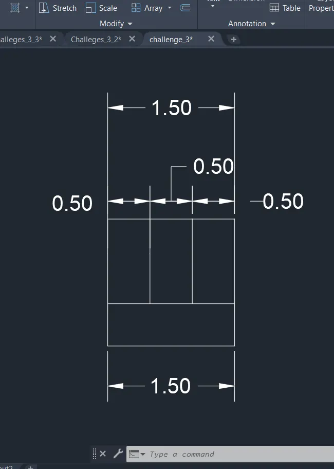
STEP-10 line command>2mm in the X-axis and 1.50mm in the Y-axis
STEP-11 line command> break of 0.50mm and join diagonally
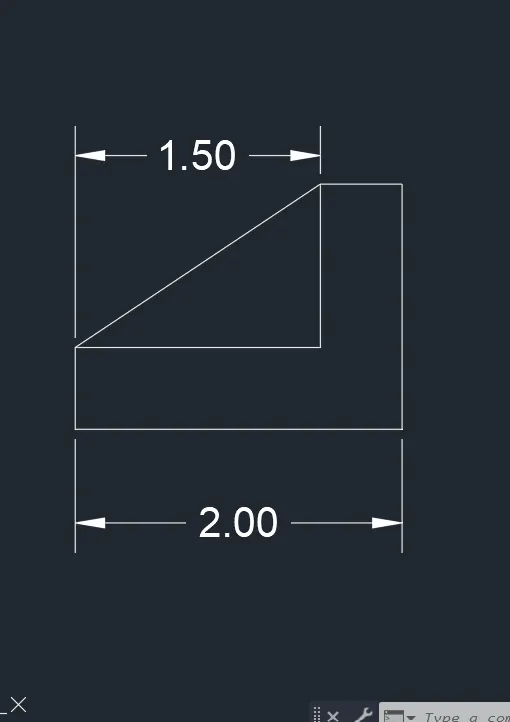
STEP-12 line command>1.50mm in the X-axis and 1.50mm in the Y-axis and close the entire object.
STEP-13Offset command> for the starting point move in the Y-axis of 0.50 and moving in the X-axis.
STEP-14 makes 3 pairs of lines on the Y-axis and 1 pair on the X-axis.
STEP-15 ROTATE command>tilt 90°
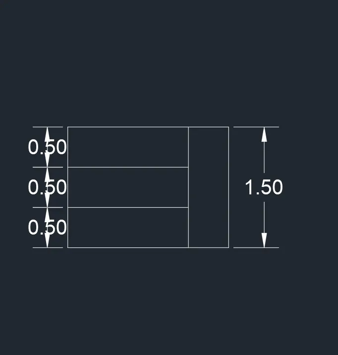
STEP-16 and save the file for feature use.
- FIG-7
STEP-1 opens to the AutoCAD software and entering the workspace.
STEP-2 Setting limits >specify lower-left corner:0,0
STEP-3 specify upper-left corner:100,100
STEP-4 Set>units>decimal>intersectional scale>mm
STEP-5 Limmax>100,100
STEP-6 take the line command>specify the first point:0,0
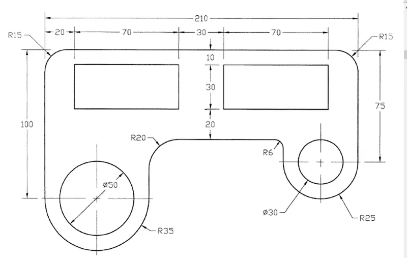
STEP-7 line command>210mm in the X-axis and 100mm in the Y-axis and another side 75mm on Y-axis
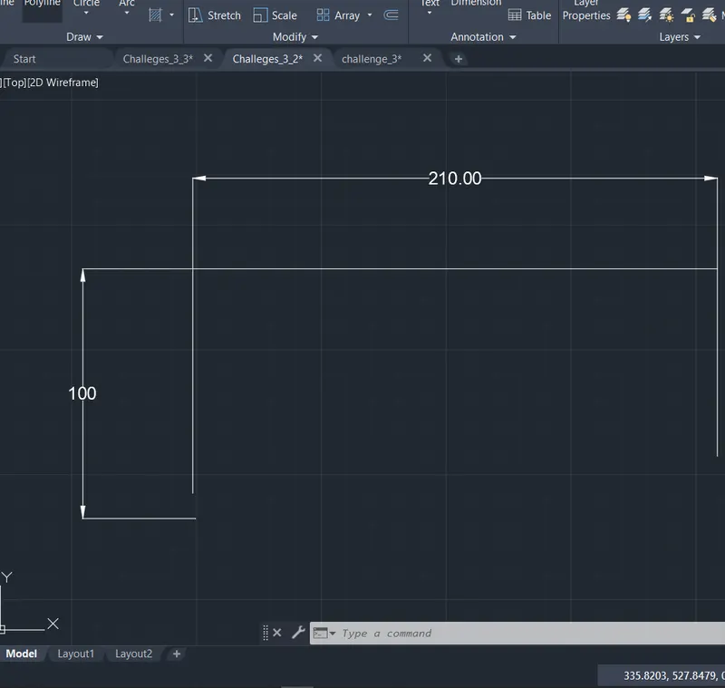
STEP-8 2point circle command> in the 100mm side and the radius of 35mm and 75mm side and its radius of 25mm
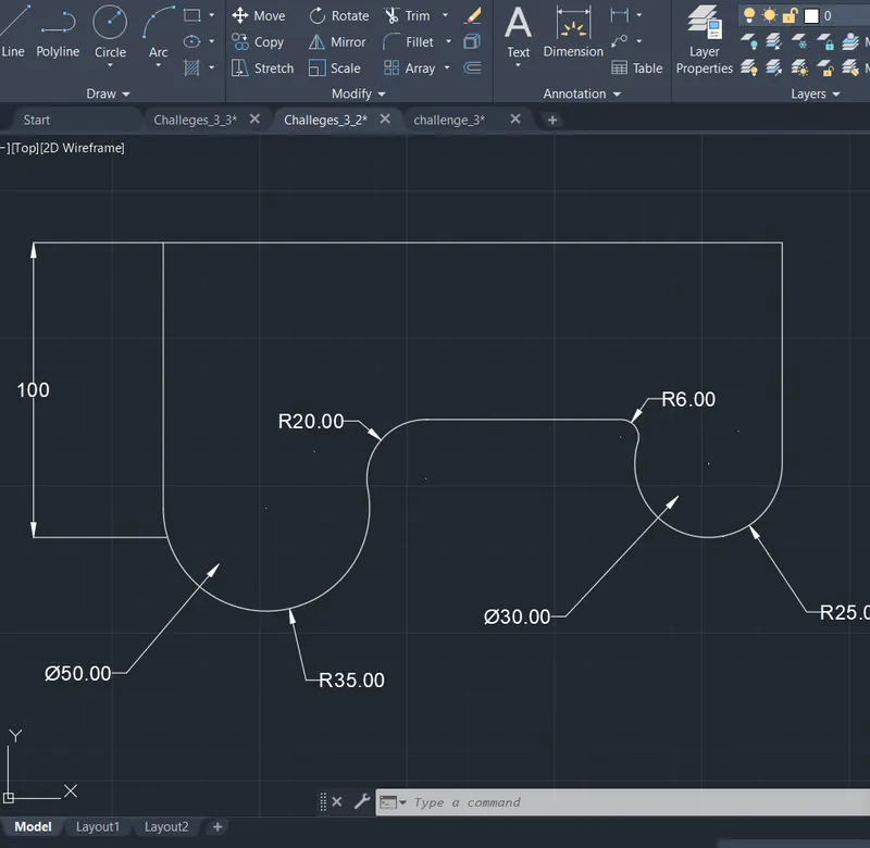
STEP-9 center marks command> mark the center.
STEP-10 mark as the center, circle command> 30 dia and 50 dia in both sides.
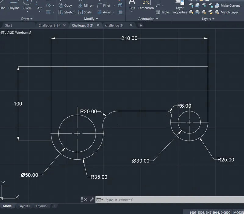
STEP-11 offset command> make the marking as 20,70,30,70,20 in the X-axis.
STEP-12 offset command> make the marking as 10,30 20 in the Y-axis.
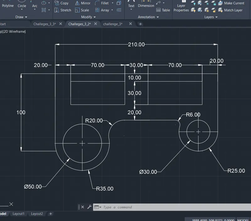
STEP-13 Trim command> remove the unwanted line and make it as good.
STEP-14 and save the file for feature use.
- FIG-8
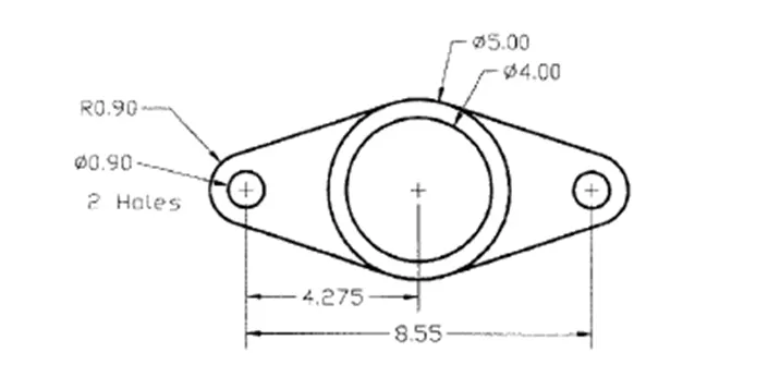
STEP-1 opens to the AutoCAD software and entering the workspace.
STEP-2 Setting limits >specify lower-left corner:0,0
STEP-3 specify upper-left corner:100,100
STEP-4 Set>units>decimal>intersectional scale>mm
STEP-5 Limmax>100,100
STEP-6 take the line command>specify the first point:0,0
STEP-7 line command>draw a line of 8.55mm
STEP-8 circle command>dia of 0.90 draws on the two ends of the line.
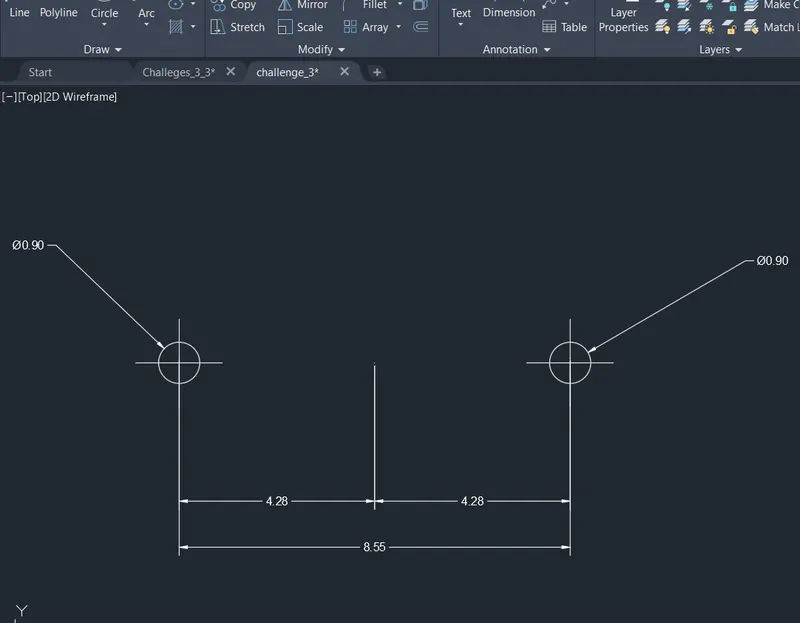
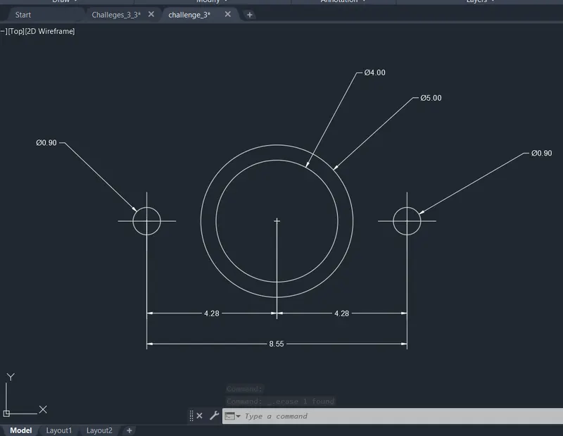
STEP-9 line command>4.28mm in the X-axis and make the two circles
STEP-10 Circle command>dia of 4mm and 5mm in the same point
STEP-11 Circle command> radius 0.9mm on the small circle on both sides.
STEP-12 line command>shift + right-click (tangent line)of the circle 1 to circle 2 on both sides
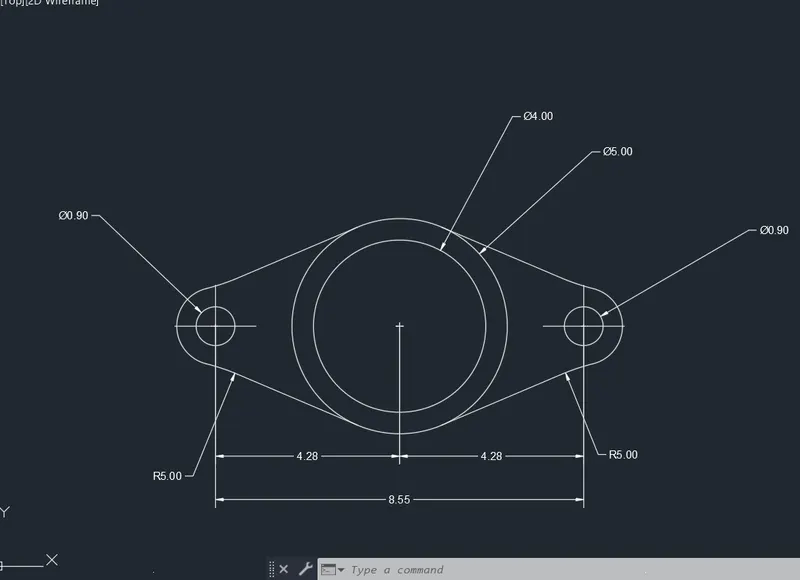
STEP-13 trim command> all unwanted line are removed
STEP-14 and save the file for feature use.
- FIG-9
STEP-1 opens to the AutoCAD software and entering the workspace.
STEP-2 Setting limits >specify lower-left corner:0,0
STEP-3 specify upper-left corner:100,100
STEP-4 Set>units>decimal>intersectional scale>mm
STEP-5 Limmax>100,100
STEP-6 take the line command>specify the first point:0,0
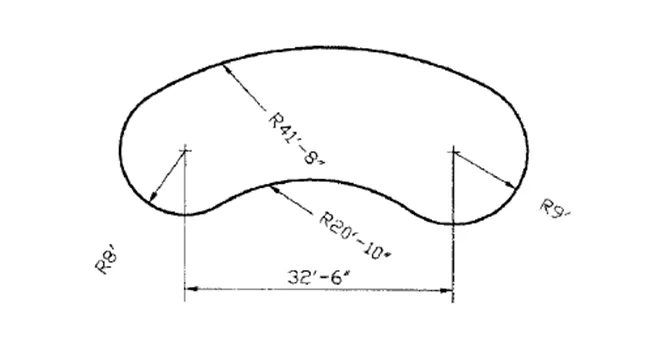
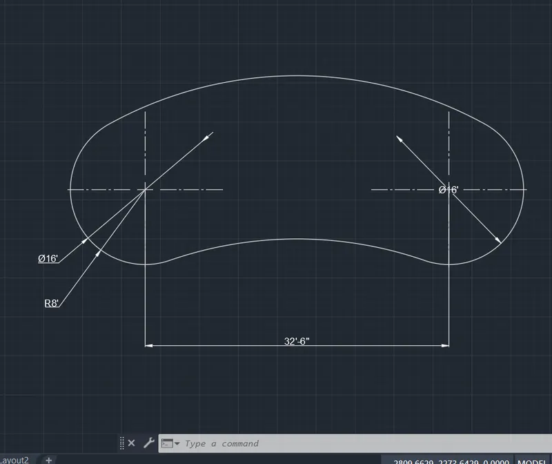
STEP-7 circle command>radius of 8' and radius of 9'
STEP-8 line command>in between distance of 32'4''
STEP-9 Circle command>tan, tan, radius command is used and make the circle of Radius 41'8'' in top
STEP-10 Circle command>tan, tan, radius command is used and make the circle of Radius 41'8'' in downside
STEP-11 Trim command>remove the unwanted line.
STEP-12 and save the file for feature use.
- FIG-10
STEP-1 opens to the AutoCAD software and entering the workspace.
STEP-2 Setting limits >specify lower-left corner:0,0
STEP-3 specify upper-left corner:100,100
STEP-4 Set>units>decimal>intersectional scale>mm
STEP-5 Limmax>100,100
STEP-6 take the line command>specify the first point:0,0
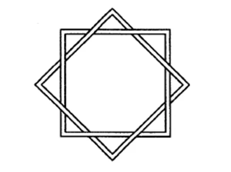
STEP-7 line command>11mm in the X-axis and Y-axis and close the object.
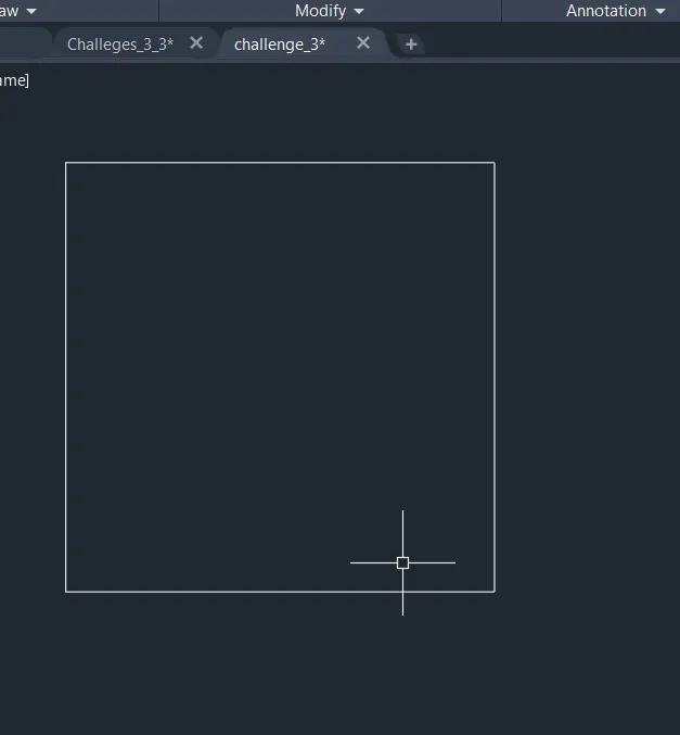
STEP-8 offset command> 0.50mm in the X-axis and Y-axis and close the object.
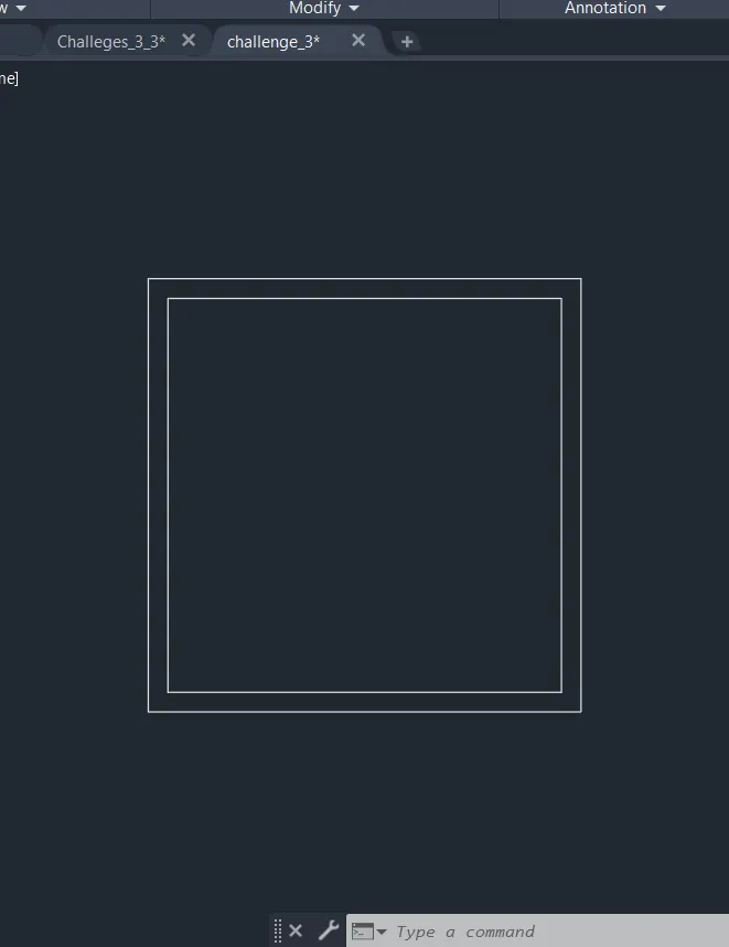
STEP-9 offset command >1mm as offset and make the imaginary line.
STEP-10 start doing in diagonal form.
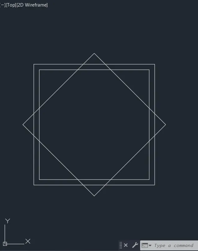
STEP-11 offset command> 0.50mm in the X-axis and Y-axis and close the object.
STEP-12 offset command >1mm as offset and make the imaginary line.
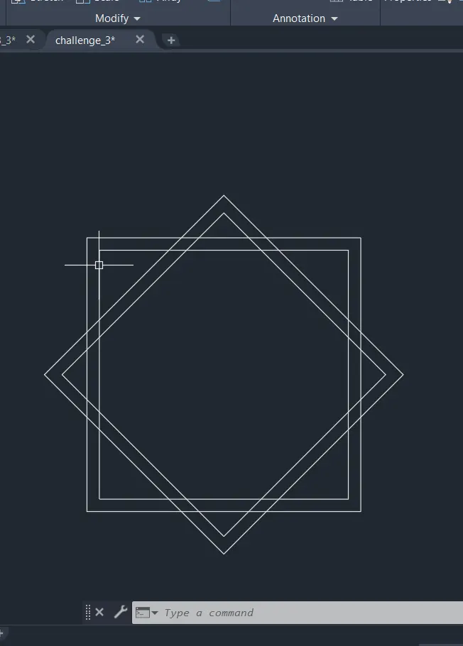
STEP-13 and save the file for feature use.
- FIG-11
STEP-1 opens to the AutoCAD software and entering the workspace.
STEP-2 Setting limits >specify lower-left corner:0,0
STEP-3 specify upper-left corner:100,100
STEP-4 Set>units>architectural>intersectional scale>inche
STEP-5 Limmax>100,100
STEP-6 take the line command>specify the first point:0,0
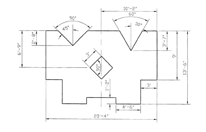
STEP-7 line command>13'6''inches in the Y-axis 20'4'' in the X-axis and close the entire object.
STEP-8 Offset command> 3',4'6'',5'4'',7'6'',3' moves in the X-axis
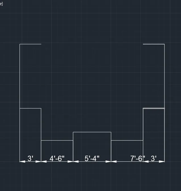
STEP-9 Offset command> 4'6'',9'2'8'' move in the Y-axis
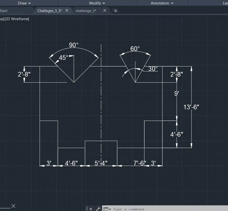
STEP-10 trim command> remove the unwanted lines
STEP-10 in the 2'8'' mark, we want to make the 45° and 30° angle
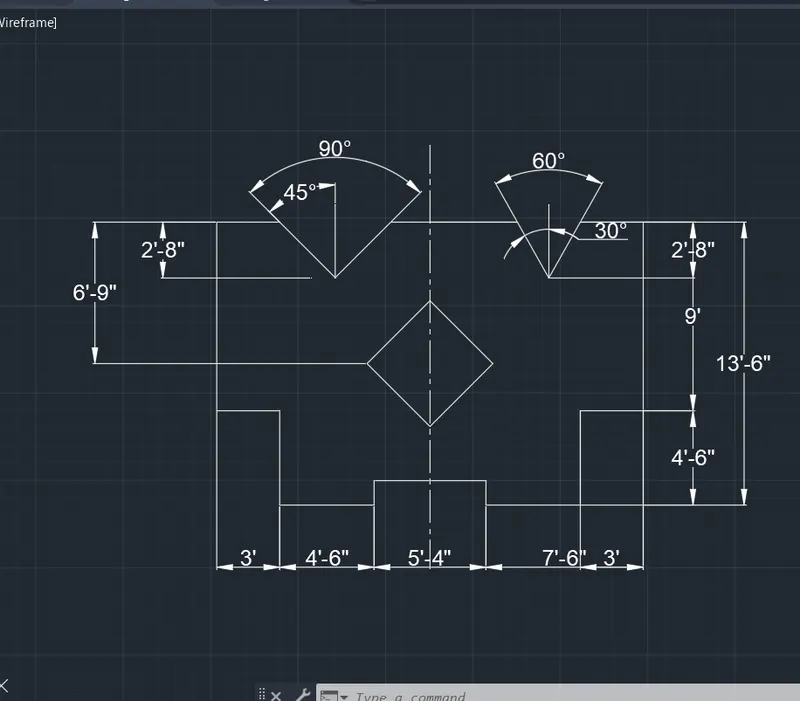
STEP-11 Offset command> 6'9'' and 10'2'' as center make the mark
STEP-12 line command>3' diagonally make the square shape.
STEP-13 makes the central line in the middle of the object.
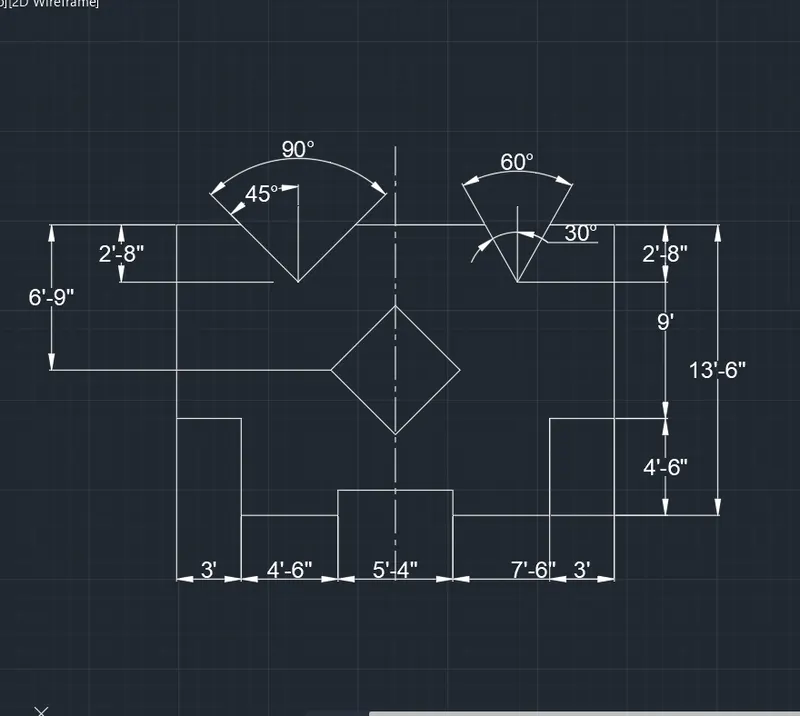
STEP-14 and save the file for feature use.
_______________________________________________________________________________________________________________________________________________________