Creating a Floor plan, Footing detail and Isometric view using AutoCad
30/05/21
ANSWERS
C1- C.S. OF LOAD-BEARING WALL OVER SPREAD FOOTING
STEP-1 opening to the AutoCAD software and entering the workspace.
STEP-2 Setting limits >specify lower-left corner:0,0
STEP-3 specify upper-left corner:100,100
STEP-4 Set>units>Decimal>intersectional scale>mm
STEP-5 Limmax>100,100
STEP-6 take the line command>specify the first point:0,0
STEP-7 first step we are making the footing
STEP-8 while taking the line command>specify the second point:0.90,0.25,0.20,0.40,0.05,
0.40,0.05,0.30,0.05,0.40,0.05,0.40,0.20,0.25
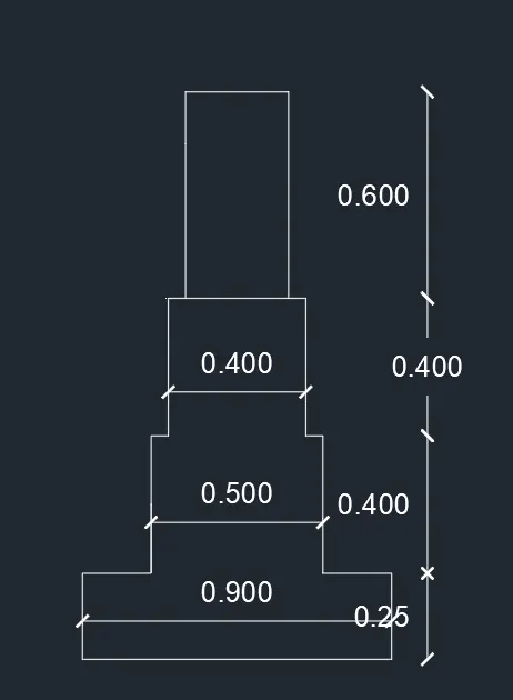
STEP-9 in the step we are creating the ground level and the stair
STEP-10 the length of the first thread was 1.15 and the rise was 0.30
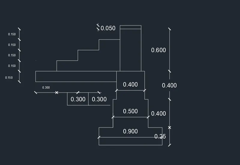
STEP-11 take the line command>specify the first point: select the desired area
STEP-12 while taking the line command>specify the second
point:0.90,0.25,0.20,0.40,0.05,0.40,0.05,0.30,0.05,0.40,0.05,0.40,0.20,0.25
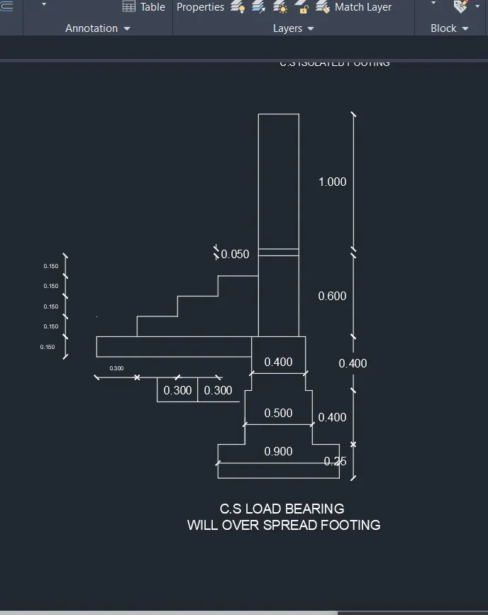
STEP-13 third step we raising the wall for 1.00
STEP-14 take the line command>specify the first point: select the desired area
STEP-15 while taking the line command>specify the second
point:1.00,0.30,1.00
STEP-16 and close the entire object
STEP-17 and save the file for feature use.
C2-C.S. ISOLATED FOOTING
STEP-1 opening to the AutoCAD software and entering the workspace.
STEP-2 Setting limits >specify lower-left corner:0,0
STEP-3 specify upper-left corner:100,100
STEP-4 Set>units>Decimal>intersectional scale>mm
STEP-5 Limmax>100,100
STEP-6 take the line command>specify the first point:0,0
STEP-7 first step we are making the isolated footing
STEP-8 while taking the line command>specify the second point:0.15,1.00,0.15
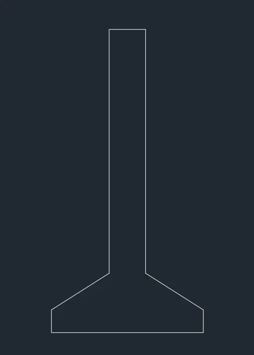
STEP-9 taking the offset>0.38 both the side A and B
STEP-10 take the line command>specify the first point: select the desired area
STEP-11while taking the line command>specify the second
point:2.00 for the straight line on both side C to D and E to F
STEP-12 taking the offset>0.04 both the side C to D and E to F
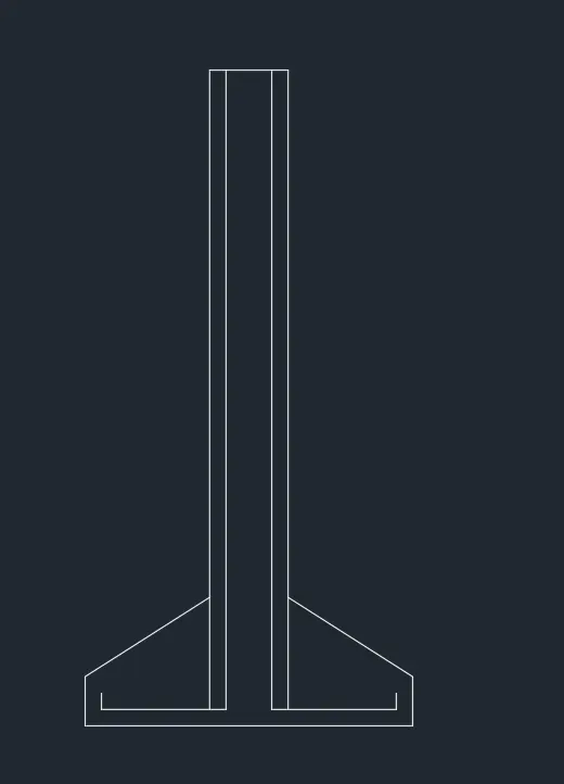
STEP-13 taking the offset>0.2 on top to bottom
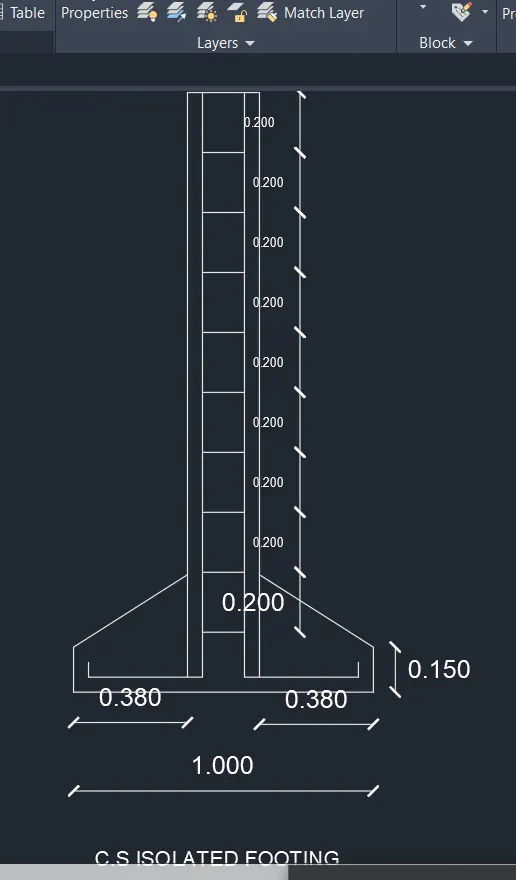
STEP-14 and close the entire object
STEP-15 and save the file for feature use.
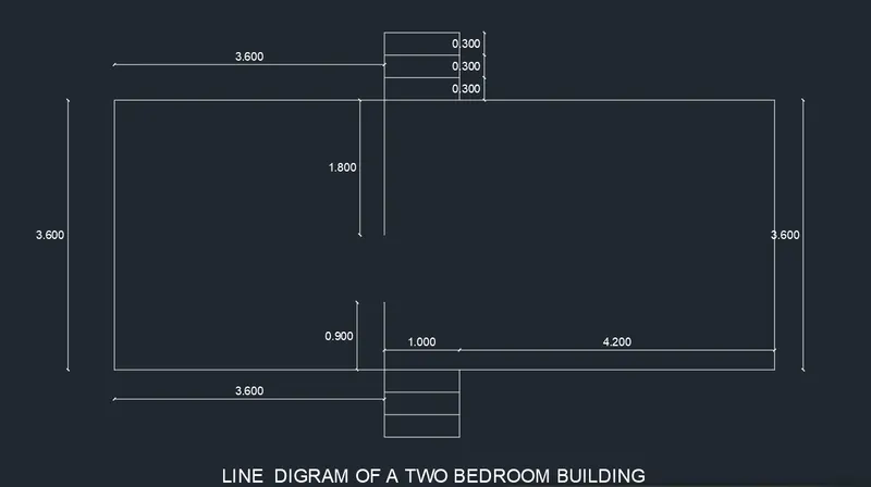
C3-LINE DIAGRAM OF A TWO-BEDROOM BUILDING
STEP-1 opening to the AutoCAD software and entering the workspace.
STEP-2 Setting limits >specify lower-left corner:0,0
STEP-3 specify upper-left corner:100,100
STEP-4 Set>units>Decimal>intersectional scale>mm
STEP-5 Limmax>100,100
STEP-6 take the line command>specify the first point:0,0
STEP-7 first step we are making the outer boundary
STEP-8 while taking the line command>specify the second point:8.8,3.60,8.80,3.60
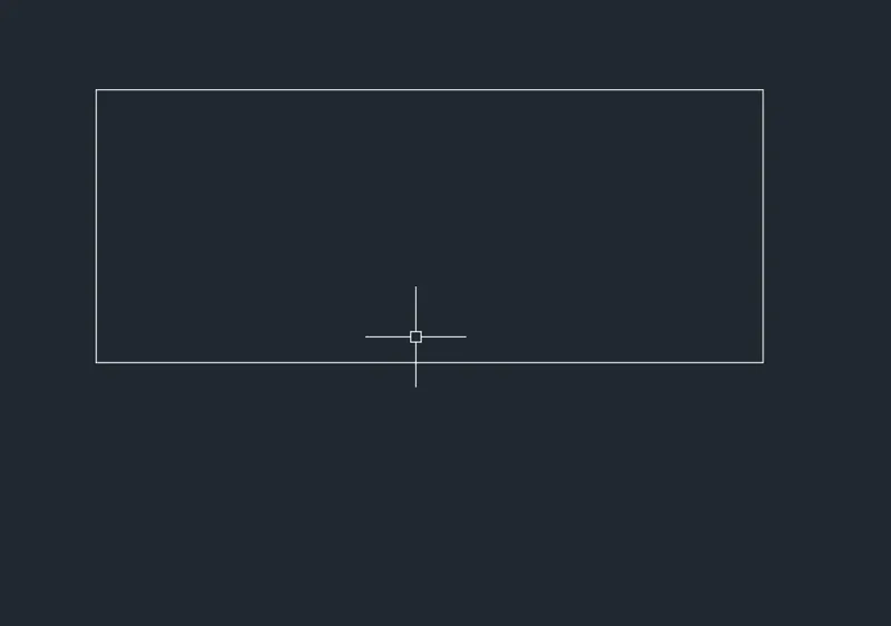
STEP-9 partition of the bedroom and living and two sides stair
STEP-10 considers the bedroom as 3.6x3.6 and living 3.6x4.2
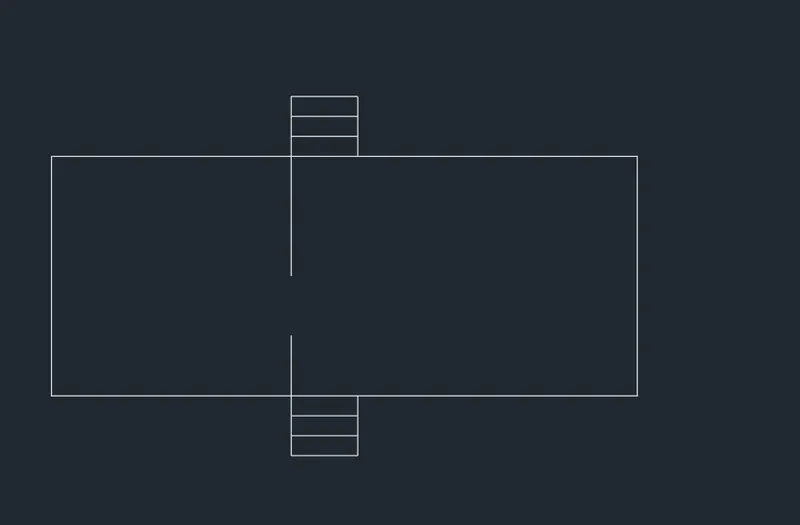
STEP-11 and there has a two sidestep of 0.30
STEP-12 dimensional arrangement of the plan
STEP-13 using the DIMLIN>COMMAND for the following area
STEP-14 and close the entire object
STEP-15 and save the file for feature use.
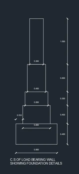
C4-C.S. OF LOAD-BEARING WALL SHOWING FOUNDATION DETAILS
STEP-1 opening to the AutoCAD software and entering the workspace.
STEP-2 Setting limits >specify lower-left corner:0,0
STEP-3 specify upper-left corner:100,100
STEP-4 Set>units>Decimal>intersectional scale>mm
STEP-5 Limmax>100,100
STEP-6 take the line command>specify the first point:0,0
STEP-7 first step we are making the outer boundary
STEP-8 specify the second point on the desire area
STEP-9 while taking the line command>specify the second point:0.90,0.45,0.150.40,0.05,0.30,0.05,0.60,0.05,1.0,0.30,1.0,0.05,0.60,0.05,0.30,0.05,0.40,0.15,0.45
STEP-10 and close the entire object
STEP-11and save the file for feature use.
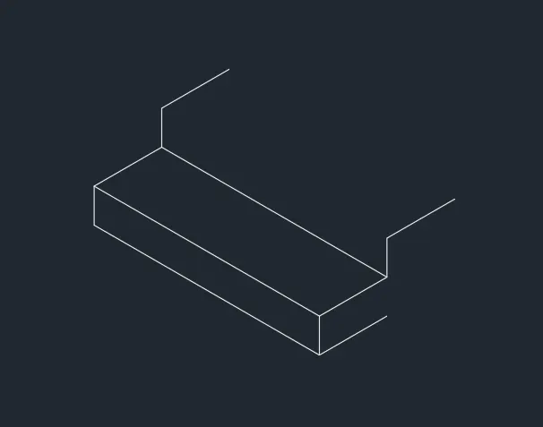
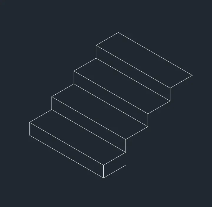
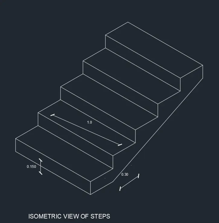
C5-ISOMETRIC VIEW OF STEPS
STEP-1 opening to the AutoCAD software and entering the workspace.
STEP-2 Setting limits >specify lower-left corner:0,0
STEP-3 specify upper-left corner:100,100
STEP-4 Set>units>Decimal>intersectional scale>mm
STEP-5 Limmax>100,100
STEP-6 take the line command>specify the first point:0,0
STEP-7 first step we are making the Isometric view of steps
STEP-8 make the isometric option active
STEP-9 toggle between the isometric right, left,top
STEP-10 while taking the line command>specify the second point,1.0,0.15,1.0,0.15,0.30,1.0,0.30,1.0,0.15,1.0,0.15,0.30,1.0,0.30,
STEP-11 take the line command>specify the first point: make the point on the desired area
STEP-12 while taking the line command>specify the second point,1.0,0.15,1.0,0.15,0.30,1.0,0.30,1.0,0.15,1.0,0.15,0.30,1.0,0.30,
STEP-13 and close the entire object
STEP-14 and save the file for feature use.
C6-ISOMETRIC VIEW OF GABLE WALL
STEP-1 opening to the AutoCAD software and entering the workspace.
STEP-2 Setting limits >specify lower-left corner:0,0
STEP-3 specify upper-left corner:100,100
STEP-4 Set>units>Decimal>intersectional scale>mm
STEP-5 Limmax>100,100
STEP-6 take the line command>specify the first point:0,0
STEP-7 first step we are making the ISOMETRIC VIEW
STEP-8 while taking the line command>specify the second point:1.0,2.42,1.0,2.42,1.0
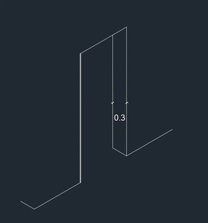
STEP-9 take the line command>specify the first point: make the point on the desired area
STEP-10 while taking the line command>specify the second point,3.0,0.3,3
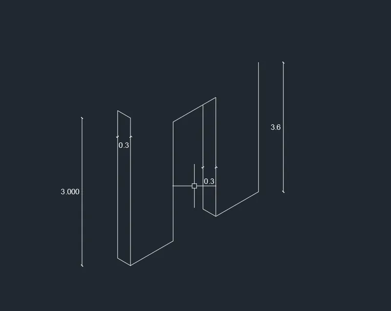
STEP-11 take the line command>specify the first point: select the desired area
STEP-12while taking the line command>specify the second,0.25,@1.25<60,0.25,2.0
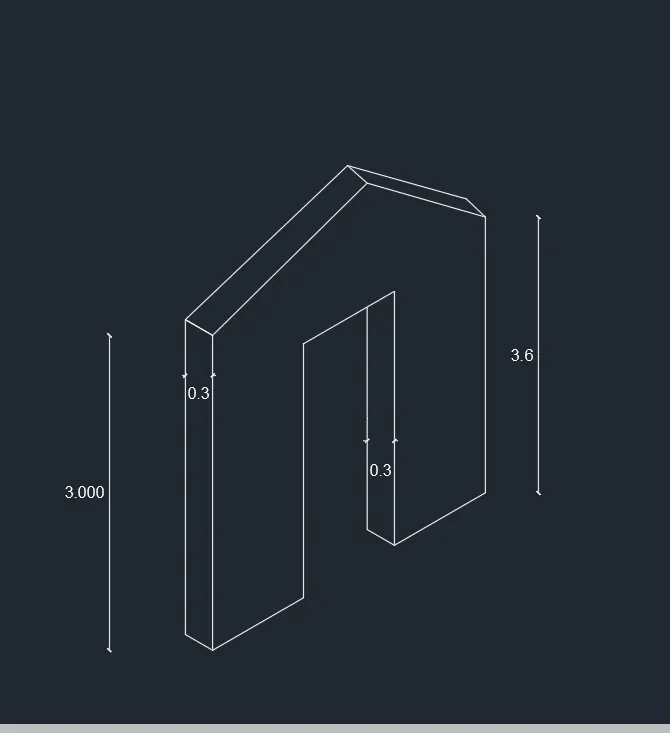
STEP-13 and close the entire object
STEP-14 and save the file for feature use.