Drafting of various geometries using Chamfer, Fillet tool in AutoCad
Q) Draw the following figures in detail using AutoCAD software.
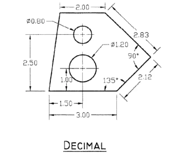
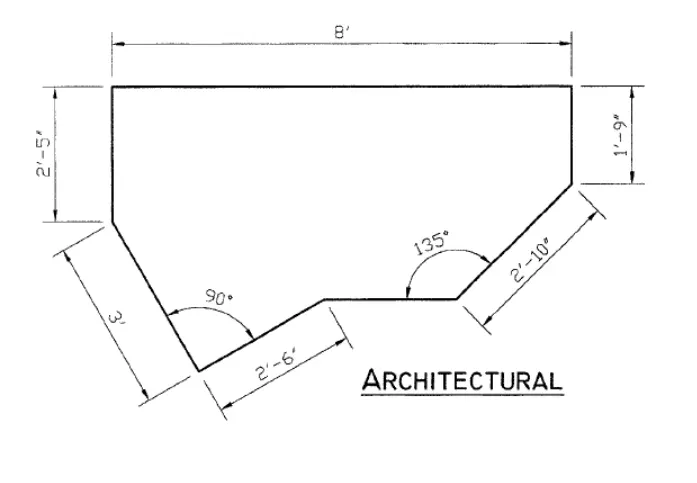
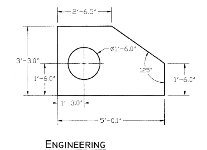
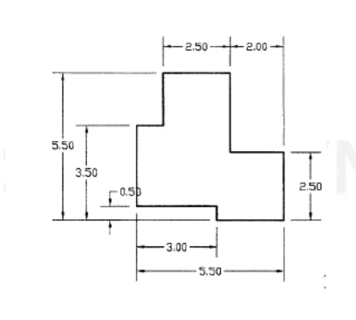
Figure -1 Figure - 2 Figure - 3 Figure - 4
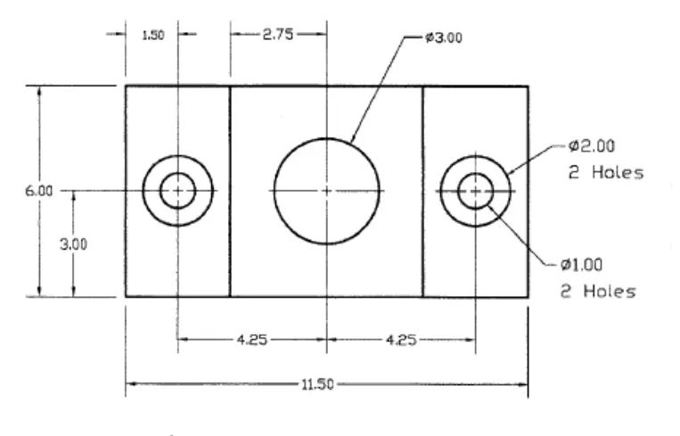
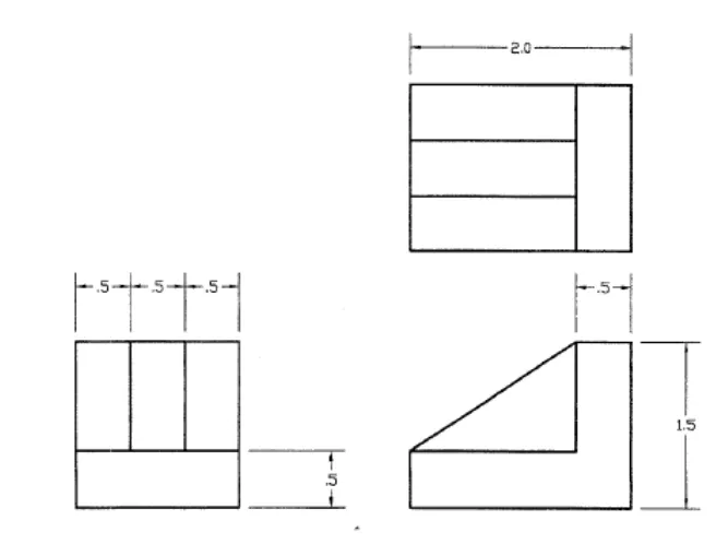
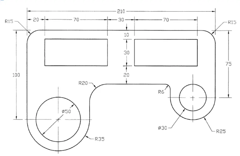
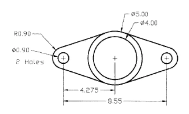
Figure - 5 Figure - 6 Figure - 7 Figure - 8
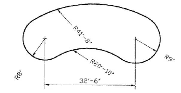
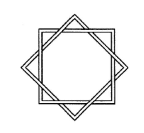
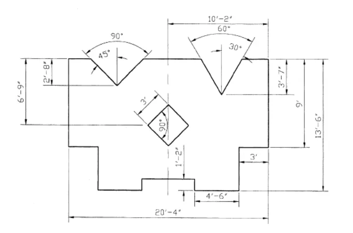
Figure - 9 Figure - 10 Figure - 11
FIGURE - 1:
AIM - To draw the given figure in detail using AutoCAD software.
Commands used -
- Line command
- Circle command
- Units command
- Dimstyle command
- Dimlinear command
- Dimangular command
- Dimalign command
PROCEDURE -
Step-1:
- In the command box type Units and select decimal unit
Step-2:
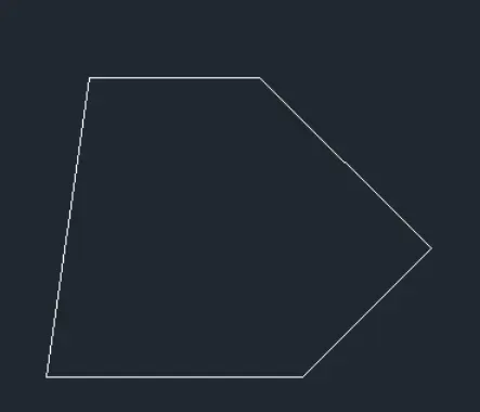
- In the command box type PL (Polyline).
- In the command box specify start point 1,1.
- In the command box type @3<0.
- In the command box type @2.12 <45.
- In the command box type @2.83<135.
- In the command box type @ 2<180.
- In the command box click close.
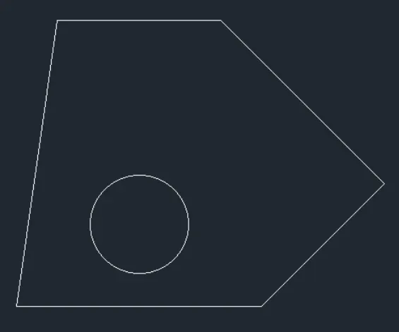
Step-3: To draw a circle.
- In the command box type OB (Object Snap).
- In the object snap click on ENDPOINT, MIDPOINT.
- Select the midpoint of line with dimension 3.
- In the command box type @1<90.
- In the menu bar click circle (centre, diameter).
- With the help of the cursor click on the endpoint of the previous line which is taken as centre of the circle.
- In the command box type 1.20 (diameter).
- Delete 1<90 line.
Step-4:
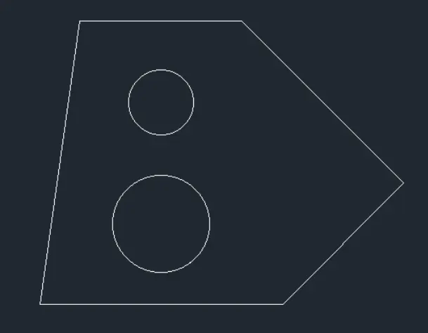
- In the command box type OB (Object Snap).
- In the object snap click on ENDPOINT, MIDPOINT.
- Select the midpoint of line with dimension 3.
- In the command box type @2.50<90.
- In the menu bar click circle (centre, diameter).
- With the help of the cursor click on the endpoint of the previous line which is taken as centre of the circle.
- In the command box type 0.80 (diameter).
- Delete @2.50<90 line.
RESULT -
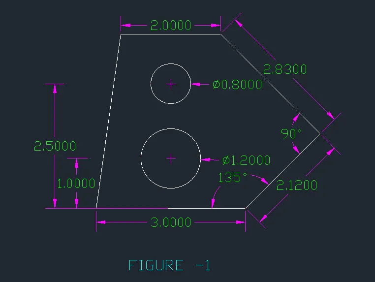
FIGURE - 2:
AIM - To draw the given figure in detail using AutoCAD software.
Commands used -
- Line command
- Circle command
- Units command
- Dimstyle command
- Dimlinear command
- Dimangular command
- Dimalign command
PROCEDURE -
Step-1:
- In the command box type Units>type>Architectural>precesion>0'-0"
Step-2:
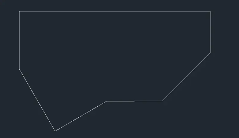
- In the command box type PL (Polyline).
- In the command box specify start point 2,5.
- In the command box type @2'10''<45.
- In the command box type @1'9''<90.
- In the command box type @8'<180.
- In the command box type @ 2'5''<270.
- Switch on Polar Tracking of 30,60,90.
- In the command box type @ 3'<60.
- In the command box type @ 2'6''<30.
- Then close the polygon with the starting point.
RESULT -
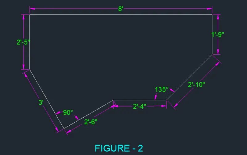
FIGURE - 3:
AIM - To draw the given figure in detail using AutoCAD software.
Commands used -
- Line command
- Circle command
- Units command
- Dimstyle command
- Dimlinear command
- Dimangular command
- Dimalign command
PROCEDURE -
Step-1:
- In the command box type Units>type>Engineering>precesion>0'-0"
Step-2:
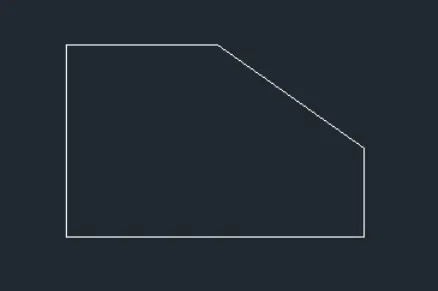
- In the command box type REC (Rectangle).
- In the command box specify start point 0,0.
- In the command box select dimension.
- In the command box type length 5'0.1''.
- In the command box type width 3'3''.
- In the command box type CHA (Chamfer).
- In the command box select dimension.
- In the command box type first chamfer distance 2'5.6''.
- In the command box type second chamfer distance 1'9''.
Step-3:
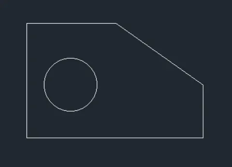
- In the command box type line.
- In the command box specify start point 0,0.
- In the command box type @1'3''<0.
- In the command box type @1'6''<90.
- In the menu bar click circle (centre, diameter).
- With the help of the cursor click on the endpoint of the previous line which is taken as centre of the circle.
- In the command box type 1'6'' (diameter).
- Delete @1'3''<0 and @1'6''<90 line.
RESULT -
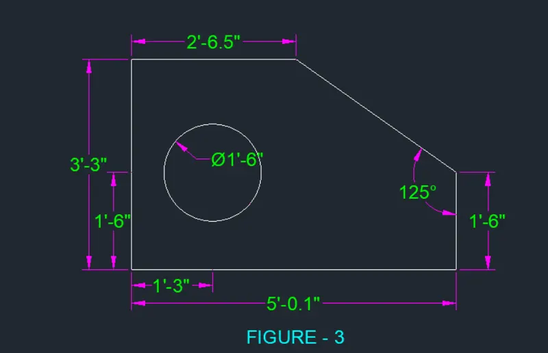
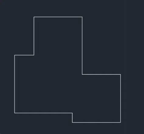
FIGURE - 4:
AIM - To draw the given figure in detail using AutoCAD software.
Commands used -
- Line command
- Circle command
- Units command
- Dimstyle command
- Dimlinear command
- Dimangular command
- Dimalign command
PROCEDURE -
Step-1:
- In the command box type Units>type>decimal>precesion>0.00
Step-2:
- In the command box type line.
- Specify a starting point 0,0.
- In the command box type distance 3.0<0.
- In the command box type distance 0.5<270.
- In the comman box type distance 2.5<0.
- In the command box type distance 2.5<90.
- In the command box type distance 2.0 <180.
- In the command box type distance 3.0<90.
- In the command box type distance 2.5<180.
- In the command box type distance 2.0<270.
- In the command box type distance 1.0<180.
- In the command box click close.
RESULT -
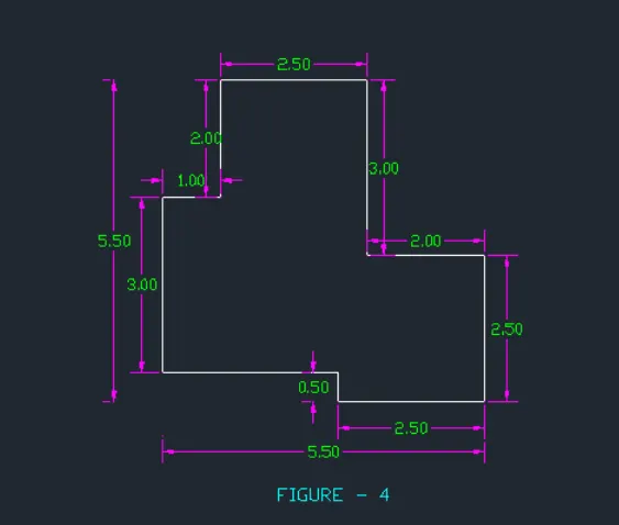
FIGURE - 5:
AIM - To draw the given figure in detail using AutoCAD software.
Commands used -
- Line command
- Circle command
- Units command
- Dimstyle command
- Dimlinear command
- Dimangular command
- Dimalign command
PROCEDURE -
Step-1:
- In the command box type Units>type>decimal>precesion>0.00
Step-2:
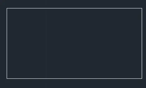
- In the command box type line
- In the command box type distance 11.5
- In the command box type distance 6.0
- In the command box type distance 11.5
- In the command box click close.
Step-3:
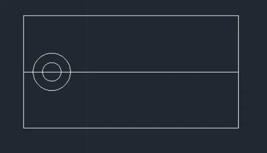
- Take a offset of 1.5 distance from 6 units line.
- Take a offset of 3.0 distance from 11.5 units line.
- The intersection point of the two lines as the centre of the circle
- In the menu bar click circle (centre, diameter).
- In the command box type 2.0 (diameter).
- Again in the menu bar click circle (centre, diameter).
- In the command box type 1.0' (diameter).
- Delete the line which is at the offset distance of 1.5
Step-4:
- Take a offset of 1.5 distance from 6 units line.
- The intersection point of the two lines as the centre of the circle
- In the menu bar click circle (centre, diameter).
- In the command box type 2.0 (diameter).
- Again in the menu bar click circle (centre, diameter).
- In the command box type 1.0' (diameter).
- Delete the line which is at the offset distance of 1.5
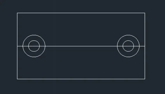
Step-5:
- Take a offset of 3.0 distance from both 6 unit lines.
- Again take a offset of 2.75 distance from previoius line from left side.
- The intersection point of the two lines previous offset line and horizontal line as the centre of the circle.
- In the menu bar click circle (centre, diameter).
- In the command box type 3.0 (diameter).
- Delete the line which is at the offset distance of 2.75 and 11.5 offset horizontal line.
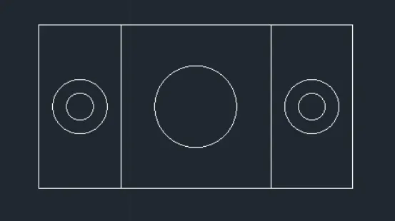
RESULT -
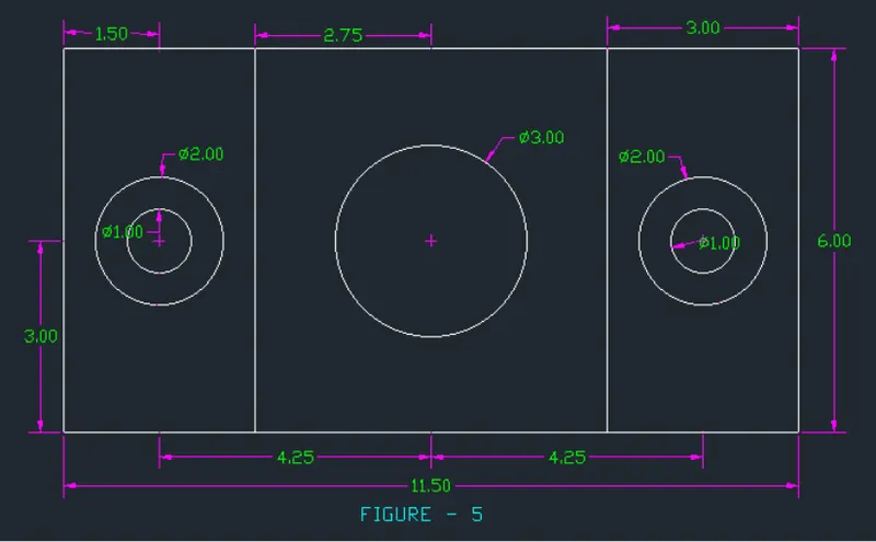
FIGURE - 6:
AIM - To draw the given figure in detail using AutoCAD software.
Commands used -
- Line command
- Circle command
- Units command
- Dimstyle command
- Dimlinear command
- Dimangular command
- Dimalign command
PROCEDURE -
Step-1:
- In the command box type Units >type> decimal > precesion > 0.00
Step-2:
- In the command box type line
- In the command box type distance 1.5
- In the command box type distance 1.5
- In the command box type distance 1.5
- In the command box select close
- In the command box type offset
- In the command box type offset distance 0.5
- With the help of offset get a horizontal line of distance 0.5
- With the help of offset get two vertical line of each distance 0.5
- Then use trim option to remove excess lines.
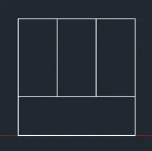
Step-3:
- In the command box type line
- In the command box type distance 2.0
- In the command box type distance 1.5
- In the command box type distance 2.0
- In the command box type distance 1.5
- In the command box type offset
- In the command box type offset distance 0.5
- With the help of offset get a vertical line of distance 0.5
- With the help of offset get two horizontal line of each distance 0.5
- Then use trim option to remove excess lines.
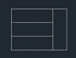
Step-4:
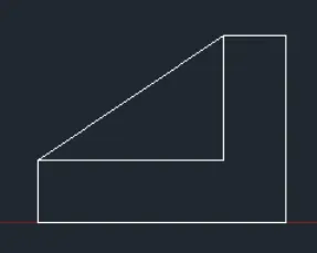
- Extended the horizontal lines from the right rectagular drawing.
- Extended the vertical lines from the top rectangular drawing.
- With the help of line command join the intersecton points.
- And trim the extras with the help of trim command.
RESULT -
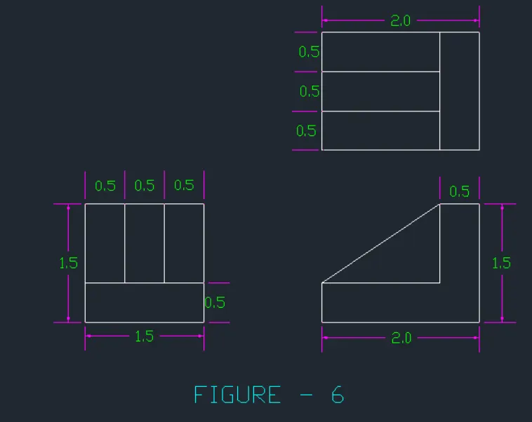
FIGURE - 7:
AIM - To draw the given figure in detail using AutoCAD software.
Commands used -
- Line command
- Circle command
- Units command
- Dimstyle command
- Dimlinear command
- Dimangular command
- Dimalign command
PROCEDURE -
Step-1:
- In the command box type Units>type>decimal>precesion>0.00
Step-2:
- In the command box type line
- In the command box type distance 100
- In the command box type distance 210
- In the command box type distance 75
- In the command box type fillet
- In the command box type radius > 15.0
- Select the 100 line and 210 line.
- Select the 210 line and 75 line.

Step-3:
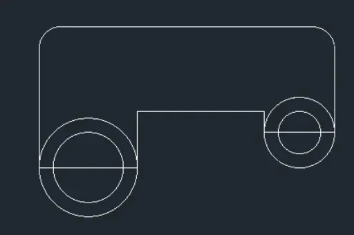
- From the end point of 100 draw a horizontal line of 70
- In the menu bar click circle (centre, diameter).
- Take the midpoint of the prevous line.
- In the command box type 50 (diameter).
- Again in the menu bar click circle (centre, diameter).
- In the command box type 70 (diameter).
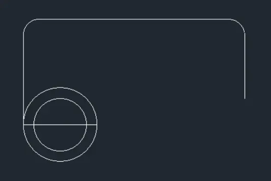
Step-4:
- From the end point of 75 draw a horizontal line of 50
- In the menu bar click circle (centre, diameter).
- Take the midpoint of the prevous line.
- In the command box type 30 (diameter).
- Again in the menu bar click circle (centre, diameter).
- In the command box type 50 (diameter).
- From the end point of line 50 draw a vertical line of 15 .
- Close the gap with the help of the line
Step-5:
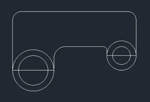
- In the command box type fillet > radius > 20
- Select the 40 line and 90 line from left side.
- In the command box type fillet > radius > 6
- Select the 15 line and 90 line from right side.
Step-6:
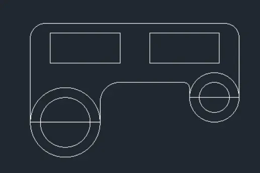
- In the command box type line
- Specify a starting point as a left top corner of figure.
- In the command box type distance @10<0
- In the command box type distance @20@270
- In the command box type REC (Rectangle).
- In the command box specify previous start point.
- In the command box select dimension.
- In the command box type length 70.
- In the command box type width 30.
- Again in the command box type line
- Specify the starting point as right bottom corner of rectangle.
- In the command box type distance @30<0
- In the command box type REC (Rectangle).
- In the command box specify previous start point.
- In the command box select dimension.
- In the command box type length 70.
- In the command box type width 30.
RESULT -
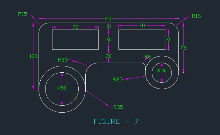
FIGURE - 8:
AIM - To draw the given figure in detail using AutoCAD software.
Commands used -
- Line command
- Circle command
- Units command
- Dimstyle command
- Dimlinear command
- Dimangular command
- Dimalign command
PROCEDURE -
Step-1:
- In the command box type Units>type>decimal>precesion>0.00
Step-2:
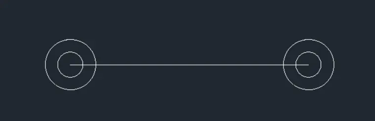
- In the command box type line
- In the command box type distance 2.0
- In the menu bar click circle (centre, diameter).
- Take the endpoint of the prevous line.
- In the command box type 0.9 (diameter).
- In the menu bar click circle (centre, diameter).
- Take the same point of the prevous line.
- In the command box type 1.8 (diameter).
- In the menu bar click circle (centre, diameter).
- Take another endpoint of the prevous line.
- In the command box type 0.9 (diameter).
- In the menu bar click circle (centre, diameter).
- Take the same point of the prevous line.
- In the command box type 1.8 (diameter).
Step-3:
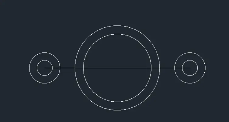
- In the menu bar click circle (centre, diameter).
- Take another midpoint of the prevous line.
- In the command box type 5.0 (diameter).
- In the menu bar click circle (centre, diameter).
- Take another midpoint of the prevous line.
- In the command box type 4.0 (diameter).
Step-4:
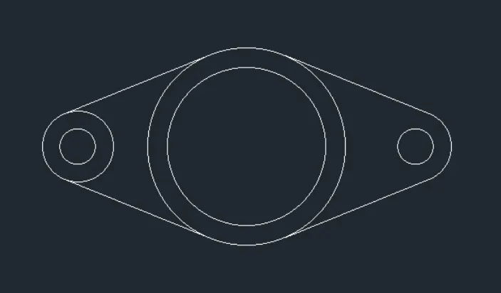
- Join the tangets of the outer circle with help of lines and trim the extras
RESULT -
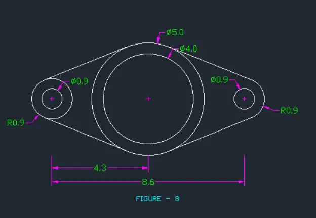
FIGURE - 9:
AIM - To draw the given figure in detail using AutoCAD software.
Commands used -
- Line command
- Circle command
- Units command
- Dimstyle command
- Dimlinear command
- Dimangular command
- Dimalign command
PROCEDURE -
Step-1:
- In the command box type Units>type>engineering>precesion>0'0.00''
Step-2:
- In the command box type line
- In the command box type distance 32'6''
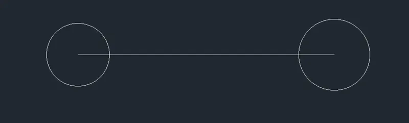
- In the menu bar click circle (centre, diameter).
- Take the left side endpoint of the prevous line.
- In the command box type 8' (diameter).
- In the menu bar click circle (centre, diameter).
- Take the right side endpoint of the prevous line.
- In the command box type 9' (diameter).
Step-3:
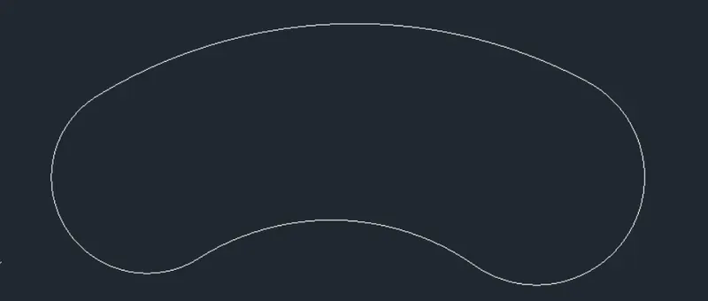
- In the command box type circle
- In the menu bar click circle (centre, radius).
- In the command box type draw the circle at the both sides of the line.
- In the command box type radius of left side is 33'-8" and right side is 32'*8"
- Now these two circle bisect at bottom
- In the command box type circle
- In the command box type select as center and radius
- In the command box type draw the circle at a point the bottom bisect of the circles.
- In the command box type radius of 41'-8"
- Now trim the unwanted lines.
- Now at the both of line.
- In the command box type circle.
- In the command box type select as tangent,tangent and radius.
- select the two circles as tangent.
- In the command box type radius of 20'-10"
- Finally trim the curve
RESULT -
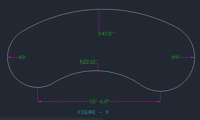
FIGURE - 10:
AIM - To draw the given figure in detail using AutoCAD software.
Commands used -
- Line command
- Circle command
- Units command
- Dimstyle command
- Dimlinear command
- Dimangular command
- Dimalign command
- Trim command
PROCEDURE -
Step-1:
- In the command box type Units>type>engineering>precesion>0'0.00''
Step-2:
- In the command box type REC (Rectangle).
- In the command box specify start point 0,0.
- In the command box select dimension.
- In the command box type size 5 x 5.
- In the command box type offset of some distance.
- After this trim the unwanted lines.
RESULT -
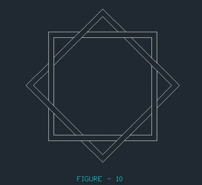
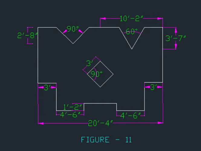
FIGURE - 11:
AIM - To draw the given figure in detail using AutoCAD software.
Commands used -
- Line command
- Circle command
- Units command
- Dimstyle command
- Dimlinear command
- Dimangular command
- Dimalign command
PROCEDURE -
Step-1:
- In the command box type Units>type>engineering>precesion>0'0.00''
Step-2:
- In the command box type line.
- In the command box specify start point 0,0.
- In the command box type @9'<270.
- In the command box type @3'<180.
- In the command box type @4'-6"<270.
- In the command box type @4'-6"<180.
- In the command box type @1'-2"<90.
- In the command box type @5'-4"<180.
- In the command box type @1'-2"<270.
- In the command box type @4'-6"<180.
- In the command box type @4'-6"<90.
- In the command box type @3'<180.
- In the command box type @9'<90.
- In the command box type @20'4<0.
- Take offset distance of 3' from corner and 2' 8" from top with offset command.
- With the line command draw a V and polar coordinates must be 45 .90,135,180.
- Take offset distance of 3' from corner and 3' 7" from top with offset command.
- With the line command draw a V and polar coordinates must be 30,60,90,120.
- Take offset distance of 10'2" from corner and 6' 10" from top with offset command.
- Keeping the intersection point as centre draw a diamond with radius 3 and angle 90.
RESULT -
FINAL RESULTS -
|
|
|
|
|
|
|
|
|
|
|