Creating a Floor plan, Footing detail and Isometric view using AutoCad
AIM -
To create a floor plan, footing detail and isometric view using AutoCAD tools.
Following Drawings to be drawn -
- C.1 - Cross section of load bearing wall over spread footing.
- C.2 - Cross section of isolated footing
- C.3 - Line diagram of two bedroom building
- C.4 - Cross section of a load bearing wall showing foundation details
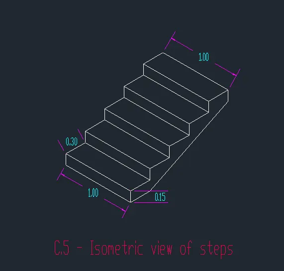
- C.5 - Isometric view of steps
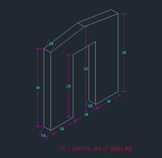
- C.6 - Isometric view of Gabble wall.
INTRODUCTION -
AutoCAD software consists of different tools that are essential for drawing a floor plan, footing detail or an isometric view. Some of them includes rectangle, polygon, polyline. There are various modification tools in AutoCAD which are used to modify the sketched objects and these includes move, copy, offsetting, rotating, scaling of sketched objects, filleting, chamfering etc.
- Rectangle - Command used is REC. It can also evoked from ribbon, toolbar, tool pallettes. Follow the commands in AutoCAD to complete the rectangle. Different ways by which rectangle can be drawn are:
- Drawing rectangle by specifying two opposite corners.
- Drawing rectangle by specifying area an one side length.
- Drawing rectangle by specifying their dimension.
- Drawing rectangle at an angle.
- Drawing using different options like chamfering, fillets, width, thickness, elevation.
- Regular polygon - Command used is POL. Other ways of evoking the tool is through ribbon, tool bar and tool pallettes. This tool is used to make a polygon with minimum of 3 sides and a maximum of 1024 sides. Different ways of drawing polygon is:
- Drawing a polygon by specifying the centre of the polygon:
- Drawing an inscribed polygon using centre of polygon option.
- Drawing a circumscribed polygon using the centre of polygon option.
- Drawing a polygon by specifying the edge.
- Drawing a polygon by specifying the centre of the polygon:
- Polyline - Command used is PLINE or PL and is also evoked through ribbon, toolbar, tool pallettes. There are two types of polyline: 2D and 3D. Different options in polyline includes arc, halfwidth, length and width. It is possible to switch between an arc and line anytime in between the drawing. Polyline is a very important tool in utility drawing like sewage lines, pipelines etc.
Modification Tools -
- Move -
- Command is MOVE, other ways of evoking is through ribbon, toolbar.
- There is a need to choose the base point about which the object is to be moved.
- Displacement option allows to simply move an object to any point we want
- Copy -
- Command used is CO or it can evoked from ribbon and toolbar.
- By using this tool an object can be copied to any distance that we choose, but when we copy an object without specifying the displacement distance it will be copied to apoint at a distance same as the distance of the original object from the origin.
- There are two options in copy. Single and multiple.
- Offset -
- Command used is O or OFFSET evoked from ribbon, toolbar.
- This tool enables to create the same object at a specific distance.
- Different options incude:
- THROUGH - In this option there is no need of providing offset distance. Offsetted image can be placed anywhere on drawing.
- ERASE - This option provides an option to erase the source object once offsetting is done.
- LAYER .
- Rotate -
- Command used is RO or it can be evoked from ribbon or toolbar.
- Different ways Include -
- Rotation of objects in different rotation angles( with the help of base point).
- Rotation of objects using reference option.
- Scale -
- Command used is SC or it can be evoked from ribbon or toolbar.
- This tool is used to reduce or increase the overall size of an object by a factor.
- Here, we have to provide a base point and then specify the scale factor.
- There is two option for scaling:
- COPY - Scale factor is to be provided, both source object and scaled object will be visible.
- REFERENCE - Only reference length is to be provided, scale factor will be automatically calculated.
- Fillet-
- Command used is FIL or is also evoked from ribbon and toolbar.
- This tool can be created through either radius option or using the select first object option.
- Different options available are polyline (all corner points will be curved), radius, trim(by choosing no trim option the straight line will be available along with the curved line), Multiple (filleeting can be done multile times).
- Chamfer -
- Command used is CHA or is also evoked from ribbbon and toolbar.
- Dieffernt options available are:
- Creating chamfer using distance option by just inputing the distance of the chamfer from the corner.
- Creating chamfer using the select first line option and first line is selected where we have to provide the first chamfered distance.
- Creating chamfer using polyline option.
- Creating chamfer using angle option one side length and angle measurement will be provided.
- Creating chamfer using trim option.
- Creating chamfer using method option.
- Creating chamfer using multiple option.
PROCEDURE -
C.1 - Cross section of load bearing wall over spread footing.
Steps -
- Open AutoCAD
- In the command box type QNEW
- click on imperical template , advaced setup , decimal
- In the command box type units
- Type - decimal, precision - 0.00 , angle - decimal degree
- In the command box type ds
- snap spacing (x and y spacing - 0.5 )
- grid spacing (x and y spacing - 0.5 )
- In the command box type REC (RECTANGLE)
- specify first corner point (1,1)
- In command box click dimensions
- specify length of the rectangle 0.90
- specify width of the rectangle 0.25
- In the command box type REC
- specify first corner point (1.2,1.25)
- In command box click dimensions
- specify length of the rectangle 0.50
- specify width of the rectangle 0.40
- In the command box type REC
- specify first corner point (1.25,1.65)
- In command box click dimensions
- specify length of the rectangle 0.40
- specify width of the rectangle 0.40
- In the command box type REC
- specify first corner point (1.30,2.05)
- In command box click dimensions
- specify length of the rectangle 0.30
- specify width of the rectangle 0.60
- In the command box type REC
- specify first corner point (1.30,2.65)
- In command box click dimensions
- specify length of the rectangle 0.30
- specify width of the rectangle 0.05
- In the command box type REC
- specify first corner point (1.30,2.7)
- In command box click dimensions
- specify length of the rectangle 0.30
- specify width of the rectangle 1.0
- In the command box type REC
- specify first corner point (1.25,2.05)
- In command box click dimensions
- specify length of the rectangle 1.15
- specify width of the rectangle 0.15
- In the command box type line
- specify starting point (0.40 ,2.05)
- In the command box type @0.15<90
- In the command box type @ 0.3<0
- In the command box type @0.15<90
- In the command box type @ 0.3<0
- In the command box type @0.15<90
- In the command box type @ 0.3<0
RESULT -
Cross section of load bearing wall over spread footing -
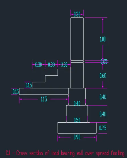
C.2 - Cross section of isolated footing
Steps -
- Open AutoCAD
- In the command box type QNEW
- click on imperical template , advanced setup , decimal
- In the command box type units
- Type - decimal, precision - 0.00 , angle - decimal degree
- In the command box type ds
- snap spacing (x and y spacing - 0.5 )
- grid spacing (x and y spacing - 0.5 )
- In the command box type line
- In the command promt specify start point (1,1.5)
- In the command box type @0.15<270
- In the command box type @1<0
- In the command box type @0.15<90
- In the command box type line
- In the command box type (1.04 ,1.09)
- In the command box type @0.05<90
- In the command box type @0.38<0
- In the command box type @1.96<90
- In the command box type @0.17<0
- In the command box type @1.96<270
- In the command box type @0.38<0
- In the command box type @0.05<90
- In the command box type line
- In the command box specify start point (1.42,3.00)
- In the command box type @0.04<180
- In the command box type @1.60<270
- Join coordinate points ( 1.38 ,1.40 ) and (1, 1.15 ) using line command
- In the command promtp specify start point (1.59,3.00)
- In the command box type @0.04<0
- In the command box type @1.60<270
- join coordinate points ( 1.63 ,1.40 ) and (2 ,1.15 ) using line command
- click on the line in which coordinate points are (1.42,3.00) and (1.59,3.00)
- In the command promt type offset
- In the command box type distance 0.20
- In the command box click multiple i.e click on the objects till we get the number of desired segments.
RESULT -
Cross section of isolated footing -
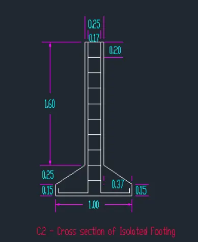
C.3 - Line diagram of two bedroom building
Steps -
- Open AutoCAD
- In the command box type QNEW
- click on imperical template , advaced setup , decimal
- In the command box type units
- Type - decimal, precision - 0.00 , angle - decimal degree
- In the command box type ds
- snap spacing (x and y spacing - 0.5 )
- grid spacing (x and y spacing - 0.5 )
- In the command box type line
- In the command box specify start point (1,1)
- In the command box type @3.60<0
- In the command box type @0.90<270
- In the command box type @1<0
- In the command box type @0.90<90
- In the command box type @4.20<0
- In the command box type @3.60<90
- In the command box type @4.20<180
- In the command box type @0.90<90
- In the command box type @1<180
- In the command box type @0.90<270
- In the command box type @3.60<180
- In the command box click close
- In the command box type line
- In the command box specify start point (4.60,1)
- In the command box type @0.90<90
- In the command box type line
- In the command box specify start point (4.60,4.60)
- In the command box type @1.80<270
- In the command box type offset
- In the command box type 0.30
- click on the line in which coordinate points are (4.60, 0.10) and (5.60,0.10)
- click on the previous line to get segments
- click on the line in which coordinate points are (4.60,5.50) and (5.60,5.50)
- click on the previous line to get segements
RESULT -
Line diagram of a two bedroom building -
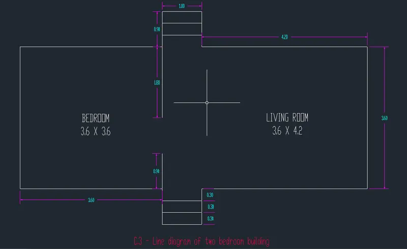
C.4 - Cross section of a load bearing wall showing foundation details -
Steps -
- Open AutoCAD
- In the command box type QNEW
- click on imperical template , advaced setup , decimal
- In the command box type units
- Type - decimal, precision - 0.00 , angle - decimal degree
- In the command box type ds
- snap spacing (x and y spacing - 0.5 )
- grid spacing (x and y spacing - 0.5 )
- In the command box type REC (RECTANGLE)
- Specify first corner point (1,1)
- In command box click dimensions
- specify length of the rectangle 0.90
- specify width of the rectangle 0.45
- In the command box type REC
- specify first corner point (1.15,1.45)
- In command box click dimensions
- specify length of the rectangle 0.60
- specify width of the rectangle 0.40
- In the command box type REC
- specify first corner point (1.20,1.85)
- In command box click dimensions
- specify length of the rectangle 0.50
- specify width of the rectangle 0.30
- In the command box type REC
- specify first corner point (1.25, 2.15)
- In command box click dimensions
- specify length of the rectangle 0.40
- specify width of the rectangle 0.60
- In the command box type REC
- specify first corner point (1.30, 2.75)
- In command box click dimensions
- specify length of the rectangle 0.30
- specify width of the rectangle 1.00
RESULT -
Cross section of load bearing wall showing foundation details -
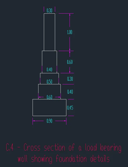
C.5 - Isometric view of steps -
Steps -
- Open AutoCAD
- In the command box type QNEW
- click on imperical template , advaced setup , decimal
- In the command box type units
- Type - decimal, precision - 0.00 , angle - decimal degree
- In the command box type ds
- In drafting settings (ds) make settings 'snap off' and 'grid off'.
- select on isometric snap
- keep ortho (f8) On
- In the command box type line
- Specify the point or select a point
- In the command box type unit distance 1.
- press f5 (isodraft) to get the line in desired direction
- In the command box type unit distance 0.15
- press f5 (isodraft) to get the line in desired direction
- In the command box type unit distance 0.30
- press f5 (isodraft) to get the line in desired direction
- This process is done till the steps are formed .
RESULT -
Isometric view of steps -
C.6 - Isometric view of Gabble wall -
Steps -
- Open AutoCAD
- In the command box type QNEW
- click on imperical template , advaced setup , decimal
- In the command box type units
- Type - decimal, precision - 0.00 , angle - decimal degree
- In the command box type ds
- In drafting settings (ds) make settings 'snap off' and 'grid off'.
- select on isometric snap
- keep ortho (f8) On
- In the command box type line
- Specify the point or select a point
- press f5 (isodraft) to get the line in desired direction
- In the command box type the required distance and mark the next points.
RESULT -
Isometric view of Gabble wall -
FINAL RESULT -
The given cross sectional drawings are drawn successfully in the detailed manner.