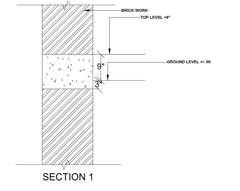
Creation of Column Schedule and Drawing Template using AutoCad
Ans.1.
AIM :-
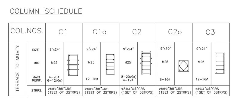
To create a column schedule with the help of lines and also insert text with the help of Dtext Command or Single line text.
INTRODUCTION :-
AutoCAD is a commercial computer-aided design (CAD) and drafting software application. It was developed and marketed by Autodesk. AutoCAD was first released in December 1982 as a desktop version.
PROCEDURE :-
1. Open the Autocad software and select any of the setup and enter values and finish the setup.
2.Now after that Select the line tool and draw a line by selecting a random point and draw a line of 100 units in x direction and 40 units in y direction and make a rectangle shaped figure with it.
3.After that select the offset tool by giving command of offset in the command bar and then give the offset distance as 8.33 units as we have given a line of 100 units in X direction and we have to make 12 lines in the table so for that 100 is divided by 12 to get the value of offset line. So offset of 8.33 units is given and 12 equal lines are made.
4. We can use the X line also to draw the horizontal line for the table.
5. After drawing the lines now use the trim tool to trim the external edges of the table.
6. Now use the text command which is available on the toolbar and selected on the single line text. Use required dimension of the text as 2 units and write the required text.
7. After writing all the text that are required you can also use the scale tool to scale the objects after writing if they are not in satisfactory size. For giving the diameter sign we have to use command %%C wherever required.
8. Now for drawing the columns that are given , draw a rectangle of dimension five units in X direction and 18 units in Y direction. And then copy the rectangle and place it in the other required boxes.
9. After that use the offset tool again to draw a rectangle in inner side of the bigger rectangle by giving the offset length as 0.5.
10. Here you can use the line tool to draw the lines as required in the figure and also you can use the spline tool to give the detailing of the steerups.
11. Now after the completion of the figure or the table we have to plot it. So go to the plot option that is available on the left top corner and after opening that use the printer or plotter option as per your desired requirement that is use JPG format or PDF format. Then select the paper size as A4. Plot area should be selected as window and then select the figure from the drawn area. And then preview it after pre-viewing use the plot option to plot it.
12. After plotting the designed figure or table you can also save it by going on the save option from the AutoCAD menu.
RESULT :-
Created column schedule is attached below :-
ANS 2.
AIM:-
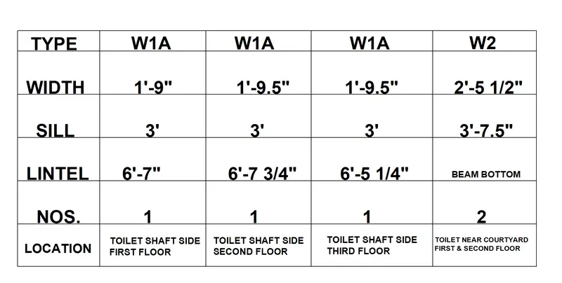
To create the given Window schedule with the help of Autocad software.
INTRODUCTION:-
AutoCAD is a commercial computer-aided design (CAD) and drafting software application. It was developed and marketed by Autodesk. AutoCAD was first released in December 1982 as a desktop version.
PROCEDURE :-
1. Open the Autocad software and select any of the setup and enter values and finish the setup.
2. Now select the rectangle tool and draw rectangle of length 100 units and width of 45 units. After creating that rectangle use the explore command from the command bar to explode the rectangle as the rectangle is a poly line that means it is a closed figure that's why we have to explode it to work upon it.
3. After the exploding has been done now use the offset command from the command bar and give the point as 20 units and then select the vertical line and draw offset lines.
4. After that use the X line command to draw the horizontal lines you can also use it to draw vertical lines but here I used X line to draw horizontal lines and draw 5 horizontal lines as per the required distance.
5. After drawing them Now use the trim tool to trim the extra lines and hence a table is being created. We can adjust the lines as per our requirement by using the grips of the lines and we can move them also as per our distance required.
6. Now use the text tool from the tool bar and select single line text and give a size of 2 units with font Arial and Bold style. And then write the required text in the boxes.
7. After writing the text you can also scale them as per the given figure and hence use the scale command to scale them.
8.Now after the completion of the figure or the table we have to plot it. So go to the plot option that is available on the left top corner and after opening that use the printer or plotter option as per your desired requirement that is use JPG format or PDF format. Then select the paper size as A4. Plot area should be selected as window and then select the figure from the drawn area. And then preview it after pre-viewing use the plot option to plot it.
9.After plotting the designed figure or table you can also save it by going on the save option from the AutoCAD menu.
RESULT :-
Created window schedule is attached below :-
ANS 3.
AIM:
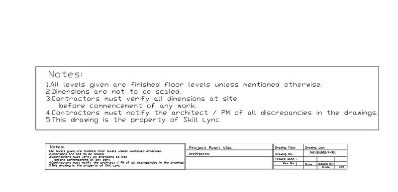
To create the drawing template using autocad software
INTRODUCTION:-
AutoCAD is a commercial computer-aided design (CAD) and drafting software application. It was developed and marketed by Autodesk. AutoCAD was first released in December 1982 as a desktop version.
PROCEDURE :-
1. Open the Autocad software and select any of the setup and enter values and finish the setup.
2.Then select the Text tool from tool bar and specify the size of text as 2 units and single line text should be selected.The font selected is txt.shx
3.After that write the given data in there and after completing that press enter to leave the command.
4.Now after writing all the text that are given in the figure it's time to draw the lines that are available in the figure for the drawing template.
5. To draw the lines select the rectangle tool from the toolbar and specify starting point for that and draw a rectangle around the text.
6. After drawing on rectangle now explode the rectangle using the explode tool from the toolbar and then extend the edges of the rectangle to a distance.
7. After extension of the line of the rectangle draw the required lines with the help of line tool or with the help of X line as per the given figure.
8. Then use the trim tool to trim the outer adjust that are not required for the template.
9. Write the text with the help of the text to again inside the boxes that are constructed with the help of the line tool or X line tool now.Font size is 2 units and font used is txt.shx
10.Now after the completion of the figure or the table we have to plot it. So go to the plot option that is available on the left top corner and after opening that use the printer or plotter option as per your desired requirement that is use JPG format or PDF format. Then select the paper size as A4. Plot area should be selected as window and then select the figure from the drawn area. And then preview it after pre-viewing use the plot option to plot it.
11..After plotting the designed figure or table you can also save it by going on the save option from the AutoCAD menu.
RESULT :-
Created drawing template is attached below :-
ANS.4.
AIM:-
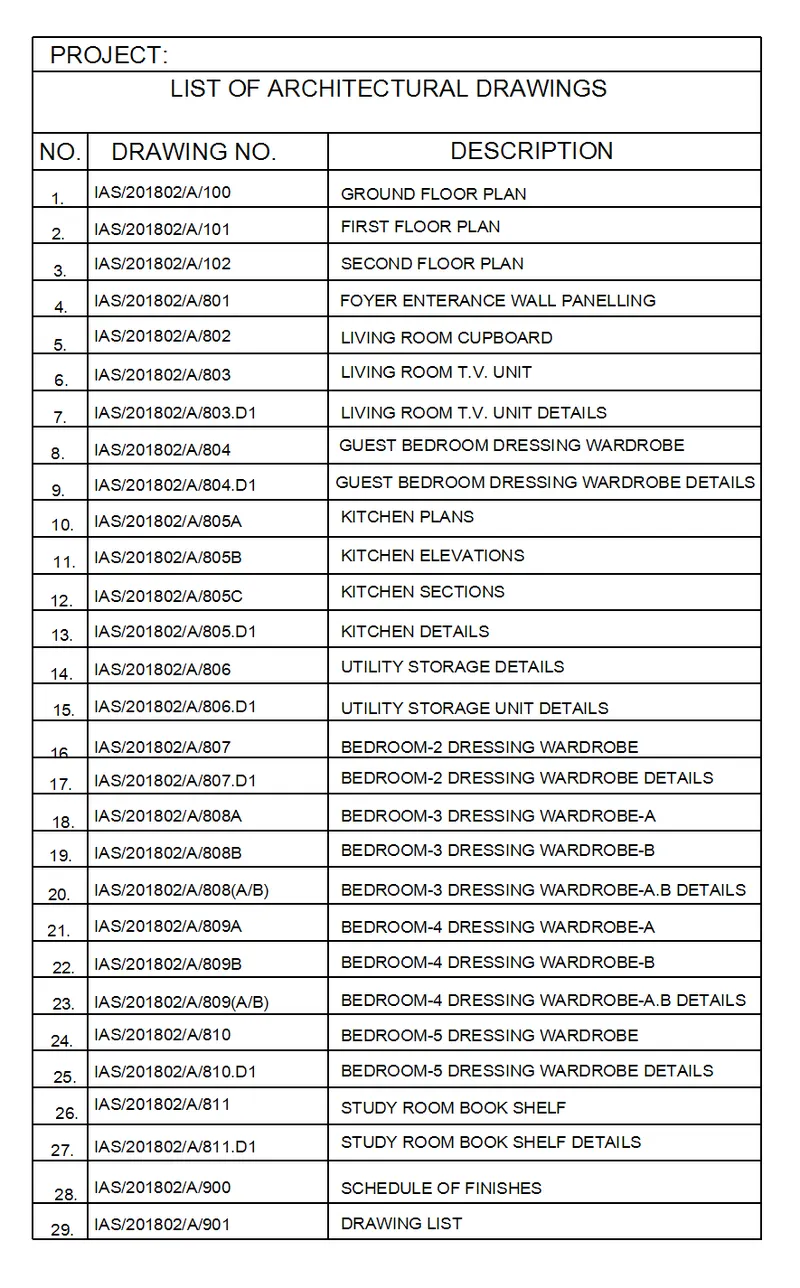
To create the drawing schedule as given using Autocad software.
INTRODUCTION:-
AutoCAD is a commercial computer-aided design (CAD) and drafting software application. It was developed and marketed by Autodesk. AutoCAD was first released in December 1982 as a desktop version.
PROCEDURE :-
1. Open the Autocad software and select any of the setup and enter values and finish the setup.
2. Select the rectangle tool to draw a rectangle of length 80 units and width 200units.
3. After that use the explode tool to explode the rectangle so that we can work upon it.
4. After exploding a rectangle now use the offset command from the command bar and give the offset distance as 26.67 and draw three offset lines. After drawing them adjust the first line as per the given figure.
5. Use the xline command to draw the horizontal line and draw required number of horizontal lines as per the given figure.
6. Use the trim tool to trim the external lines and the offset line and adjust the lines as per the given figure using the grips of the drawn line.
7. Now select the text tool from the toolbar with single line text and give the size as one unit and the text we are using is Arial. Write the required text as per the given figure.
8. After writing the text adjust the lines and text as per the requirements of the given figure using the grips. Use the scale option to scale the header and the description text in the table.
9.Now after the completion of the figure or the table we have to plot it. So go to the plot option that is available on the left top corner and after opening that use the printer or plotter option as per your desired requirement that is use JPG format or PDF format. Then select the paper size as A4. Plot area should be selected as window and then select the figure from the drawn area. And then preview it after pre-viewing use the plot option to plot it.
10.After plotting the designed figure or table you can also save it by going on the save option from the AutoCAD menu.
RESULT :-
Created drawing schedule is attached below.
ANS 5.
AIM:-
To create the beam detail as given using the Autocad software.
INTRODUCTION:-
AutoCAD is a commercial computer-aided design (CAD) and drafting software application. It was developed and marketed by Autodesk. AutoCAD was first released in December 1982 as a desktop version.
PROCEDURE :-
1. Open the Autocad software and select any of the setup and enter values and finish the setup.
2. Select the line tool and draw a line random co-ordinate of length 50 units in X direction and 150 units in Y direction and draw the line as given figure.
3. After that use the X line command to draw two horizontal lines As given in the figure. And then use the trim tool to trim the external lines.
4. After that use the break line command to give the break line in the edges of the column as shown in the given figure.
5. Specify the two points for the break line and then select the point where you want to give the break line and then select enter to show up the break line . Do the same for the other side also.
6. Now coming to the hatching,Select the upper and lower beam sections and type hatch command from the command bar and press enter after that the tool opens then select the settings option from that where you can select the type pattern colour of the hatching and use the pattern ANSI32 as it is used in the given figure for the upper and lower beam hatching. Then press preview to view the hatching.
7. If the hatching is not visible properly then you can always use the scale option from the setting menu of the hatching and enter the proper scale as required here I used the scale of 5units to hatch the figure.
8. Now for the concrete section again go to the hatch command by clicking the right click and going to the repeat hatch option then go to the settings again to select the concrete hatch.
9. Then select the type as predefined and go to the other pre-defined option and select the AR-CONC and enter the scale value as 3 and press enter to view.
10.Now coming to the dimensioning section, use the multi leader option from the annotate toolbar and type MLEADEREDIT first to specify the point for multileader.Use 3 point for multileader and then select a size for them.
11. After that use the multi leader where ever it is required in the figure and type the required text. Also you can edit the dimension by double clicking on the dimension and then write the given dimension as per your requirement or given figure.
12.Now after the completion of the figure or the table we have to plot it. So go to the plot option that is available on the left top corner and after opening that use the printer or plotter option as per your desired requirement that is use JPG format or PDF format. Then select the paper size as A4. Plot area should be selected as window and then select the figure from the drawn area. And then preview it after pre-wing use the plot option to plot it.
13.After plotting the designed figure or table you can also save it by going on the save option from the AutoCAD menu.
RESULT :-
Created Beam details in attached below :-