Creating a Residence Layout, Seating plan, Toilet and Utility room plan using AutoCad
AIM: Creating a Residence Layout, Seating plan, Toilet, and Utility room plan using AutoCad
INTRODUCTION: The following challenge is to check the skills of the student how accurately the student can use the layer properties and make the plan readable to the eyes. Here the commands like fillet, layer, layon, layoff, dimensions, trim, extend, hatch, rectangle, line, arcs, circle, join, explode, offsets, annotations, etc. are used. The drawings drawn are perfectly according to the units mentioned in the question. The dimensions which are not mentioned are assumed.
QUESTIONS:
Q1. Residence Plan:
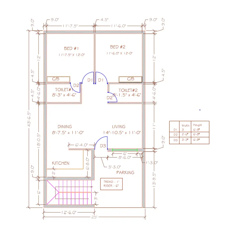
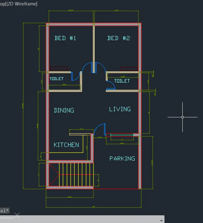
Sketch the layout of a residence as shown in Figure 1. Consider all dimensions as a reference to sketch the unit plan. Also, the text in the layout is only for reference. Assume the missing dimensions. Also, refer to the schedule for the size of the doors.
PROCEDURE:
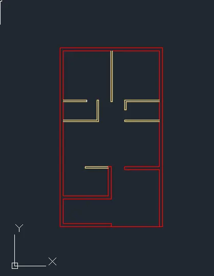
- Take the line command.
- Draw the layout plan of the floor given in the figure.
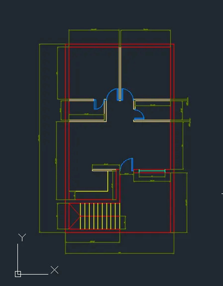
- The using Offset, trim, extend and fillet commands edit the plan, and reach the final plan.
- Now go to the layer properties section and add layers.
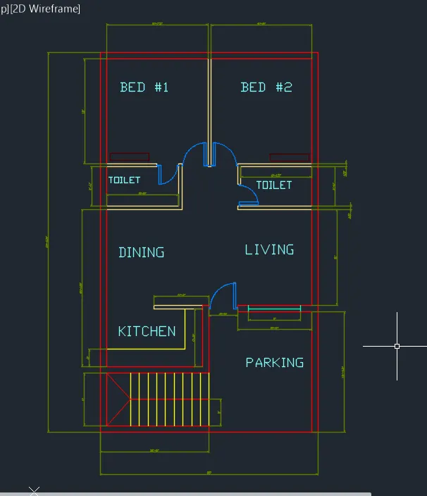
- Assign layers to each type of structure such as interior walls, exterior walls, labels, etc.
- Assign a different color to each layer.
- See the results in a very sophisticated way.
- Do the hatch to the walls.
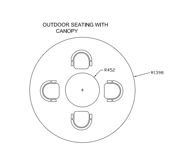
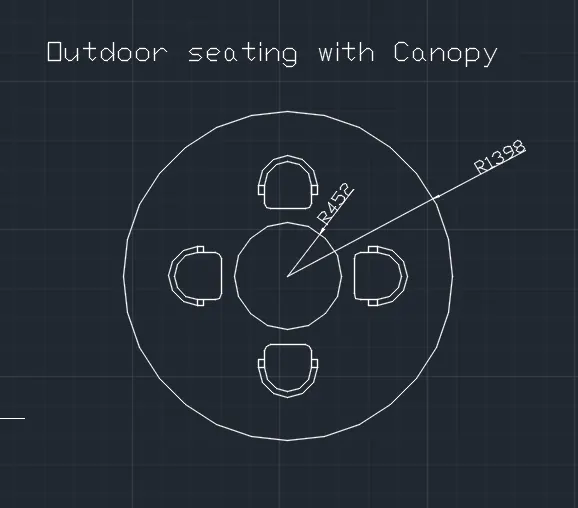
Q2. Sketch the seating plan for an outdoor canopy. Assume the dimensions for the seating. Also, consider the dimensions in mm.
PROCEDURE:
- Take the circle command.
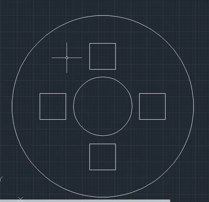
- Draw two concentric circles of radii 452 and 1398 units respectively.
- Now draw four squares of side length 400 units.
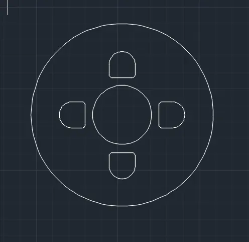
- Take fillet and give it the shape as shown in the figure.
- Use arcs to draw the handles of the chairs.
- Give dimensions of the table.
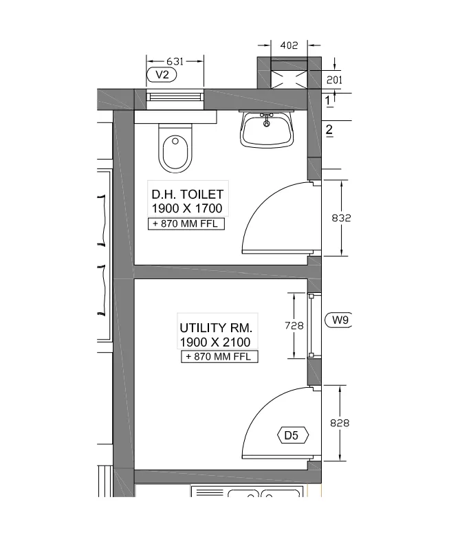
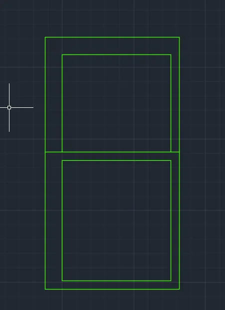
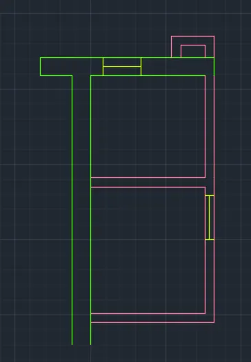
Q3. Sketch the part plan for the toilets and utility room. Consider the outer wall thickness as 300mm and inner wall thickness as 150mm. Also, assume the missing dimension, Texts, dimensions, and hatches are only for references. Also, symbols for toilets and w/c are also for references.
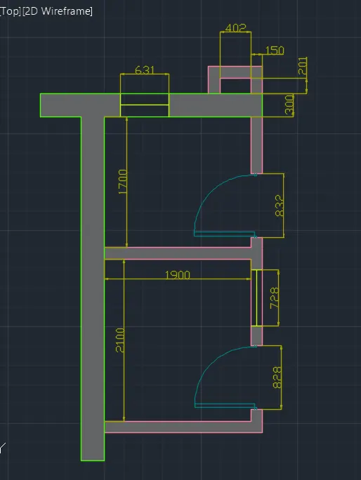
PROCEDURE:
- Take the line command.
- Draw the layout plan of the floor given in the figure.
- The using Offset, trim, extend and fillet commands edit the plan, and reach the final plan.
- Now go to the layer properties section and add layers.
- Assign layers to each type of structure such as interior walls, exterior walls, labels, etc.
- Assign a different color to each layer.
- See the results in a very sophisticated way.
- Do the hatch to the walls.
RESULTS: All the drawings are done using the best methods possible and the fastest way taught to draw a plan. The dwd file of the drawings attached above is attached in the attachments, please find the same below.