Drafting of various geometries using Chamfer, Fillet tool in AutoCad
Geometry #1
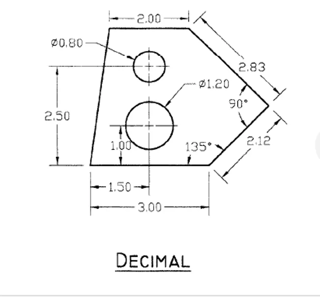
Aim: To draft the given geometry using AutoCAD with decimal units setting
Procedure:
- Create a New drawing file with Decimal as the units setting.
- Using the Limits command the limits are entered.
- Press the F8 key to switch the orthomode on
- Type L in the command box and select the line command. Draw a line of length 3 units in the +ve X direction.
- Turn the ortho mode off and Go to Object snap settings and under the polar tracking tab on the polar tracking and give the increment angle as 45.
- Now using the line command from the ribbon draw a line of length 2.12 units such that the inner angle is 135 degrees.
- Using the line command from the ribbon draw a line of length 2.83 units such that the inner angle is 90 degrees.
- Now switch on the ortho mode On again and using the line command draw a line of length of 2 units in the –ve X direction. Press the close command to finish the geometry.
- Press the F10 key on the Polar tracking. Select the circle command from the ribbon. Find the midpoint of the bottom line and using the reference line specify the first point at a distance as 1 from the bottom.
- Draw a circle of radius 0.6 units. And by the same method draw a circle of radius 0.4 units at a distance of 2.5 units from the bottom.
- Now using the Dimensions command mark the linear and angular dimensions of the geometry.
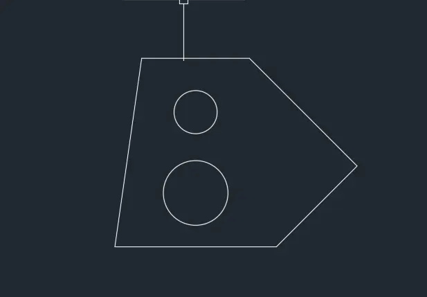
Result: The given geometry is drafted using AutoCAD.
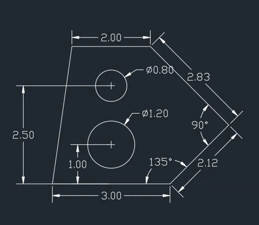
Geometry #2
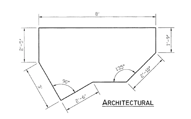
Aim: To create the given geometry using AutoCAD with architectural unit settings
Procedure:
- Create a New drawing file with Decimal as the units setting.
- Using the Limits command the limits are entered.
- Press the F8 key to switch the orthomode on
- Type L in the command box and select the line command. Draw a line of length 8’ units in the +ve X direction.
- Turn the ortho mode off and Go to Object snap settings and under the polar tracking tab on the polar tracking and give the increment angle as 45.
- Now using the line command from the ribbon draw a line of length 1’-9” units such that the inner angle is 135 degrees.
- Now using the line command from the ribbon draw a line of length 2’-10” units such that the inner angle is 135 degrees.
- Type L in the command box and select the line command. The left endpoint of the first line drawn is specified as the first point and a line of length 2’-5” units in the -ve Y direction.
- Using the polar tracking on and with an increment angle of 30, a line of length 3’ is drawn at an angle of 60 degrees.
- Using the polar tracking on and with an increment angle 30, a line of length 2’-6” is drawn at an angle of 30 degrees such that the inner angle of this line and the previous angel is 90 degree
- Now the gap between the two lines is closed using the line command.
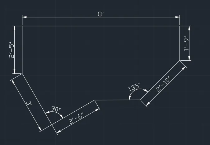
- The dimension command is used and all the linear and angular dimensions are marked.
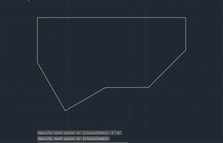
Result: The given geometry is drafted using AutoCAD
Geometry #3
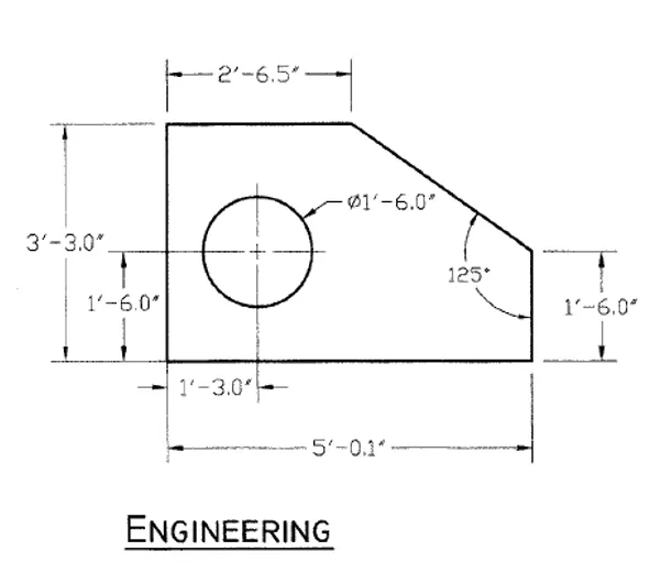
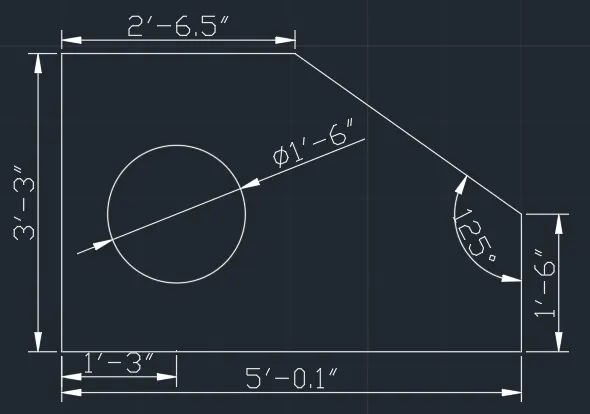
Aim: To create the given geometry using AutoCAD with Engineering unit settings.
Procedure:
- Create a New drawing file with Decimal as the units setting.
- Using the Limits command the limits are entered.
- Press the F8 key to switch the orthomode on.
- Type L in the command box and select the line command. Draw a line of length 5’-0.1” units in the +ve X direction.
- Select the line command. Draw a line of length 1’-6.0” units in the +ve Y direction.
- Type L in the command box and select the line command. The left endpoint of the first line is specified as the first point and a line of length 3’-3.0” is drawn units in the +ve Y direction.
- Type L in the command box and select the line command. Draw a line of length 2’-6.5” is drawn units in the +ve X direction.
- Now the gap between the lines to close the geometry is joined using line command and the inner angle is checked to be 135 degrees
- Using the Dynamic mode and the reference lines, a point at a distance of 1’-3.0” in the +ve X direction and a distance of 1’-6” in the +ve Y direction are marked.
- This point is used as a reference and a circle of diameter 1’-6.0” is drawn.
- The dimension command is used and all the linear and angular dimensions are marked
Result: The given geometry is drafted using AutoCAD
Geometry #4
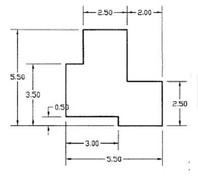
Aim: To create the given geometry using AutoCAD
Procedure:
- Create a New drawing file with Decimal as the units setting.
- Using the Limits command the limits are entered.
- Press the F8 key to switch the orthomode on
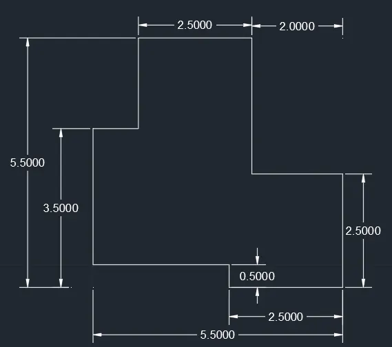
- Type L in the command box and select the line command. Draw a line of length 3 units in the +ve X direction.
- Type L in the command box and select the line command. Draw a line of length 3 units in the +ve Y direction from the first endpoint of the line.
- Type L in the command box and select the line command. Draw a line of length 0.5 units in the -ve Y direction from the last endpoint of the line.
- Type L in the command box and select the line command. Draw a line of length 2.50 units in the +ve X direction.
- Type L in the command box and select the line command. Draw a line of length 2.50 units in the +ve Y direction.
- Type L in the command box and select the line command. Draw a line of length 2 units in the -ve X direction.
- Type L in the command box and select the line command. Draw a line of length 3 units in the +ve Y direction.
- Type L in the command box and select the line command. Draw a line of length 2.50 units in the -ve X direction.
- Type L in the command box and select the line command. Draw a line of length 2 units in the -ve Y direction.
- Join both the end of the lines to close the geometry.
- The dimension command is used and all the linear dimensions are marked
Result: The given geometry is drafted using AutoCAD.
Geometry #5
Aim: To create the given geometry using AutoCAD
Procedure:
- Create a New drawing file with Decimal as the units setting.
- Using the Limits command the limits are entered.
- Press the F8 key to switch the orthomode on
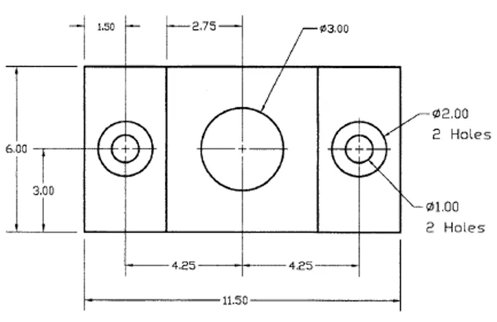
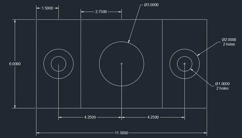
- Type L in the command box and select the line command. Draw a line of length 11.5 units in the +ve X direction.
- Type L in the command box and select the line command. Draw a line of length 6 units in the +ve Y direction.
- Type L in the command box and select the line command. Draw a line of length 11.5 units in the -ve X direction. Press Close.
- Offset both the vertical lines on both sides by a distance of 3 units.
- Turn on the dynamic mode, Select the circle command from the ribbon. Placing the cursor in the lower left corner enter the values as @1.5,3 and mark the center point of a circle of diameter 1 unit. Another circle of diameter 2 units is drawn using the same center point.
- Select the circle command from the ribbon. Similarly place the cursor in the lower right corner enter the values as @1.5,-3 and mark the center point of a circle of diameter 1 unit. Another circle of diameter 2 units is drawn using the same center point.
- Find the midpoint of the lower horizontal line and at a distance of 3 units in the +ve Y direction the center point of the circle is marked and a circle of diameter 3 units are drawn.
- The dimension command is used and all the linear and diameter dimensions are marked
Result: The given geometry is drafted using AutoCAD.
Geometry #6
Aim: To create the given geometry using AutoCAD
Procedure:
- Create a New drawing file with Decimal as the units setting.
- Using the Limits command the limits are entered.
- Press the F8 key to switch the orthomode on.
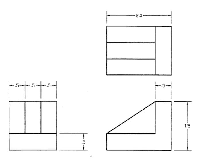
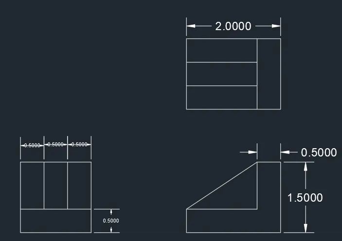
- Select Rectangle command and create a rectangle of dimensions 1.5*1
- Using the Line command and the copy tool a block of dimensions 1*0.5 is drawn three times.
- Using the polyline command from ribbon the lines are drawn in the following manner:
- 2 units at 0 degrees,
- 5 units at 90 degrees,
- 5 units at 180 degrees,
- 1 unit at 270 degrees,
- 5 unit at 180 degrees,
- And the close command is pressed.
- Two ends of the line are joined using the line command.
- Similarly at the top of the previously drawn geometry, Using the polyline command from ribbon the lines are drawn in the following manner:
- 5 units at 90 degrees,
- 5 units at 180 degrees,
- 5 units at 270 degrees,
- And the close command is pressed.
- Now again from the top left corner using polyline command
- 5 unit at 180 degrees,
- 5 unit at 270 degrees,
- 5 unit at 0 degrees,
- This object is copied using the copy command and the at the appropriate distance they are placed.
.
Result: The given geometry is drafted using AutoCAD.
Geometry #7
Aim: To create the given geometry using AutoCAD
Procedure:
- Create a New drawing file with Decimal as the units setting.
- Using the Limits command the limits are entered.
- Press the F8 key to switch the orthomode on.
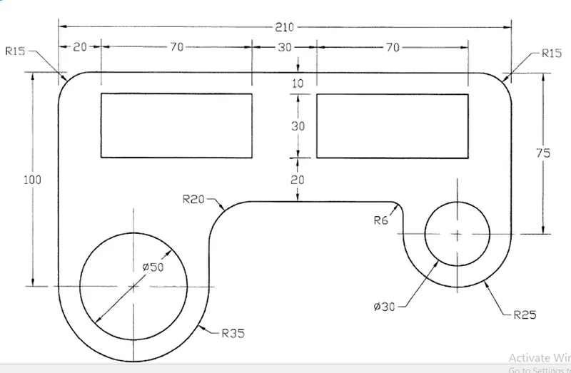
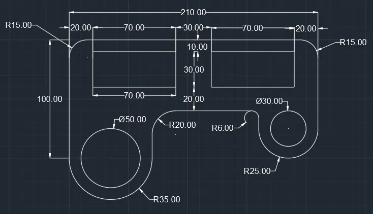
- Using the command Line from ribbon, 210 units horizontal line and 100 units vertical line on left side and 75 units vertical line on the right side are drawn. Since the arc has radius of 35, a line of 70 units is drawn on the left side and the arc has a radius of 25 a line of 50 units is drawn on the right side.
- Using the command Arc from ribbon and choosing the start, end, and radius an arc of radius 35 units on the right side and an arc of radius 25 units on the left side is drawn.
- Using the command Arc from ribbon, using the midpoint of 70m line on left side draw a circle of diameter of 50 units and 30 units on the right side.
- Using the offset command from ribbon, Offset the 210 units line at a distance of 60m down.
- Using the fillet command from ribbon, filleting is done for a radius of 15 units on the top right and left and a radius of 20 units on the inner left, and a radius of 6 units on the inner right.
- Using the fillet command from ribbon, offsetting is done for 210 units line to 10 Units and 100 units and 75 units line to 20 units.
- Using the rectangle command from ribbon, a rectangle of 70 units length and width of 30 units is drawn using the offset line.
- Using the erase command from the ribbon, the offset line and unwanted lines are erased.
- The dimension command is used and all the linear and diameter dimensions are marked
Result: The given geometry is drafted using AutoCAD.
Geometry #8
Aim: To create the given geometry using AutoCAD
Procedure:
- Create a New drawing file with Decimal as the units setting.
- Using the Limits command the limits are entered.
- Press the F8 key to switch the orthomode on.
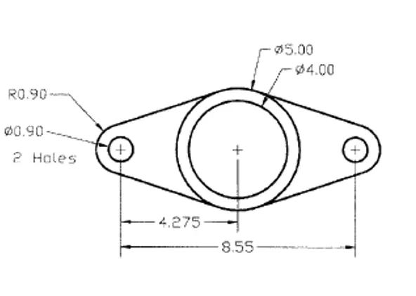
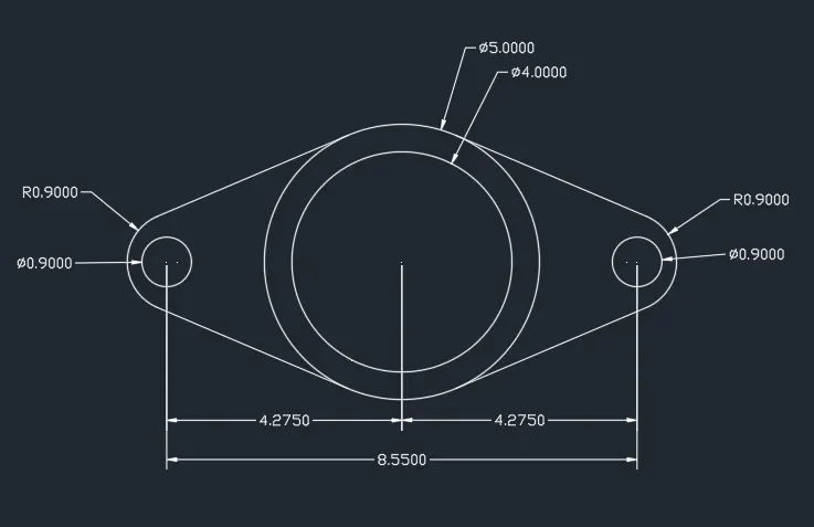
- Select the circle command from the ribbon, specify the center point as 50,50 and draw a circle of diameter 4 units
- Draw another circle of diameter 5 units from the same center point.
- Draw two circles of diameter 0.9 units at a distance of 4.275 units from the center point of the main circle on either side.
- Command Line: Select a point at a distance of 0.9 units above the center point of a small circle and specify it as the first point of the line. The second point is selected on the tangent point in the circle.
- The same procedure is done at a distance of 0.9 units below the center points. This procedure is carried on for the circle on the opposite end.
- Use the fillet command from the ribbon and give the radius as 0.9 units and close these two lines.
- The same procedure is carried out on the opposite end.
- The dimension command is used and all the linear and diameter dimensions are marked
Result: The given geometry is drafted using AutoCAD
Geometry #9
Aim: To create the given geometry using AutoCAD
Procedure:
- Create a New drawing file with Engineering as the units setting.
- Using the Limits command the limits are entered.
- Press the F8 key to switch the orthomode on.
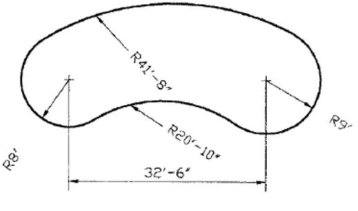
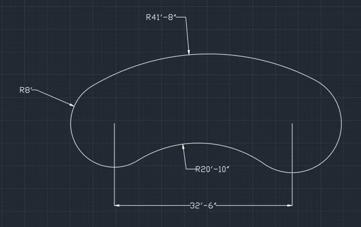
- Command Line: Draw a line of length 32’-06” units in the +ve X direction.
- Command circle: draw a circle of radius 8’ at one end and another circle of radius 9’ at another end.
- Use the fillet option to join both the circle at the bottom with a radius of 20’-10” units.
- The upper curve to join the circles is drawn by using two circles of radius 33’-8” and 32’-8” and another circle of radius 41’-8” is drawn to form the curve.
- All the unwanted lines are erased and trimmed.
- The dimension command is used and all the linear and diameter dimensions are marked
Result: The given geometry is drafted using AutoCAD
Geometry #10
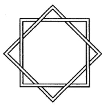
Aim: To create the given geometry using AutoCAD
Procedure:
- Create a New drawing file with Decimal as the units setting.
- Using the Limits command the limits are entered.
- Press the F8 key to switch the orthomode on.
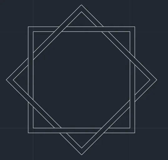
- Command Rectangle: Draw two rectangles, one bigger than the other with the same geometric center.
- Command rotate: copy and Rotate the drawn rectangles to a degree of 45.
- Trim all the unwanted lines.
Result: The given geometry is drafted using AutoCAD
Geometry #11
Aim: To create the given geometry using AutoCAD
Procedure:
- Create a New drawing file with Engineering as the units setting.
- Using the Limits command the limits are entered.
- Press the F8 key to switch the orthomode on.
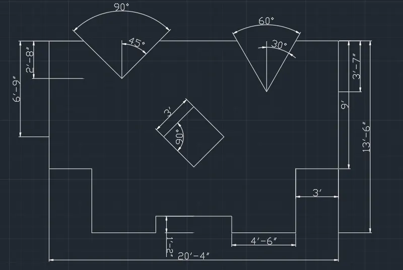
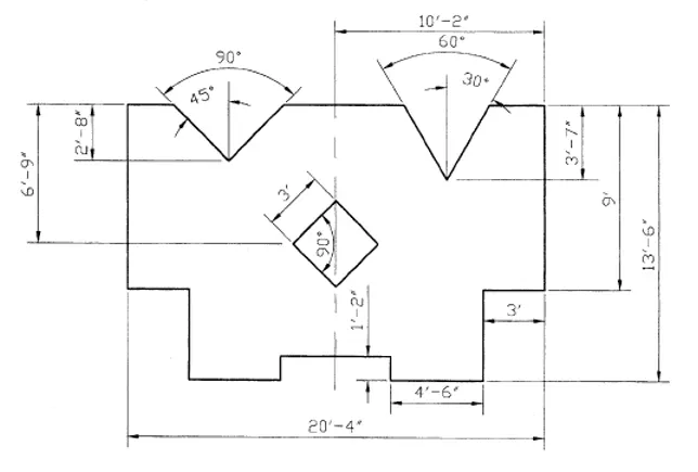
- Command-line: Draw 10’-2” horizontal line, 9’ vertical line, 3’ horizontal line 4'-6" vertical and horizontal line, and 1’-2" vertical line.
- Command mirror: Mirror the above lines at the center axis.
- Command offset: offset the 20’-4" to a distance of 6’-9” and 13'-6" to a distance of 10’-2".
- Command Rectangle: Draw a rectangle of length and width 3' from the center point of the offsetted line.
- Command Move: moving the center of the rectangle to the center of the offsetted line.
- Command rotate: Rotating the Rectangle by 45 degrees
- Command offset: Offsetting 20’-4" to a distance of 2’-8” with polar tracking on draw an angle of 90 degrees. Offset 20’-4” to a distance of 3’-7” with polar tracking on draw an angle of 60 degrees.
- Command erase: Erase the unwanted lines.
- The dimension command is used and all the linear and diameter dimensions are marked
Result: The given geometry is drafted using AutoCAD