Creating a Floor plan, Footing detail and Isometric view using AutoCad
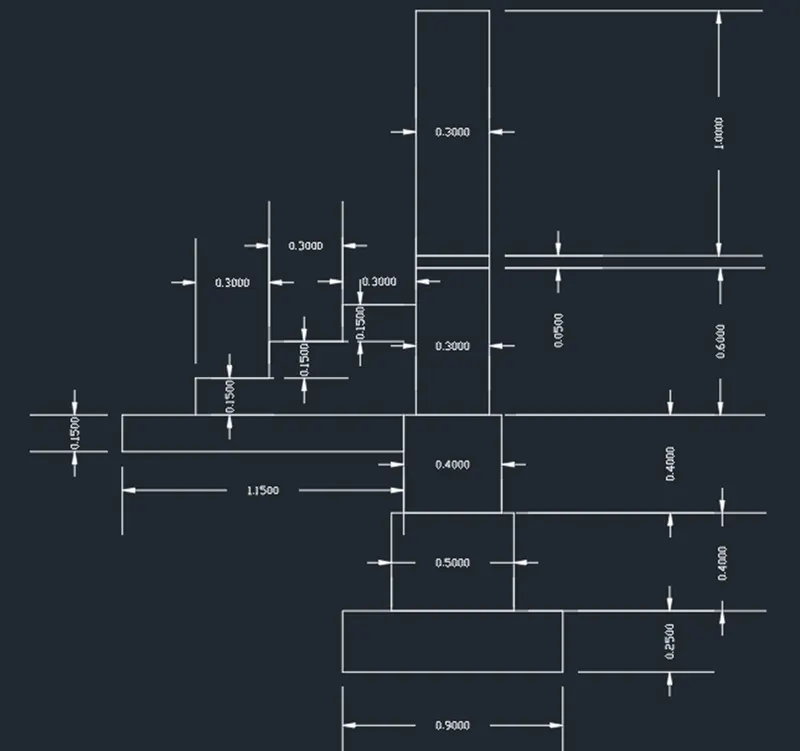
#1 C.S. Of Load Bearing Wall Over Spread Footing
Aim: To create the cross-section of the load-bearing wall over spread footing using AutoCAD.
Procedure:
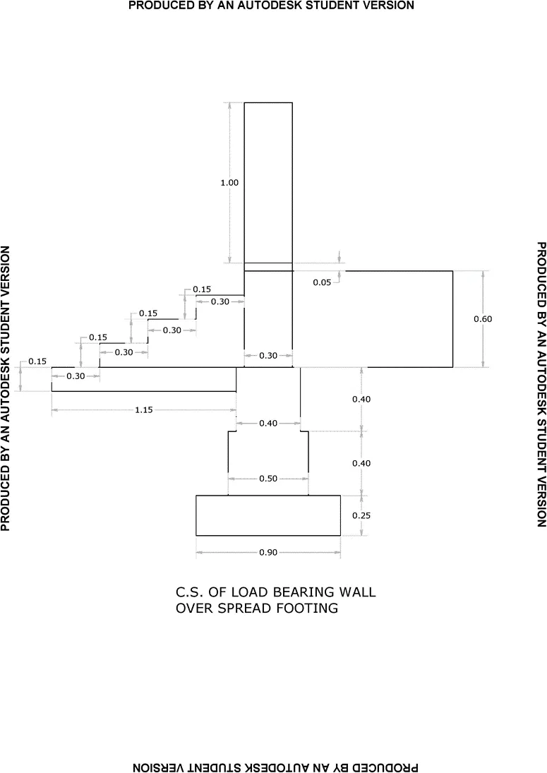
Step 1 :
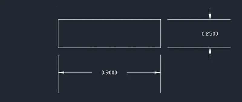
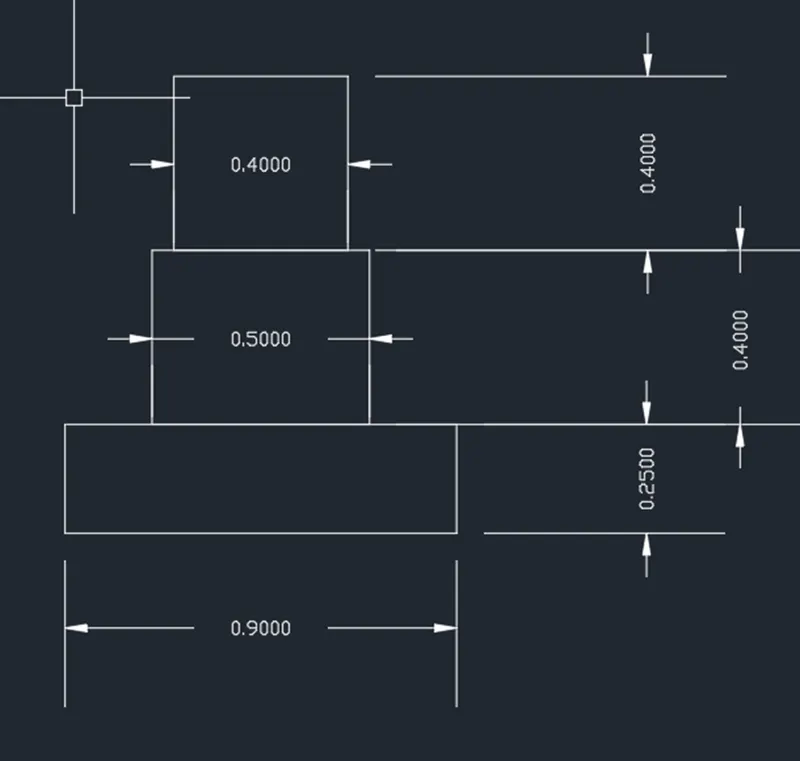
- Write ‘Rect’ in the command line and select the Rectangle tool
- Specify the first point as 6,6
- Select the dimensions and enter the length and breadth as 0.9 and 0.25 respectively
- Position the rectangle in the required way and click the cursor.
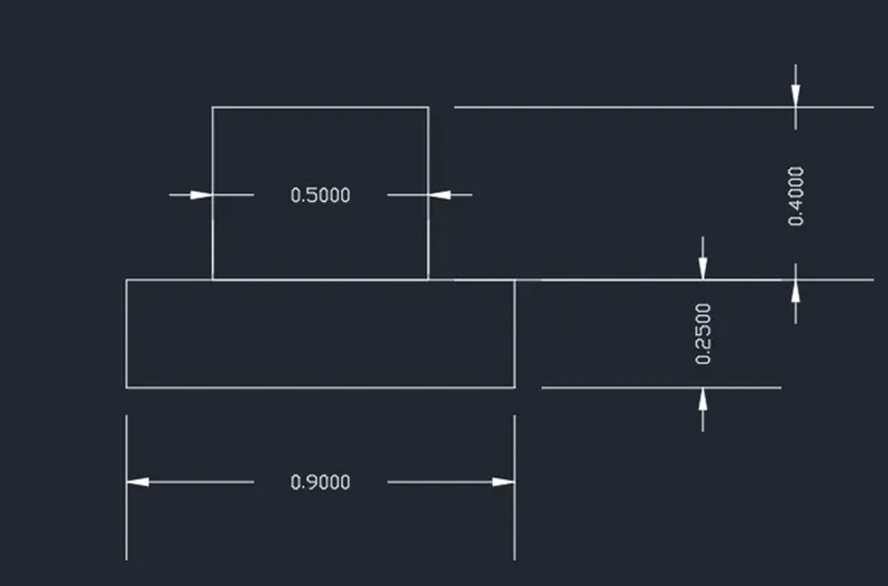
Step 2 :
- Select the rectangle tool from the command line and give the starting point 0.2 units away from the left corner of the rectangle.
- Enter the dimensions of the rectangle as length,0.5 and breadth 0.4 and press space
Step 3 :
- Select the rectangle tool from the command line and give the starting point 0.05 units away from the left corner of the rectangle.
- Enter the dimensions of the rectangle as length,0.4 and breadth 0.4, and press space
Step 4 :
- Select the rectangle tool from the command line
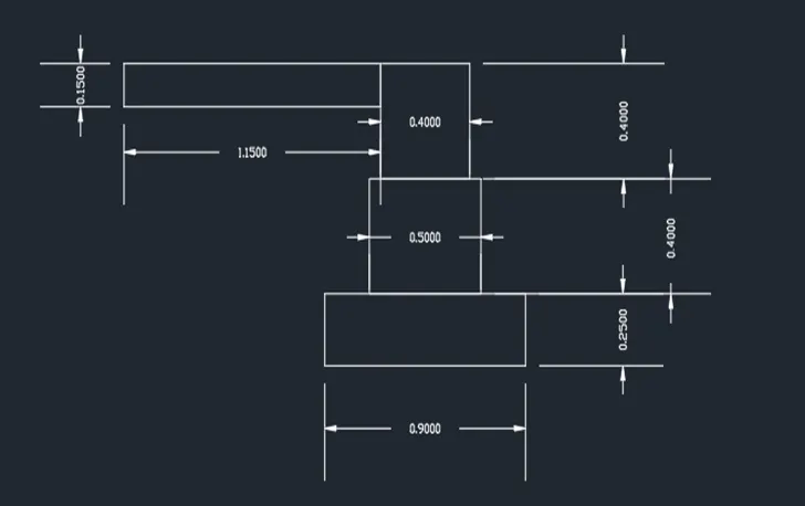
- Select the first point as the Top left corner point of the previous rectangle.
- Enter the value as @-1.15,-0.15, and press space.
Step5:
- Select the rectangle tool from the command line
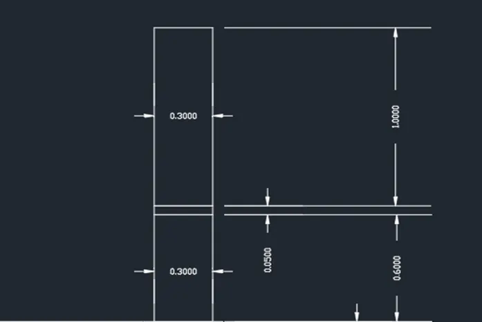
- Select the first point at a distance of 0.05 units from the top left corner point of the rectangle.
- Enter the value as @0.3,0.6 and press space.
Step 6:
- Select the rectangle tool from the command line
- Select the first point as the top left corner point of the previous rectangle.
- Enter the value as @0.3, 0.05, and press space.
Step 7:
- Select the rectangle tool from the command line
- Select the first point as the top left corner point of the previous rectangle.
- Enter the value as @0.3, 1.0, and press space.
Step 8:
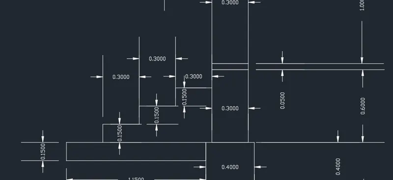
- Select the line tool from the command line by typing ‘LINE’
- Select the first point at a distance of 0.3 units from the left corner of the step footing.
- Click the orthomode on and by the Direct distance method enter the raise as 0.15 and the thread as 0.3
- Repeat the step two more times.
Result:
The cross-section of the load-bearing wall overspread footing is drawn using AutoCAD.
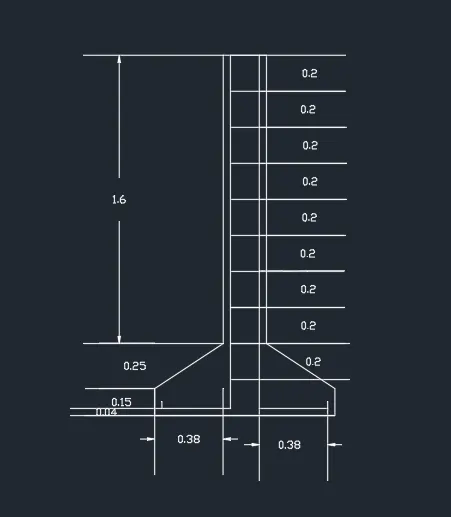
#2 C.S. Of Isolated Footing
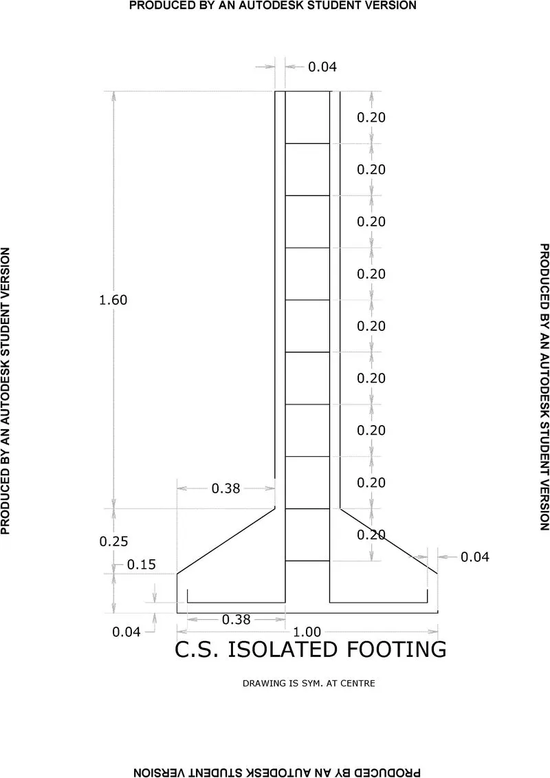
Aim: To create a cross-section of the given isolated footing using AutoCAD
Procedure:
Step 1:
- Select the Polyline command from the Command line by typing ‘POLY’
- Specify the first point as 4,4.
- Click the orthomode ON.
- By the rectangular coordinate system, Specify the value for the next point as @1,0.
- Specify the value for the next point as @0, 0.15
- Specify the value for next point as @-0.38, 0.25
- Specify the value for the next point as @0, 1.6
- Specify the value for next point as @-0.24, 0.
- Specify the value for the next point as @0,-1.6.
- Specify the value for the next point as @-0.38,-0.15.
- Select the close command from the command line.
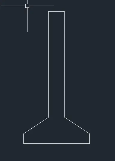
Step 2:
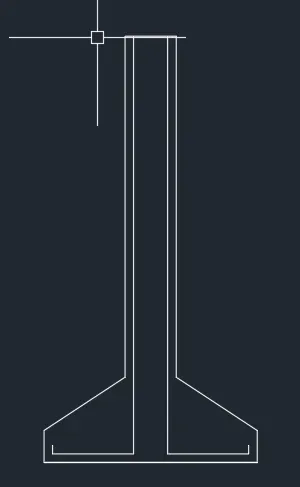
- Select the polyline command from the ribbon.
- Enter the first point as 10.04,10.08.
- Specify the value for the next point as @0, 0.04
- Specify the value for the next point as @0.38, 0.0.
- Connect the polyline to the top of the footing using the ortho mode command.
- Select the mirror command from the command line.
- Select the required objects using the cursor.
- The midpoint of the base of the footing is used as the first line of the mirror image.
Step 3 :
- Select the line command
- The dynamic Input is used to find the first point of the stirrup as 10.42,11.8
- A perpendicular line is drawn in the +ve x-axis.
- Using the copy tool the required object is selected.
- Using the left corner of the stirrup as a base point and the number of arrays is given as 8.
- The second point distance is given as @0.2<270.
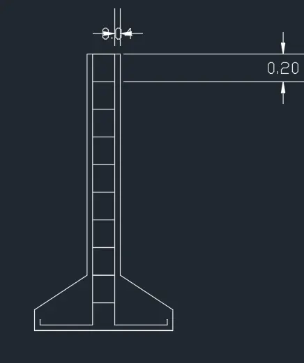
Result:
The given cross-section of the footing is drafted using AutoCAD.
#3 Line Diagram of a Two Bedroom Building
Aim: To draft the given line diagram of a two-bedroom building using AutoCAD
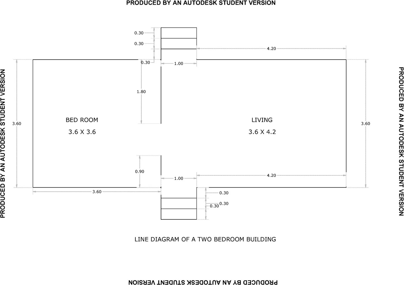
Procedure:
Step 1:
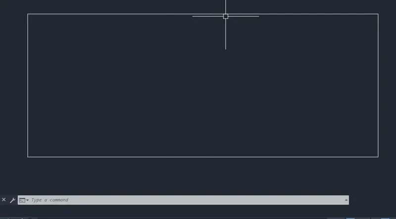
- Select the Polyline command from the command line
- Draw the plan layout using the given dimensions in such a way the steps and room have their own vertexes.
Step 2:
- Using the step vertex point in the plan layout
- The first thread of the step is drafted using the polyline command.
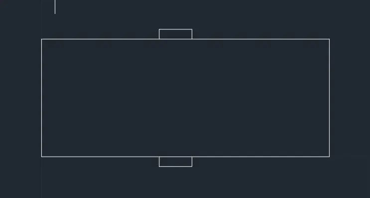
Step 3:
- The copy command is used and the copied object is moved at a distance of 0.3,0.6 respectively from the midpoint of the first step thread.
- The same procedure is carried out on the other side to draft the steps.
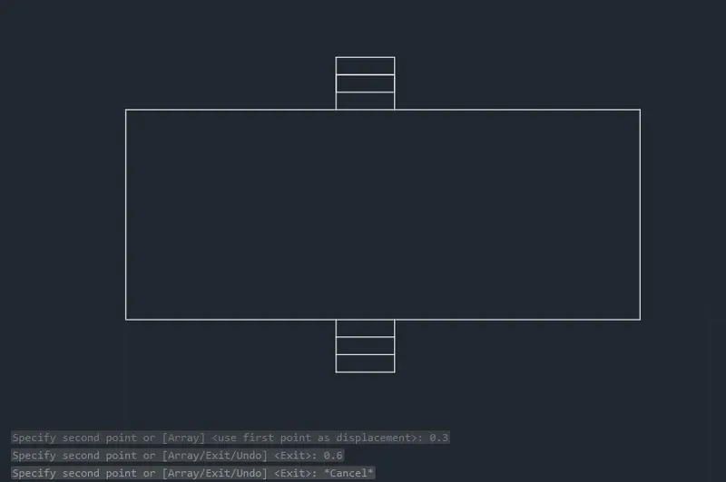
Step 4:
- The line along the plan layout Is removed
- By selecting the particular length of the line by holding the Ctrl key
- The delete key is pressed to erase it
- The same procedure is followed on the other side.
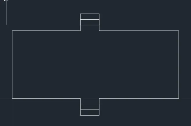
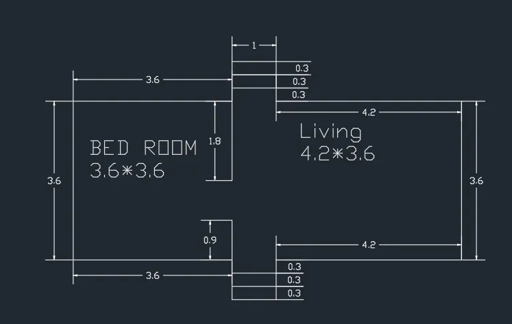
Step 5:
- The inner walls of length 1.8 units and 0.9 units are drawn.
- The dimension tool is used and all the dimensions of the layout are marked accurately.
Result: The given plan layout of the two-bedroom building is drawn using AutoCAD
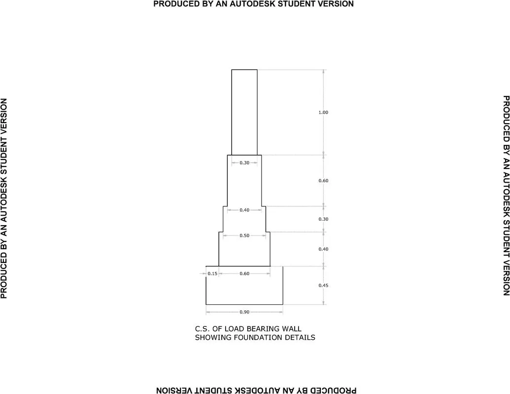
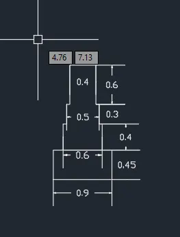
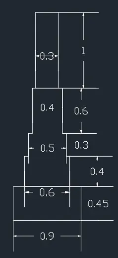
#4 CS of Load Bearing Walls Showing Foundation Details
Aim: To draft the given cross-section of load-bearing walls showing foundation details using AutoCAD.
Procedure:
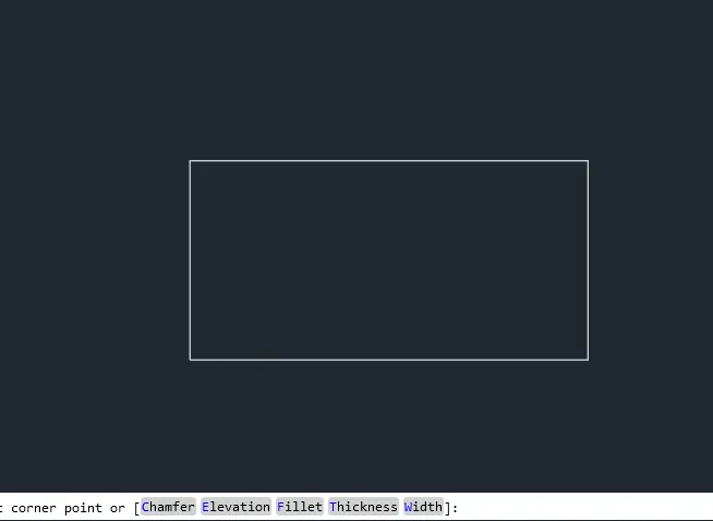
Step 1:
- Select the Rectangle command from the ribbon.
- Specify the first point as 5, 5.
- Select the dimensions option and enter the values as 0.9 and 0.45 for length and breadth respectively.
Step 2:
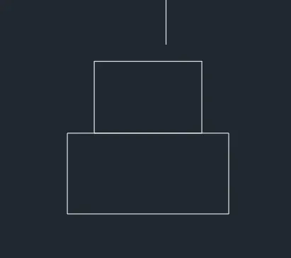
- Select the Rectangle command from the ribbon.
- Find the point at a distance of 0.15 from the left corner of the previous rectangle using the Dynamic mode.
- Specify it as the first point for the rectangle.
- Select the dimensions option and enter the values as 0.6 and 0.4 for length and breadth respectively.
Step 3:
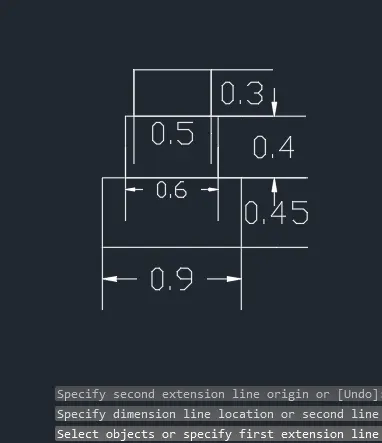
- Select the Rectangle command from the ribbon.
- Find the point at a distance of 0.05 from the left corner of the previous rectangle using the Dynamic mode.
- Specify it as the first point for the rectangle.
- Select the dimensions option and enter the values as 0.5 and 0.3 for length and breadth respectively.
Step 4:
- Select the Rectangle command from the ribbon.
- Find the point at a distance of 0.05 from the left corner of the previous rectangle using the Dynamic mode.
- Specify it as the first point for the rectangle.
- Select the dimensions option and enter the values as 0.4 and 0.6 for length and breadth respectively.
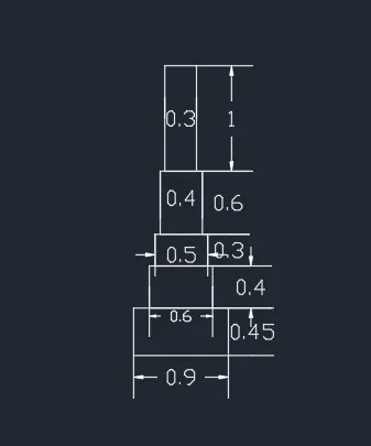
Step 5:
- Select the Rectangle command from the ribbon.
- Find the point at a distance of 0.05 from the left corner of the previous rectangle using the Dynamic mode.
- Specify it as the first point for the rectangle.
- Select the dimensions option and enter the values as 0.3 and 1.0 for length and breadth respectively.
- Trim the unwanted line using the Trim Command.
Result:
The given cross-section of the Load-bearing walls showing foundation details is drafted using AutoCAD
#5 Isometric View of Steps:
Aim: To create the isometric view of steps using AutoCAD
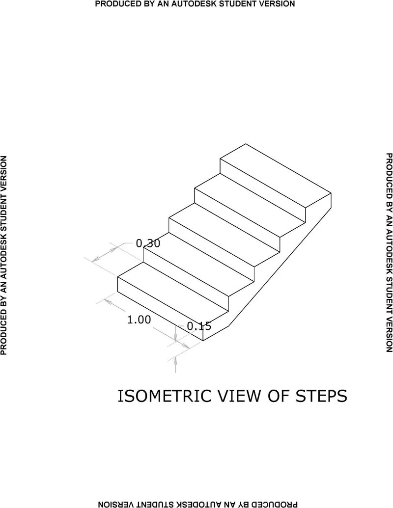
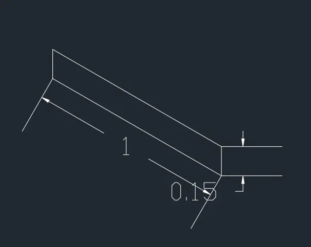
Step 1:
- From isometric drafting select iso-plane left.
- Give the command LINE and move the cursor to -X direction for 1 unit.
- Moving the cursor to the +Y direction, give 0.15 units. Moving the cursor to + x direction again for 1 unit and the cursor to -Y-direction gives 0.15 units.
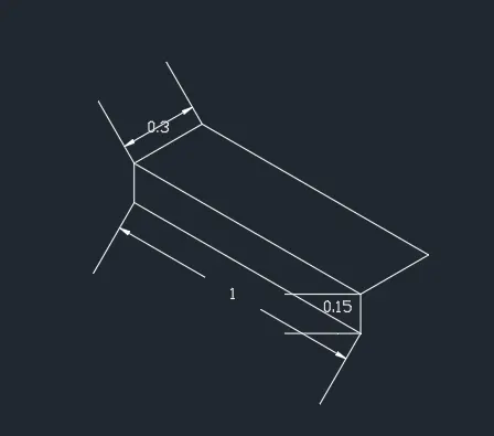
Step 2:
- Change the isometric drafting to iso-plane top
- Move the cursor to back and give 0.3 units from the last drawn point.
- Move the cursor in the right direction and give 1 unit. Move the cursor to the front for 0.3 units.
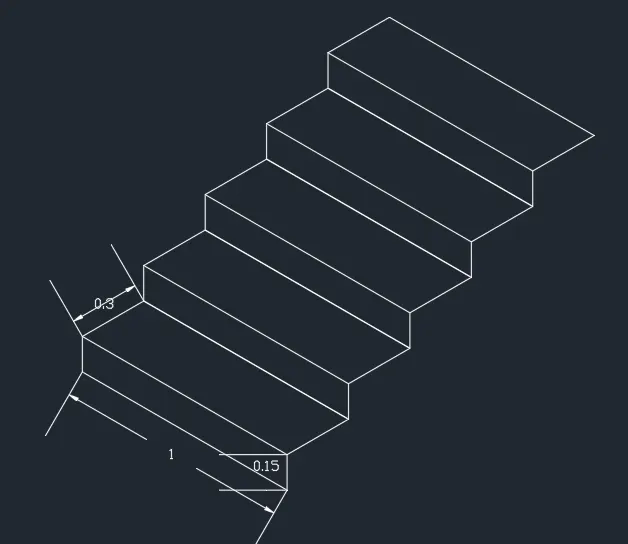
Step 3:
- Change the Isometric drafting to iso-plane right
- Copy the drawn object using the Copy command.
- Specify the base point of the object and position it accordingly.
- Repeat the process 4 times.
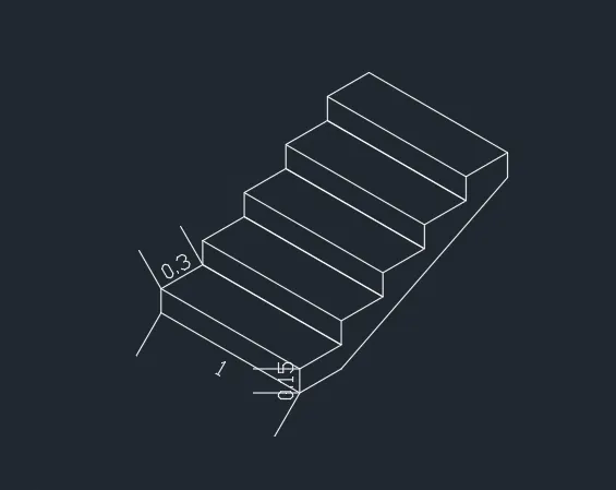
Step 4:
- Draw a line of length 0.3 units with the iso-plane top in the bottom
- Draw a line of length 0.15 units with the iso-plane right at the top.
- Join the two lines.
Result:
The given isometric view of stairs is drafted using the AutoCAD.
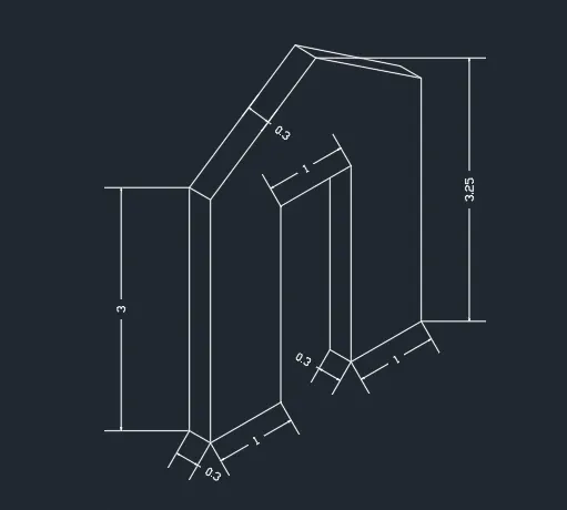
#6 Isometric View Of Gable Wall:
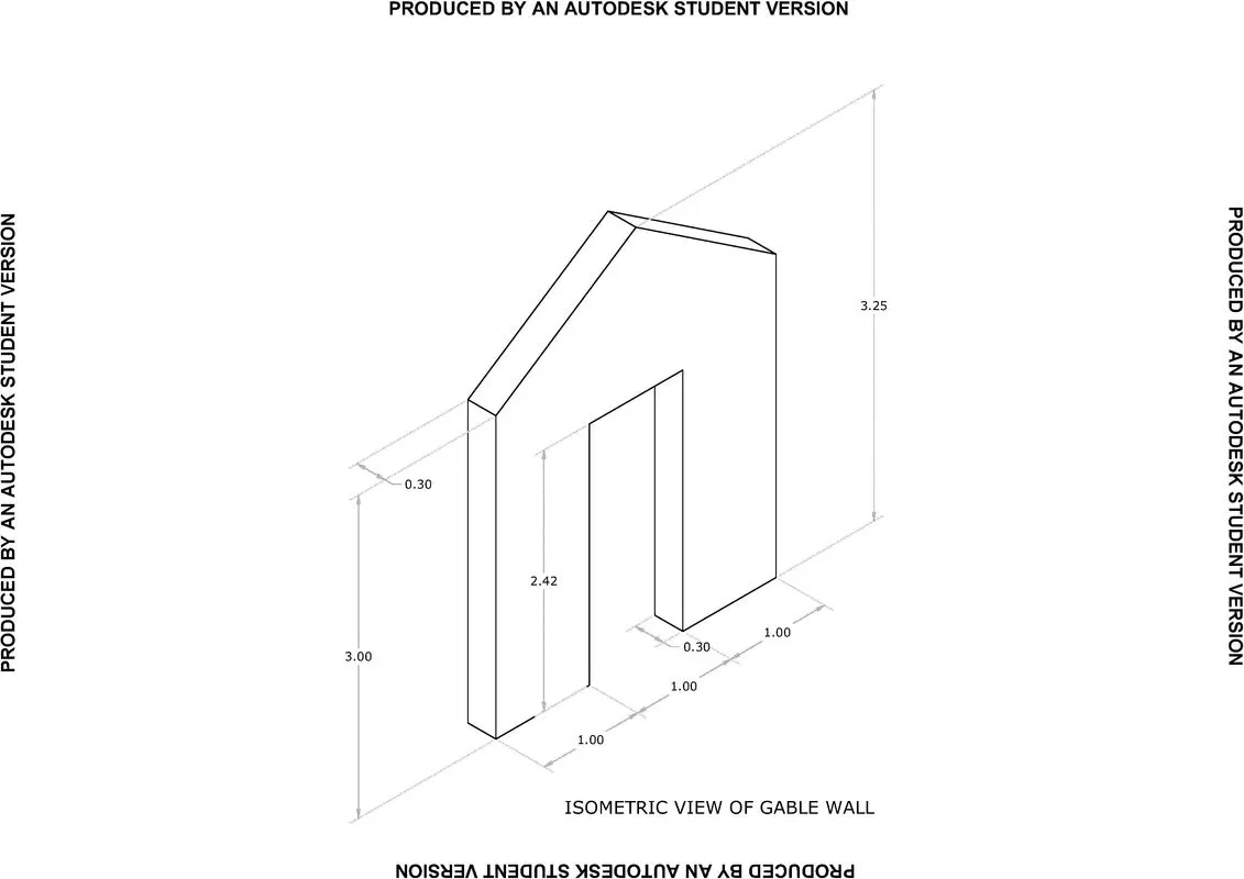
Aim: To create the isometric view of the Gable wall using AutoCAD
Step 1:
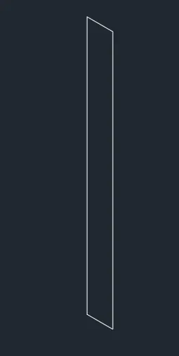
- The Isometric Drafting is changed to Isoplane left.
- Using the line command, a wall of thickness 0.3 unit and height of 1 unit is drawn.
Step 2:
- The Isometric Drafting is changed to Isoplane right.
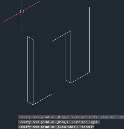
- Using the line command, The front face of the wall and the door is drawn in the right plane.
Step 3:
- The Isometric Drafting is changed to Isoplane right.
- A line of length 1.5 units is drawn horizontally with Ortho on
- A line of length 4 units is drawn upwards.
- The top end of the line and the wall are connected with the Ortho Off.
Step 4:
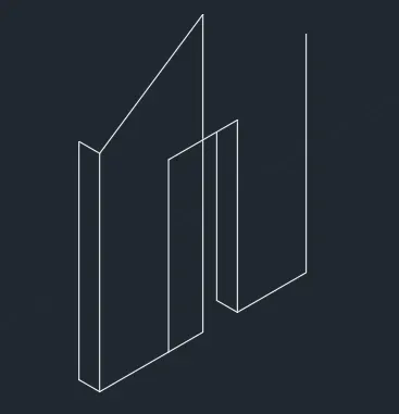
- Toggling between the Isoplane Left and Top the top face of the wall is drafted.
- The lines drawn for reference are erased using the Erase command.
- And the dimension command is used to mark the dimensions of all the wall sides.
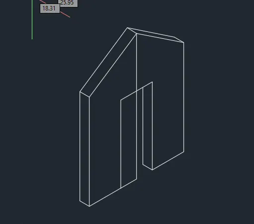
Result:
The isometric view of the Gable wall using AutoCAD is drawn.